

Moog Videolarm QODC4-50NA, QODC2-70NA, QODT2-50NA, QODT2-70NA, QODT2-70NA-X2 User Manual
...
81-IN5257-07024
QOD Q-View ObservaDome
QOD(T/C)X-XXXX
REVISION DATE: July 2, 2004
PRODUCT INSTRUCTIONS
TABLE OF CONTENTS
Cable and Power Guidelines 1, 10
Electrical Specifi cations 1
General Instructions 1
Wiring 1
Camera Adjustment 1
Camera Focusing 1
Camera Settings 2
Completion of Installation 4
NVT Instructions 4
Warranty Information 6
Service and Safeguard Information 7
Troubleshooting 8
CABLE AND POWER GUIDELINES (Detailed info on Page 10)
This chart shows the proper current needed for power supplies for
Q-View™ cameras. Use Class 2 Power only. Input voltage must
be 24 VAC/VDC.
CAMERAS VOLTAGE CURRENT POWER
1 24 VAC/VDC 102mA 2.5W
2 24 VAC/VDC 210mA 5W
3 24 VAC/VDC 331mA 7.9W
4 24 VAC/VDC 487mA 10.9W
Use the formula below to select the correct power supply for
cameras connected in parallel (positive to positive, negative to
negative):
4. Align the eyelet on the cord with the hole located on the inside of
the housing tile opening.
5. Insert the 6-32 x 1/2 round Phillips head screw through the
hole and eyelet. Place the star lockwasher and 6-32 hex nut on
the screw and tighten.
6. Fit the 2 x 2 housing tile in the desired location. The housing
tile will rest on the ceiling grid. (Be sure the grid is adequately
supported).
WIRING
1. Make the proper connections to the incoming power. The RED
wire is POSITIVE (+), the BLACK wre is NEGATIVE (-) (For refer-
ence purposes. Polarity is not important in this unit). The GREEN
wire, labeled Ground, is GROUND for VAC or VDC connections.
NOTE: Connect green ground wire to earth ground (metal conduit,
metal stud, etc.)
2. Attach the BNC connectors to the video in.
CAMERA ADJUSTMENTS
1. After completing installation of the housing, use the segmented
arms to adjust each camera to the desired viewing location.
2. Once camera adjustments are made, place the dome back into
position to be sure cameras are not touching the inside of the
dome. If any do, adjust until they are clear.
CAMERA FOCUSING
Total current for a 24 VAC system:
TOTAL CURRENT = (202mA x total number of cameras)
Note: 202mA is camera plus power supply
GENERAL INSTRUCTIONS
1. Remove contents from the box.
2. Remove the existing ceiling tile from the desired location.
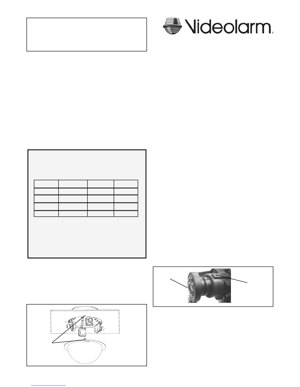
3. Insert the loose end of the saftey cord on the dome through the
middle hole on the edge of the housing opening (Figure 1).
Safety Cord
goes here
Figure 1
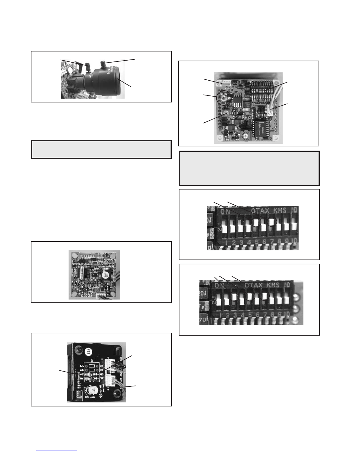
1. Fine focusing:
Fixed Lens: Loosen the set screw in the lens mount and
manually rotate the lens until a clear picture is achieved. Once
the focus is set, retighten the set screw (Figure 2).
Fixed lens
Set screw
Figure 2
- 1 -
Var i-Focal Lens: First, adjust the Magnifi cation Lock Screw to the
desired magnifi cation (telephoto to wide angle). Tighten the Lock
Screw. Next, adjust the Focus Lock Screw until a clear picture is
achieved. Tighten the Lock Screw (Figure 3).
Magnifi cation lock screw Focus lock screw
Fixed iris varifocal lens
Figure 3
Auto Iris Lens:
NOTE: THE AUTO IRIS LENS IS SET AT THE FACTORY.
• IF YOU EXPERIENCE VIDEO TOO LIGHT OR DARK
AUTO IRIS ADJUSTMENT MAY BE NEEDED.
SEE THE TROUBLESHOOTING SECTION FOR
ADJUSTMENT INFORMATION.
CAMERA SETTINGS
NOTE: To determine which camera is used in your unit, locate the
serial number on the inside of the housing. Match the two
letter prefi x with the corresponding instructions included
here for adjustments.
SERIAL NUMBERS BEGINNING WITH MC
The operational settings for the camera are defi ned by ten dip
switches located on the PC Board (Figure 6). Moving the switches to
the on position will activate each setting. Factory defaults are pictured
below (Figure 7 and 8).
Hi-Res Color, Fixed and Vari-focal fi xed lenses
Factory
Use Only
Auto Iris
adjustment
screw
DO NOT
ADJUST
Figure 6
NOTE: Dip switches are factory pre-set for optimum performance.
In certain specifi c instances it may be necessary to adjust
one or more settings. Consult a qualifi ed technician before
making any adjustments. A Dip Switch settings chart is
available on the next page.
FACTORY DEFAULT FIXED AND FIXED VARI-FOCAL LENSES:
Dip Switches 5 and 7 on, all others off.
Dip Switches
Connection to
Power Board
SERIAL NUMBERS BEGINNING WITH YK
FIXED AND FIXED VARI-FOCAL LENSES. There are no user
adjustable settings on these units (Figure 4).
BW Fixed and Vari-Focal
Figure 4
AUTO IRIS LENSES. The dip switches are factory set with AES
off and backlight compensation on (Figure 5). The auto iris is also
set at the factory, but an adjustment screw is included for use if
needed. See page 10 for instructions on adjusting Auto Iris.
BW Auto Iris
AES Default Off
Backlight
Compensation
Default On
Auto Iris
adjustment
screw
Figure 5
Figure 7
FACTORY DEFAULT AUTO IRIS LENSES:
Dip Switches 3, 5 and 7 on, all others off.
Figure 8
- 2 -
MC CAMERA DIP SWITCH SETTINGS CHART
SERIAL NUMBERS BEGINNING WITH CB
SWITCH SETTING DEFINITION
1 Setting this switch to "On" and
2
3
4
5
6
7
8
9
10
Flickerless Mode
switch 3 (MIRIS) to "Off" will
help to reduce the fl icker in
fl uorescent lights
BLC (Back Light
Compensation)
MIRIS (Manual/
Electronic Iris
GAMMA
AGCMAX
(auto/gain control)
(Automatic White
Balance Control)
AW1
AW2
AW3
AEREF
AEME
SHUTTER SPEED
Flickerless (1) BLC (2) MIRIS (3) Shutter Speed
On Off Off 1/100 Sec.
Off On Off 1/60 Sec.
Helps prevent an object from
being washed out when the
object is directly in front of a
light source.
When the switch is in the
on position the auto iris lens
controls the amount of light on
the chip. If in the off position
the light level is controlled
electronically.
Helps balance the contrast in
the picture.
Allows day/night cameras to
switch to b/w in low light conditions,
also helps with low light conditions
in standard and hi-res cameras
Used to help improve the
color quality of the camera
picture under different lighting conditions. The Factory Default is Switch 7 "ON",
switches 6 and 8 "OFF".
NOTE: ANY ADJUSTMENTS
TO THESE SETTINGS
SHOULD ONLY BE MADE
BY A QUALIFIED CCTV
TECHNICIAN
See examples below to help
with any adjustments.
This sets the electronic
convergence level. In the "off"
position the level is set to 100
IRE; in the "on" position the
user can set the level. Not
used with auto Iris
With this switch in the "On"
position users can manually
adjust the shutter speed and
gain using other switches See
the tables below for specifi c
settings
NOTE: This hi-res color camera uses a 1/4" chip and a 3-6mm
auto iris lens. It is comparable to a 1/3" chip using a
4-9mm auto iris lens.
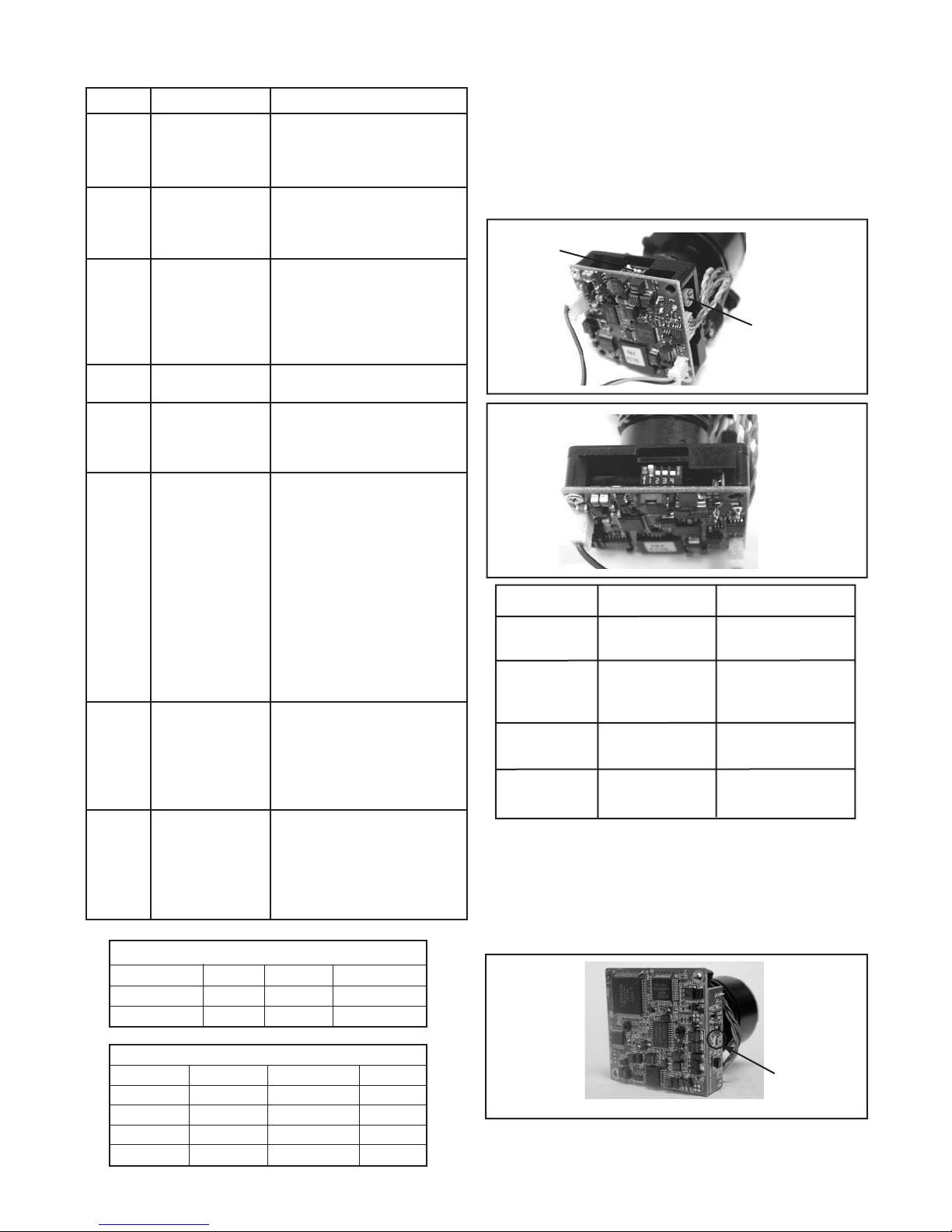
The operational settings are defi ned by four dip switches located on
the side of the PC Board (Figure 9 and 10). Moving the switches to
the UP position will activate specifi c settings. Refer to the chart below.
Dip Switches
Auto Iris
Adjustment
Screw
Figure 9
Figure 10
Dip Switch UP DOWN
1
(Iris) Auto Iris On Position for Fixed Lens
2
(Flickerless) Shutter speed Normal
fi xed at 1/100 sec.
3 (Back Light ON Normal
Compensation
4
(Synch Mode) Internal Synch Line Lock Mode
SERIAL NUMBERS BEGINNING WITH CT
FIXED AND FIXED VARI-FOCAL LENSES. There are no user adjustable settings on these units (Figure 11)
AUTO IRIS LENSES: The auto iris can be adjusted if needed. See the
Troubleshooting section for instructions.
GAIN
MIRIS (3) AEREF (9) AGCMAX (5) Gain
On Off Off 0dB
On On Off 6dB
On Off On 12dB
On On On 18dB
Auto Iris
adjustment
screw
Figure 11
 Loading...