

Moog Videolarm QMRT2-50NA, QMRT3-50NA, QMRT, QMRC Product Instructions
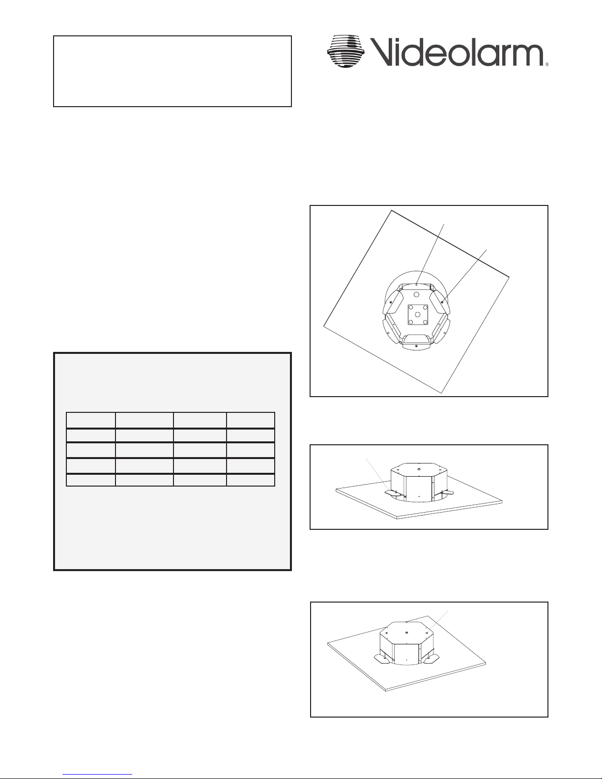
Mounting Holes
Support Arm Holes
Support Arms Rotate Out
Support Wires
81-IN5258-07064
QMR Ceiling Mount Dome
QMR(T/C)X-XXXX
REVISION DATE: July 6, 2004
TABLE OF CONTENTS
Cable and Power Guidelines 1, 11
Electrical Specifications 1
Housing Installation 1
Wiring 2
Camera Adjustment 2
Camera Focusing 2
Camera Settings
Black/White 2
Color 3
Completion of Installation 3
NVT Instructions 3
Exploded View 5
Warranty Information 6
Service and Safeguard Information 7
Troubleshooting 8
PRODUCT INSTRUCTIONS
4. Remove the trim ring/dome assembly by pulling on the outside
of the trim ring. The ring and dome are connected by three flat
springs, which press against the side of the housing and lock into
(3) cutouts.
5. Run electrical cable and video leads into the housing through the
conduit knock-out.
6. With the (3) support arms rotated to the inside, slide the housing
into the pre-cut hole (Figure 1).
CABLE AND POWER GUIDELINES (Detailed info on Page 11)
This chart shows the proper current needed for power supplies for
Q-View™ cameras. Use Class 2 Power only. Input voltage must
be 24 VAC/VDC.
CAMERAS VOLTAGE CURRENT POWER
1 24 VAC/VDC 102mA 2.5W
2 24 VAC/VDC 210mA 5W
3 24 VAC/VDC 331mA 7.9W
4 24 VAC/VDC 487mA 10.9W
Use the formula below to select the correct power supply for
cameras connected in parallel (positive to positive, negative to
negative):
Total current for a 24 VAC system:
TOTAL CURRENT = (202mA x total number of cameras)
Note: 202mA is camera plus power supply
HOUSING INSTALLATION
1. Carefully remove all equipment from the box.
2. Place the 11 1/8" template provided with the unit at the desired
location on the ceiling. Trace around the template, then cut a hole
in the ceiling following the trace lines.
3. Remove the desired conduit knock-out from the top of the QMR
housing.
Figure 1
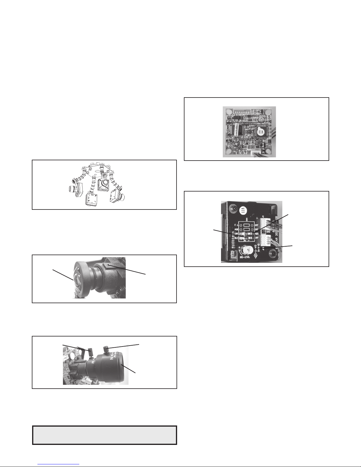
7. With the bottom flange pressed up against the ceiling, rotate the
support arms to the outside, the arms will fall to the back side of
the ceiling. Tighten the (3) support arm screws (Figure 2).
Figure 2
8. If the housing is going into a ceiling where the support arms will
not work, secure the housing by running bolts into the solid ceiling
through the mounting holes in the bottom flange (Figure 1).
9. For added support, run support wires from a secure structure to
the two slots provided on the top of the housing (Figure 3).
Figure 3
WIRING
1. Make the proper connections to the incoming power. The RED
wire is POSITIVE (+), the BLACK wre is NEGATIVE (-) (For refer-
ence purposes. Polarity is not important in this unit). The GREEN
wire, labeled Ground, is GROUND for VAC or VDC connections.
NOTE: Connect green ground wire to earth ground (metal conduit,
metal stud, etc.)
CAMERA SETTINGS
NOTE: To determine which camera is used in your unit, locate the
serial number on the inside of the housing. Match the two
letter prefix with the corresponding instructions included
here for adjustments.
SERIAL NUMBERS BEGINNING WITH YK
2. Attach the BNC connectors to the video in.
CAMERA ADJUSTMENTS
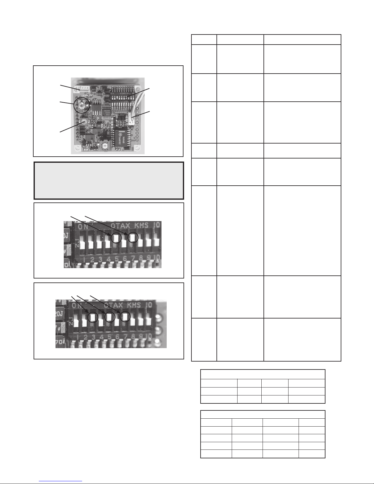
1. After completing installation of the housing, use the segmented
arms to adjust each camera to the desired viewing location
(Figure 4).
2. Once camera adjustments are made, place the dome back into
position to be sure cameras are not touching the inside of the
dome. If any do, adjust until they are clear.
Figure 4
CAMERA FOCUSING
1. Fine focusing:
Fixed Lens: Loosen the set screw in the lens mount and
manually rotate the lens until a clear picture is achieved. Once
the focus is set, retighten the set screw (Figure 5).
Fixed lens
FIXED AND FIXED VARI-FOCAL LENSES. There are no user
adjustable settings on these units (Figure 7).
BW Fixed and Vari-Focal
Figure 7
AUTO IRIS LENSES. The dip switches are factory set with AES
off and backlight compensation on (Figure 8). The auto iris is also
set at the factory, but an adjustment screw is included for use if
needed. See page 10 for instructions on adjusting Auto Iris.
BW Auto Iris
AES Default Off
Backlight
Compensation
Default On
Auto Iris
adjustment
screw
Figure 8
Set screw
Figure 5
Vari-Focal Lens: First, adjust the Magnification Lock Screw to the
desired magnification (telephoto to wide angle). Tighten the Lock
Screw. Next, adjust the Focus Lock Screw until a clear picture is
achieved. Tighten the Lock Screw (Figure 6).
Magnification lock screw
Figure 6
Auto Iris Lens:
NOTE: THE AUTO IRIS LENS IS SET AT THE FACTORY.
• IF YOU EXPERIENCE VIDEO TOO LIGHT OR DARK
AUTO IRIS ADJUSTMENT MAY BE NEEDED.
Focus lock screw
Fixed iris varifocal lens
SEE THE TROUBLESHOOTING SECTION FOR
ADJUSTMENT INFORMATION.
- 2 -
SERIAL NUMBERS BEGINNING WITH MC
The operational settings for the camera are defined by ten dip switch-
es located on the PC Board (Figure 9). Moving the switches to the on
position will activate each setting. Factory defaults are pictured below
(Figure 10 and 11).
Hi-Res Color, Fixed and Vari-focal fixed lenses
Factory
Use Only
Auto Iris
adjustment
screw
DO NOT
ADJUST
Figure 9
NOTE: Dip switches are factory pre-set for optimum performance.
In certain specific instances it may be necessary to adjust
one or more settings. Consult a qualified technician before
making any adjustments. A Dip Switch settings chart is
available on the next page.
FACTORY DEFAULT FIXED AND FIXED VARI-FOCAL LENSES:
Dip Switches 5 and 7 on, all others off.
Figure 10
FACTORY DEFAULT AUTO IRIS LENSES:
Dip Switches 3, 5 and 7 on, all others off.
Figure 11
Dip Switches
Connection to
Power Board
MC CAMERA DIP SWITCH SETTINGS CHART
SWITCH SETTING DEFINITION
1 Setting this switch to "On" and
2
3
4
5
6
7
8
9
10
Flickerless Mode
BLC (Back Light
Compensation)
MIRIS (Manual/
Electronic Iris
GAMMA
AGCMAX
(auto/gain control)
(Automatic White
Balance Control)
AW1
AW2
AW3
AEREF
AEME
switch 3 (MIRIS) to "Off" will
help to reduce the flicker in
fluorescent lights
Helps prevent an object from
being washed out when the
object is directly in front of a
light source.
When the switch is in the
on position the auto iris lens
controls the amount of light on
the chip. If in the off position
the light level is controlled
electronically.
Helps balance the contrast in
the picture.
Allows day/night cameras to
switch to b/w in low light conditions,
also helps with low light conditions
in standard and hi-res cameras
Used to help improve the
color quality of the camera
picture under different lighting conditions. The Factory Default is Switch 7 "ON",
switches 6 and 8 "OFF".
NOTE: ANY ADJUSTMENTS
TO THESE SETTINGS
SHOULD ONLY BE MADE
BY A QUALIFIED CCTV
TECHNICIAN
See examples below to help
with any adjustments.
This sets the electronic
convergence level. In the "off"
position the level is set to 100
IRE; in the "on" position the
user can set the level. Not
used with auto Iris
With this switch in the "On"
position users can manually
adjust the shutter speed and
gain using other switches See
the tables below for specific
settings
SHUTTER SPEED
Flickerless (1) BLC (2) MIRIS (3) Shutter Speed
On Off Off 1/100 Sec.
Off On Off 1/60 Sec.
GAIN
MIRIS (3) AEREF (9) AGCMAX (5) Gain
On Off Off 0dB
On On Off 6dB
On Off On 12dB
On On On 18dB
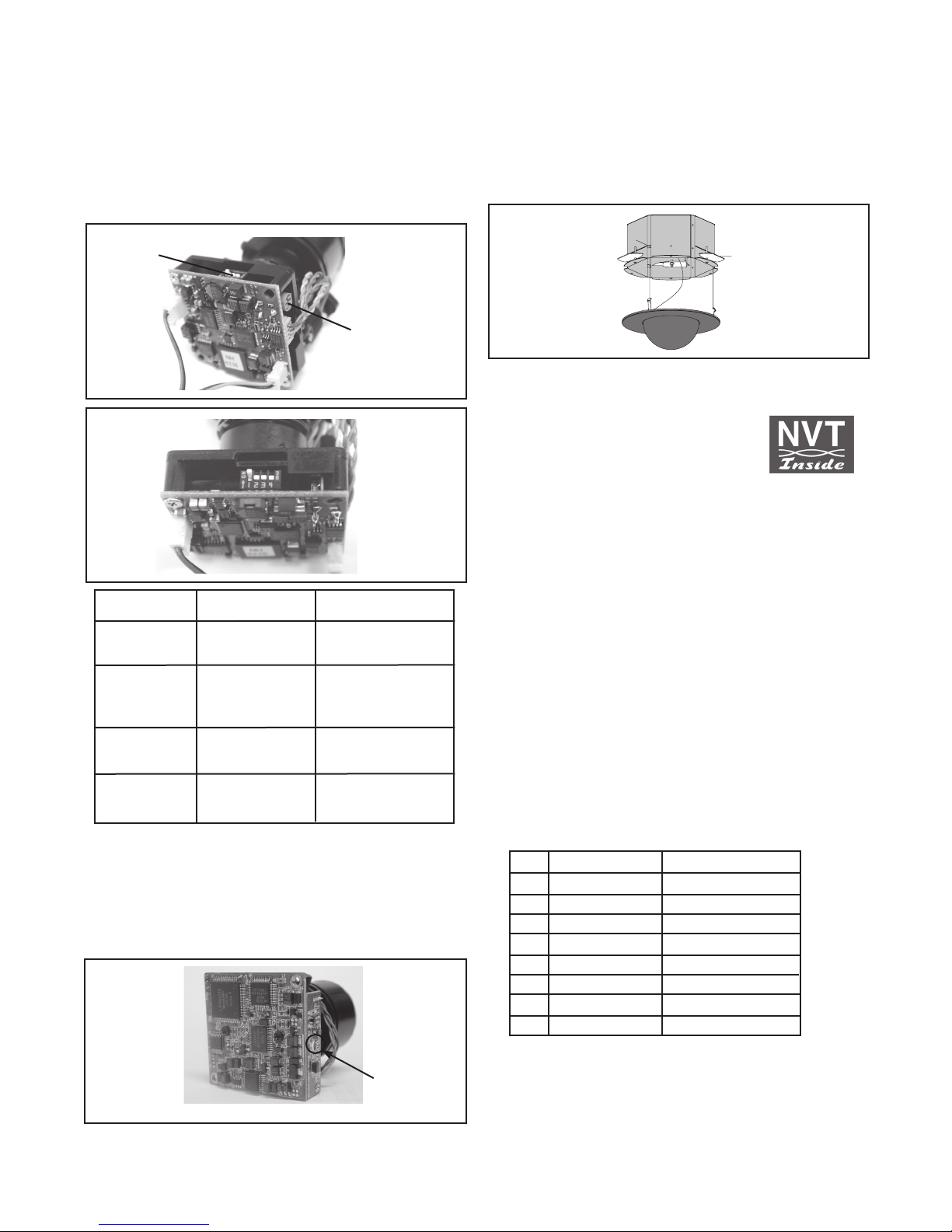
SERIAL NUMBERS BEGINNING WITH CB
NOTE: This hi-res color camera uses a 1/4" chip and a 3-6mm
auto iris lens. It is comparable to a 1/3" chip using a
4-9mm auto iris lens.
The operational settings are defined by four dip switches located on
the side of the PC Board (Figure 12 and 13). Moving the switches
to the UP position will activate specific settings. Refer to the chart
below.
Dip Switches
Auto Iris
Adjustment
Screw
Figure 12
Figure 13
COMPLETION OF INSTALLATION
Once all connections and adjustments have been made reattach the
trim ring/dome assembly by pressing in and sliding the three flat
springs into the housing (Figure 15). Make sure the springs are
aligned with the three spring slots. You will feel all three springs snap
into place when the dome is correctly secured into place. Rotate the
dome for final proper positioning of the liner and camera.
Figure 15
NVT INSTRUCTIONS
UNSHIELDED TWISTED PAIR
VIDEO WIRING
NOTE: The customer must purchase the Video Transceiver from
NVT. Part numbers are:
• NV-212A (500 ft.)
* NV-213A or NV-213A-M (1000 ft.)
• NV-652R, NV-862R, or NV-1662R (3000 ft.)
Dip Switch UP DOWN
1
(Iris) Auto Iris On Position for Fixed Lens
2
(Flickerless) Shutter speed Normal
fixed at 1/100 sec.
3 (Back Light ON Normal
Compensation
4
(Synch Mode) Internal Synch Line Lock Mode
SERIAL NUMBERS BEGINNING WITH CT
FIXED AND FIXED VARI-FOCAL LENSES. There are no user adjustable settings on these units (Figure 14)
AUTO IRIS LENSES: The auto iris can be adjusted if needed. See
the Troubleshooting section for instructions.
Auto Iris
adjustment
screw
Figure 14
The cameras included in the Q-View™ series have the option of
transmitting video signals to NVT receivers via unshielded twisted
pair cable. You must purchase the receiver separately. Instructions for
connecting the receiver end of the the unshielded twisted pair cable
will be included with the NVT receiver. Following are instructions for
connecting the unshielded twisted pair cables to the RJ45 (Cat. 5)
cable running outside your housing.
1. Video for all four cameras is contained in the one RJ45 (Cat. 5)
cable. An RJ45 female coupling is provided so that all connections
can be made with an RJ45 connector. The following is the wiring
diagram for the four twisted pair wires that are included with the
Cat. 5 cable.
PIN WIRE COLOR CAMERA NUMBER
1 White/Green Camera 1 +
2 Green Camera 1 -
3 White/Orange Camera 2 +
6 Orange Camera 2 -
5 White/Blue Camera 3 +
4 Blue Camera 3 -
7 White/Brown Camera 4 +
8 Brown Camera 4 -
 Loading...