

Moog Videolarm PV16, PV18 Installation And Operation Instructions Manual
© 2012, Moog Videolarm, Inc. All Rights Reserved
P V 1 6 / P V 1 8
PolEvators
Installation and Operation Instructions for the following models:
PV16N 16 Foot Lowering Pole includes exible shaft
PV18N 18 Foot Lowering Pole includes 16 foot aluminum pole with 2 foot
transformer base, nema box, transformer and exible shaft
Before attempting to connect or operate this product, please read these instructions completely.
www.moogvideolarm.com
81-IN5230
06-06-2012
IMPORTANT SAFEGUARDS SAFETY PRECAUTIONS
1 Read these instructions.
2 Keep these instructions.
3 Heed all warnings
4 Follow all instructions.
5 Do not use this apparatus near water.
6 Clean only with damp cloth.
7 Do not block any of the ventilation openings. Install in accordance with the
manufacturers instructions.
8 Cable Runs- All cable runs must be within permissible distance.
9 Mounting - This unit must be properly and securely mounted to a supporting
structure capable of sustaining the weight of the unit.
Accordingly:
a. The installation should be made by a qualified installer.
b. The installation should be in compliance with local codes.
c. Care should be exercised to select suitable hardware to install the unit, taking into
account both the composition of the mounting surface and the weight of the
unit.
10 Do not install near any heat sources such as radiators, heat registers, stoves, or other
apparatus ( including amplifiers) that produce heat.
11 Do not defeat the safety purpose of the polarized or grounding-type plug. A
polarized plug has two blades with one wider than the other. A grounding type
plug has two blades and a third grounding prong. The wide blade or the third
prong are provided for your safety. When the provided plug does not fit into your
outlet, consult an electrician for replacement of the obsolete outlet.
12 Protect the power cord from being walked on or pinched particularly at plugs,
convenience receptacles, and the point where they exit from the apparatus.
13 Only use attachment/ accessories specified by the manufacturer.
14 Use only with a cart, stand, tripod, bracket, or table specified by the manufacturer,
or sold with the apparatus. When a cart is used, use caution when moving the cart/
apparatus combination to avoid injury from tip-over.
15 Unplug this apparatus during lighting storms or when unused for long periods of time.
16 Refer all servicing to qualified service personnel. Servicing is required when the
apparatus has been damaged in any way, such as power-supply cord or plug is
damaged, liquid has been spilled of objects have fallen into the apparatus, the
apparatus has been exposed to rain or moisture, does not operate normally, or
has been dropped.
Be sure to periodically examine the unit and the supporting structure to make sure that the
integrity of the installation is intact. Failure to comply with the foregoing could result in the
unit separating from the support structure and falling, with resultant damages or injury to
anyone or anything struck by the falling unit.
UNPACKING
Unpack carefully. Electronic components can be
damaged if improperly handled or dropped. If an item
appears to have been damaged in shipment, replace
it properly in its carton and notify the shipper.
Be sure to save:
1 The shipping carton and packaging material.
They are the safest material in which to make
future shipments of the equipment.
2 These Installation and Operating Instructions.
SERVICE
If technical support or service is needed, contact us
at the following number:
CAUTION: TO REDUCE THE RISK OF
ELECTRIC SHOCK, DO NOT REMOVE
COVER ( OR BACK). NO USER- SERVICE-
ABLE PARTS INSIDE. REFER SEVICING TO
QUALIFIED SERVICE PERSONNEL.
The lightning flash with an arrowhead
symbol, within an equilateral triangle, is
intended to alert the user to the presence
of non-insulated “dangerous voltage”
within the product’s enclosure that may be
of sufficient magnitude to constitute a risk
to persons.
Este símbolo se piensa para alertar al usuario a la
presencia del “voltaje peligroso no-aisIado” dentro del
recinto de los productos que puede ser un riesgo de
choque eléctrico.
Ce symbole est prévu pour alerter I’utilisateur à la
presence “de la tension dangereuse” non-isolée dans la
clôture de produits qui peut être un risque de choc
électrique.
Dieses Symbol soll den Benutzer zum Vorhandensein der
nicht-lsolier “Gefährdungsspannung” innerhalb der
Produkteinschließung alarmieren die eine Gefahr des
elektrischen Schlages sein kann.
Este símbolo é pretendido alertar o usuário à presença
“di tensão perigosa non-isolada” dentro do cerco dos
produtos que pode ser um risco de choque elétrico.
Questo simbolo è inteso per avvertire I’utente alla
presenza “di tensione pericolosa” non-isolata all’interno
della recinzione dei prodotti che può essere un rischio di
scossa elettrica
The exclamation point within an equilateral
triangle is intended to alert the user to
presence of important operating and
maintenance (servicing) instructions in the
literature accompanying the appliance.
Este símbolo del punto del exclamation se piensa para
alertar al usuario a la presencia de instrucciones
importantes en la literatura que acompaña la
aplicación.
Ce symbole de point d’exclamation est prévu pour
alerter l’utilisateur à la presence des instructions
importantes dans la littérature accompagnant
l’appareil.
Dieses Ausruf Punktsymbol soll den Benutzer zum
Vorhandensein de wichtigen Anweisungen in der
Literatur alarmieren, die das Gerät begleitet.
Este símbolo do ponto do exclamation é pretendido
alertar o usuário à presença de instruções importantes
na literatura que acompanha o dispositivo.
Questo simbolo del punto del exclamaton è inteso per
avvertire l’utente alla presenza delle istruzioni importanti
nella letteratura che accompagna l'apparecchio.
CAUTION
RISK OF ELECTRIC SHOCK
DO NOT OPEN
.
TECHNICAL SUPPORT
AVAILABLE 24 HOURS
1- 800 - 554 -1124

Limited Warranty for Moog Videolarm Products
Moog Videolarm warrants these products to be free from defects in material or workmanship as follows:
PRODUCT CATEGORY PARTS \ LABOR
All Enclosures and Electronics* Five (5) Years
Poles/PolEvators™/CamEvator Three (3) Years
Warrior Series™/Q-View™/IR Illuminators Five (5) Years
SView Series™ Five (5) Years **6 months if used in auto scan/tour operation
Controllers Five (5) Years
Power Supplies Five (5) Years
EcoKit Three (3) Years
Accessory Brackets Five (5) Years
Liberty Dome Three (3) Years
*DeputyDome™, NiteTrac™, Igloo Dome, PurgeDome™ Three (3) Years **6 months if used in auto scan/tour operation
During the labor warranty period, to repair the Product, Purchaser will either return the defective product, freight prepaid, or deliver it to Moog Videolarm
Inc. Decatur GA. The Product to be repaired is to be returned in either its original carton or a similar package affording an equal degree of protection with
a RMA # (Return Materials Authorization number) displayed on the outer box or packing slip. To obtain a RMA# you must contact our Technical Support
Team at 800.554.1124, extension 101. Moog Videolarm will return the repaired Product freight prepaid to Purchaser. Moog Videolarm is not obligated to
provide Purchaser with a substitute unit during the warranty period or at any time. After the applicable warranty period, Purchaser must pay all labor and/or
parts charges.
The limited warranty stated in these product instructions is subject to all of the following terms and conditions.
TERMS AND CONDITIONS
1. NOTIFICATION OF CLAIMS: WARRANTY SERVICE: If Purchaser believes that the Product is defective in material or workmanship, then written notice with an
explanation of the claim shall be given promptly by Purchaser to Moog Videolarm. All claims for warranty service must be made within the warranty period.
If after investigation Moog Videolarm determines the reported problem was not covered by the warranty, Purchaser shall pay Moog Videolarm for the cost of
investigating the problem at its then prevailing per incident billable rate. No repair or replacement of any Product or part thereof shall extend the warranty period
of the entire Product. The speci c warranty on the repaired part only shall be in effect for a period of ninety (90) days following the repair or replacement of that
part or the remaining period of the Product parts warranty, whichever is greater.
2. EXCLUSIVE REMEDY: ACCEPTANCE: Purchaser’s exclusive remedy and Moog Videolarm’s sole obligation is to supply (or pay for) all labor necessary to repair any
Product found to be defective within the warranty period and to supply, at no extra charge, new or rebuilt replacements for defective parts.
3. EXCEPTIONS TO LIMITED WARRANTY: Moog Videolarm shall have no liability or obligation to Purchaser with respect to any Product requiring service during the
warranty period which is subjected to any of the following: abuse, improper use, negligence, accident, lightning damage or other acts of God (i.e., hurricanes,
earthquakes), modi cation, failure of the end-user to follow the directions outlined in the product instructions, failure of the end-user to follow the maintenance
procedures recommended by the International Security Industry Organization, written in product instructions, or recommended in the service manual for the
Product. Furthermore, Moog Videolarm shall have no liability where a schedule is speci ed for regular replacement or maintenance or cleaning of certain parts
(based on usage) and the end-user has failed to follow such schedule; attempted repair by non-quali ed personnel; operation of the Product outside of the
published environmental and electrical parameters, or if such Product’s original identi cation (trademark, serial number) markings have been defaced, altered,
or removed. Moog Videolarm excludes from warranty coverage Products sold AS IS and/or WITH ALL FAULTS and excludes used Products which have not
been sold by Moog Videolarm to the Purchaser. All software and accompanying documentation furnished with, or as part of the Product is furnished “AS IS”
(i.e., without any warranty of any kind), except where expressly provided otherwise in any documentation or license agreement furnished with the Product. Any
cost associated with removal of defective product and installation of replacement product is not included in this warranty.
4. PROOF OF PURCHASE: The Purchaser’s dated bill of sale must be retained as evidence of the date of purchase and to establish warranty eligibility.
DISCLAIMER OF WARRANTY
EXCEPT FOR THE FOREGOING WARRANTIES, Moog Videolarm HEREBY DISCLAIMS AND EXCLUDES ALL OTHER WARRANTIES, EXPRESS OR IMPLIED,
INCLUDING, BUT NOT LIMITED TO ANY AND/OR ALL IMPLIED WARRANTIES OF MERCHANTABILITY, FITNESS FOR A PARTICULAR PURPOSE AND/OR
ANY WARRANTY WITH REGARD TO ANY CLAIM OF INFRINGEMENT THAT MAY BE PROVIDED IN SECTION 2-312(3) OF THE UNIFORM COMMERCIAL
CODE AND/OR IN ANY OTHER COMPARABLE STATE STATUTE. Moog Videolarm HEREBY DISCLAIMS ANY REPRESENTATIONS OR WARRANTY THAT
THE PRODUCT IS COMPATIBLE WITH ANY COMBINATION OF NON-Moog Videolarm PRODUCTS OR NON-Moog Videolarm RECOMMENDED PRODUCTS
PURCHASER MAY CHOOSE TO CONNECT TO THE PRODUCT.
LIMITATION OF LIABILITY
THE LIABILITY OF Moog Videolarm, IF ANY, AND PURCHASER’S SOLE AND EXCLUSIVE REMEDY FOR DAMAGES FOR ANY CLAIM OF ANY KIND
WHATSOEVER, REGARDLESS OF THE LEGAL THEORY AND WHETHER ARISING IN TORT OR CONTRACT, SHALL NOT BE GREATER THAN THE ACTUAL
PURCHASE PRICE OF THE PRODUCT WITH RESPECT TO WHICH SUCH CLAIM IS MADE. IN NO EVENT SHALL Moog Videolarm BE LIABLE TO PURCHASER
FOR ANY SPECIAL, INDIRECT, INCIDENTAL, OR CONSEQUENTIAL DAMAGES OF ANY KIND INCLUDING, BUT NOT LIMITED TO, COMPENSATION,
REIMBURSEMENT OR DAMAGES ON ACCOUNT OF THE LOSS OF PRESENT OR PROSPECTIVE PROFITS OR FOR ANY OTHER REASON WHATSOEVER.
IMPORTANT SAFEGUARDS
Per installazione del parafulmine PV1 vedi la manuale
!!
proceeding,and heed all cautions.
1. At 150 lbs. the PolEvator™ is capable of being erected
by 2 adults with not lifting equipment. However, to
prevent personal injury or damage to the pole,
EXTREME CAUTION should be used when lifting the
pole.
2. DO NOT erect the pole in high wind, during periods of
lightning, or in icy conditions.
3. DO NOT operate the pole carriage when the pole is in
a horizontal position.
Lea por favor estas instrucciones cuidadosamente
antes el procedimiento, y presta atención a todas
las precauciones.
1. En 150 libras. el PolEvator™ es capaz de la erección por 2
adultos con el equipo de elevación. Sin embargo, a
prevenga los daños corporales o el daño al poste, La
PRECAUCIÓN EXTREMA debe ser utilizada al levantar
poste.
2. No erija el poste en fuerte viento, durante períodos de
relámpago, o en condiciones heladas.
3. No funcione el carro del poste cuando el poste está
adentro una posición horizontal.
Veuillez lire ces instructions soigneusement avant la
marche à suivre, et observent toutes les attentions.
1. À 150 livres. le PolEvator™ est capable de l'érection par 2 adultes
avec l'équipement de levage. Cependant, à empêchez le
dommage corporel ou les dommages au poteau,
L'ATTENTION EXTRÊME devrait être employée en se soulevant
poteau.
2. N'érigez pas le poteau en fort vent, au cours des périodes de
foudre, ou en conditions glaciales.
3. N'actionnez pas le chariot de poteau quand le poteau est
dedans une position horizontale.
Lesen Sie bitte diese Anweisungen sorgfältig vorher
das Verfahren und beachten alle Vorsichtsmaßnahmen.
1. Bei 150 lbs. das PolEvator™ ist zu aufgerichtet werden fähig durch
2 Erwachsene mit nicht Hebezeug. Jedoch zu verhindern Sie
Personenschaden oder Schaden des Pfostens, EXTREME
VORSICHT sollte beim Anheben verwendet werden Pfosten.
2. Richten Sie den Pfosten im starken Wind, NICHT während der
Zeiträume von auf Blitz oder in den eisigen Bedingungen.
3. Betreiben Sie NICHT den Pfostenwagen, wenn der Pfosten innen
ist eine horizontale Position.
Leia por favor estas instruções com cuidado antes
prosiguer, e observa todos os cuidados.
1. Em 150 libras. o PolEvator™ é capaz da erecção por 2 adultos
com equipamento de levantamento. Entretanto, a impeça
ferimento pessoal ou dano ao pólo, O CUIDADO EXTREMO
deve ser usado ao levantar pólo.
2. Não erija o pólo no vento forte, durante períodos de relâmpago,
ou em circunstâncias geladas.
3. Não opere a carruagem do pólo quando o pólo está dentro
uma posição horizontal.
Legga prego con attenzione prima queste istruzioni
la continuazione e fa attenzione a tutte le avvertenze.
1. A 150 libbre. il PolEvator™ è capace di costruzione da 2 adulti
con l'apparecchiatura di sollevamento. Tuttavia, a
prevenga danni la ferita personale o to il palo,
L'ATTENZIONE ESTREMA dovrebbe essere usata quando
alza palo.
2. Non eriga il palo in vento forte, durante i periodi di lampo, o
nelle circostanze ghiacciate.
3. Non faccia funzionare il carrello del palo quando il palo è dentro
una posizione orizzontale.
Please read these instructions carefully before
English
Español
Français
Deutsch
Portuguese
Italiano
Note: For installation of PV1 Lightning Rod see Instruction manual
English
81-IN5256.
Nota: Para la instalación del pararrayos PV1 vea la instrucción
Español
81-IN5256 manual.
Note : Pour l'installation du paratonnerre PV1 voir l'instruction
Français
81-IN5256 manuel.
Anmerkung: Für Installation des Blitzableiters PV1 sehen Sie
Deutsch
Anweisung manuelles 81-IN5256.
Nota: Para a instalação PV1 do relâmpago Rod veja a instrução
Portuguese
81-IN5256 manual.
Nota:
Italiano
d'istruzione 81-IN5256.
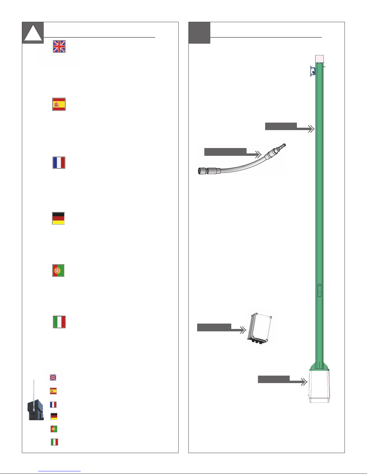
Flexible Shaft
**
NEMA Box
Content of Box
16’ Pole
2’ Base
**
** NEMA Box and Base included with
PV18N ONLY
1 2
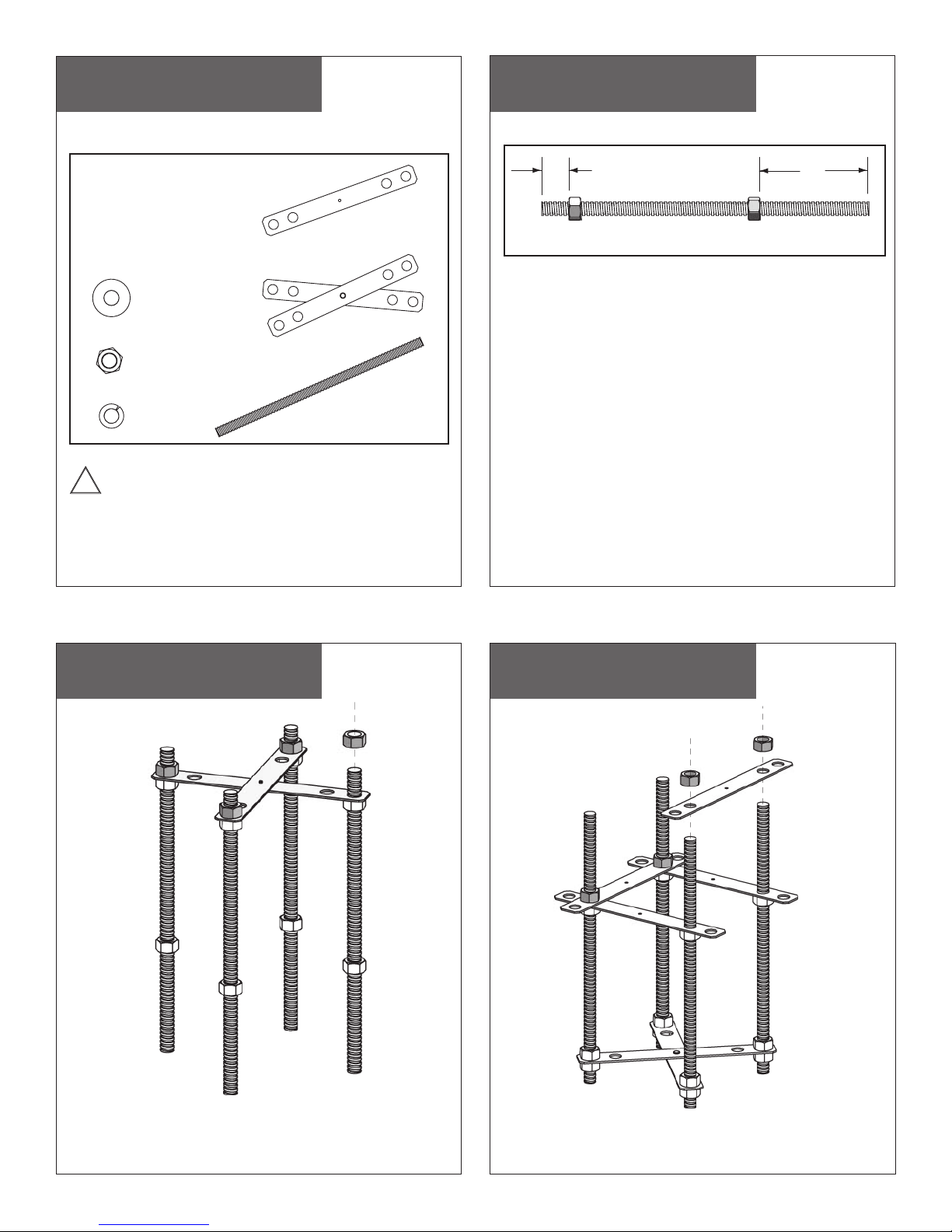
Anchor Jig Assembly
Anchor Jig Kit Parts List
Sold Separately
Anchor Jig Assembly
Sold Separately
Figure 1
Single Straps (4)
3/4" Flat Washers (4)
3/4" - 10 Hex Nut (20)
Lock
Washers (4)
CAUTION: To prevent corrosion; never mix galvanized hardware
!!
with stainless steel hardware!
Cross Strap (1)
3/4" - 10 Bolts (4)
1 "
1 1/2"
1. Thread two (2) nuts onto each of the (4) bolts (Figure 1). The end
with 6" of clearance will be the top of the Anchor Jig, the end with
1 1/2" clearance will be the bottom.
NOTE: Because of surface conditions it may be necessary to use
leveling nuts.
6"*
3
Anchor Jig Assembly
Figure 2
Sold Separately Sold Separately
Place the short end of each Bolt into the outside holes of the
Cross Strap. PlaceHex Nuts onto each Bolt and fi nger tighten.
4
Turn the Anchor Jig over and place Single Straps over the Bolts.
Use the inside hole of each strap. Place Hex Nuts
Bolt and fi nger tighten.
Anchor Jig Assembly
Figure 3
onto each
 Loading...