

Moog Videolarm POD8C, PID8C, POD8CFW, POD8CW, POD8CF Product Instructions

Manufactured by:
Before attempting to connect or operate this product, please read these instructions completely.
MODEL: Outdoor Dome Housing
POD8C(W), POD8CF(W), PID8C
81-IN3074
5/19/04
for
PRODUCT INSTRUCTIONS
INSTALLING QUICK RELEASE BRACKET AND PAN/TILT
CAMERA ASSEMBLY (ALL MODELS)
ELECTRICAL SPECIFICATIONS (OUTDOOR ONLY):
Power 24VAC, Class 2 Only
!
52 watts at 24 VAC (accessories)
Heater: 50 watts
Blower: 1.7 watts
Input Connectors (outdoor units):
BNC
(2) 4 position Molex connectors (power)
(1) Phone style plug (control)
NOTE: This unit is designed for operation in an
upright position. Installing the unit
upside down may cause damage to the
internal equipment, and will void the war-
ranty.
GENERAL INSTRUCTIONS:
Tools Required: .100" Flat Head Screwdriver
Phillips Head Screwdriver
PREPARING PENDANT MOUNT BRACKET FOR POD8C
(For wall mount, POD8CW, see page 3)
1. Open the housing by loosening the (3) captive screws located
on the housing ring next to the lower clear dome. Be careful
not to back these all the way out. Twist the dome slightly in a
counterclockwise motion to remove (Figure 2).
Loosen screws only,
do not remove
Remove dome by
twisting coun ter clock wise
Figure 2
2. Install the pan/tilt unit quick- release bracket. It is recom-
mended that this be done before installing the housing.
3. Spacers are provided to adjust the level of the WV-CS854
camera. Attach the spacers, two-high, to the main housing
bracket (Figure 3).
1. Carefully remove the housing from the packaging material.
Check to be sure all parts are present.
2. This unit includes a 1 1/2" NPT housing coupling for a standard
1 1/2" NPT pipe. The POD8C can be used with other brackets
designed with 1 1/2" male pipe threads, such as the Panasonic
WM20G and PWM30G brackets.
3. Attach the housing coupling to the bracket or pendant pipe
(Figure 1).
NOTE: Pipe threads should be clean and rust free. Use a
sealer (such as Tefl on™ tape or silicone sealer) on the
threads.
Add thread
sealing tape
Figure 1
Be sure the bracket is properly and securely mounted
to a supporting structure capable of rigidly holding the
!
weight of the entire unit.
Figure 3
2525 Park Central Blvd. • Decatur, Ga 30035 • (770) 987-7550 • 800-554-1124 U.S. & Canada • www.videolarm.com • Fax 800-826-0366
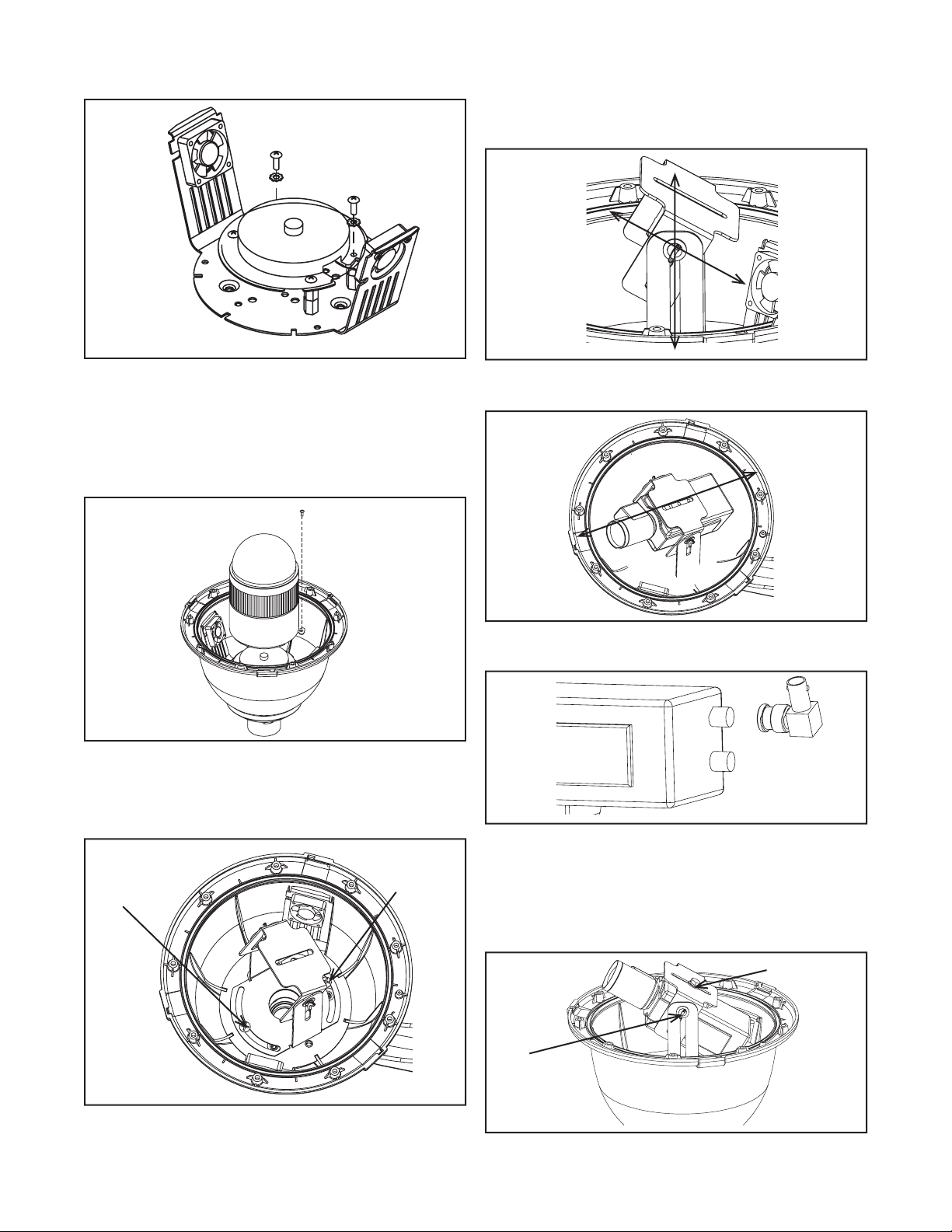
4. Connect the quick-release bracket to the spacers using the (4) 8 x
32 x 1/2" bolts and #8 star washers (Figure 4).
2. Tilt and height adjustments can be made using the two screws
located on the upper portion of the fi xed camera bracket. Loosen-
ing the screws allows the bracket itself to slide up and down the
bracket arms (height adjustment) and back and forth on the cam-
era bracket (tilt). Adjust to the desired location (Figure 7).
Figure 4
5. Attach the unitized camera to the quick-release bracket. Secure
the safety screw (Figure 5). Connect the BNC, power, control,
and alarm cables. Make sure all wiring is clear of the blowers and
heater on the housing bracket. Use the cable tie provided to
secure the wires and connectors.
NOTE: Remove the plastic dome from the WV-CS854 unitized
camera to ensure the best optical picture.
Safety Screw
Figure 5
INSTALLING FIXED CAMERA BRACKET (ALL MODELS)
Figure 7
3. The camera can also be adjusted back and forth via the slot
located on the bottom of the bracket (Figure 8).
Figure 8
NOTE: A 90˚ BNC connector is included in the packet to assist in
fi tting the camera (Figure 9).
1. Loosen the two pan adjustment screws and rotate the bracket to
the desired viewing location.
Pan
adjustment
screw
Pan
adjustment
screw
Figure 6
Figure 9
4. Attach the camera to the bracket using the 1/4-20 hex bolt
provided. Make fi nal adjustments and lock down the pan, tilt, and
height adjustment screws (Figure 10).
IMPORTANT NOTE: Put the dome in place to assure the camera
does not touch it. To reattach the dome you must twist it, if the
dome comes in contact with the camera its position could change.
1/4-20 hex bolt
Tilt
adjustment
screw
Figure 10
- 2 -

INSTALLING THE HOUSING ASSEMBLY
FOR WALL MOUNT POD8CW (Figure 11)
1. A wall mount bracket comes standard with this unit, and a
template is included to use as a guide for mounting the bracket
to a wall. Choose the desired location for installation and mark
the drill holes using the template. Screw (2) bolts (not
provided) about 3/4 of the way into the (2) top holes. Run
approximately 8" of wiring out of the wall.
2. Open the access door on the bottom of the wall mount by
loosening the screw nearest the mounting plate.
3. Slip the housing onto the top (2) bolts and pull the wires from the
wall through the rectangular hole in the wall mount bracket.
Screw bolts and washers through the bottom (2) holes and
secure. Remove the top (2) bolts, add washers, and reattach,
tightening completely.
4. Attach the wires from the wall to the connector provided, using the
wiring color code chart as a guide.
5. Once all wiring connections are made, place the wires inside the
wall mount bracket and close the access door. Secure with the
screw removed earlier.
6. Clean the outside of the dome.
Twist and
Secure
Figure 12
Wiring Color Code
Power and Control Inputs
POD8C
CAMERA POWER
1 24 VAC Live Black
2 24 VAC Live White
3 Green Green
4 Not Used
ACCESSORY POWER
1 24 VAC Live Red
2 24 VAC Live White
3 Green Green
4 Not Used
Loosen screw to open
access door
Figure 11
FOR PENDANT MOUNT, POD8C (Figure 12)
1. Mount the housing assembly to the mounting bracket and
housing coupling. A safety cable is included with the housing to
temporarily hold it while making wiring connections. Loop the
safety cable over one of the set screws on the housing coupling
and make the appropriate connections using the (2) screw-down
connectors supplied.
2. Undo the safety cable and twist the housing onto the housing
coupling. Secure all (3) setscrews provided on the housing
coupling (Figure 4).
Pan/Tilt Unit Only
CONTROL
1 Ground Brown
2 TXB (RS485) Red
3 TXA (RS485) Orange
4 RXB (RS485) Yellow
5 RXB (RS485) Green
ALARM IN (8-pin)
1 Alarm In 1 Black
2 Ground Brown
3 Alarm In 2 Red
4 Ground Orange
5 Alarm In 3 Yellow
6 Ground Light blue or green
7 Alarm In 4 Blue
8 Ground Purple
ALARM OUT (4-pin)
1 Alarm Out 1 Gray
2 Ground White
3 Alarm Out 2 Pink
4 Ground Yellow, Green, or Light blue
3. Clean the outside of the dome.
- 3 -
 Loading...