

Moog Videolarm DDW10CR2, PDDW10CN2, PDDW10CR, DDW10CR1, PDDW10CR1 Installation And Operation Instructions Manual
© 2009-2010, Moog Videolarm, Inc. All Rights Reserved
© 2009-2010, Videolarm, Inc. All Right Reserved
Product Information for
|
1 . 8 0 0 . 5 5 4 . 1 1 2 4
w w w .v i d e o l a r m .c o m
IP Ready Software
|
D e p u t y D o m e
Bullet-Resistant Standard / Pressurized Dome
Installation and Operation Instructions for the following models:
DDW10CR1 DeputyDome™ Series, 10-gauge Steel Bullet-Resistant Outdoor
dome PTZ Camera System with 26x Day/Night Camera, onboard receiver
/driver, 120VAC heater Tough enough to stop a 9mm bullet
PDDW10CR1 (Pressurized Version)
DeputyDome™ Series, 10-gauge Steel Bullet-Resistant Outdoor
dome PTZ Camera System with 26x Day/Night Camera, onboard receiver
/driver, 120VAC heater Tough enough to stop a 9mm bullet
Before attempting to connect or operate this product,
please read these instructions completely.
www.videolarm.com
CERTIFIED
81-IN5210
10-07-2010
IMPORTANT SAFEGUARDS SAFETY PRECAUTIONS
1 Read these instructions.
2 Keep these instructions.
3 Heed all warnings
4 Follow all instructions.
5 Do not use this apparatus near water.
6 Clean only with damp cloth.
7 Do not block any of the ventilation openings. Install in accordance with the
manufacturers instructions.
8 Cable Runs- All cable runs must be within permissible distance.
9 Mounting - This unit must be properly and securely mounted to a supporting
structure capable of sustaining the weight of the unit.
Accordingly:
a. The installation should be made by a qualified installer.
b. The installation should be in compliance with local codes.
c. Care should be exercised to select suitable hardware to install the unit, taking into
account both the composition of the mounting surface and the weight of the
unit.
10 Do not install near any heat sources such as radiators, heat registers, stoves, or other
apparatus ( including amplifiers) that produce heat.
11 Do not defeat the safety purpose of the polarized or grounding-type plug. A
polarized plug has two blades with one wider than the other. A grounding type
plug has two blades and a third grounding prong. The wide blade or the third
prong are provided for your safety. When the provided plug does not fit into your
outlet, consult an electrician for replacement of the obsolete outlet.
12 Protect the power cord from being walked on or pinched particularly at plugs,
convenience receptacles, and the point where they exit from the apparatus.
13 Only use attachment/ accessories specified by the manufacturer.
14 Use only with a cart, stand, tripod, bracket, or table specified by the manufacturer,
or sold with the apparatus. When a cart is used, use caution when moving the cart/
apparatus combination to avoid injury from tip-over.
15 Unplug this apparatus during lighting storms or when unused for long periods of time.
16 Refer all servicing to qualified service personnel. Servicing is required when the
apparatus has been damaged in any way, such as power-supply cord or plug is
damaged, liquid has been spilled of objects have fallen into the apparatus, the
apparatus has been exposed to rain or moisture, does not operate normally, or
has been dropped.
Be sure to periodically examine the unit and the supporting structure to make sure that the
integrity of the installation is intact. Failure to comply with the foregoing could result in the
unit separating from the support structure and falling, with resultant damages or injury to
anyone or anything struck by the falling unit.
UNPACKING
Unpack carefully. Electronic components can be
damaged if improperly handled or dropped. If an item
appears to have been damaged in shipment, replace
it properly in its carton and notify the shipper.
Be sure to save:
1 The shipping carton and packaging material.
They are the safest material in which to make
future shipments of the equipment.
2 These Installation and Operating Instructions.
SERVICE
If technical support or service is needed, contact us
at the following number:
CAUTION: TO REDUCE THE RISK OF
ELECTRIC SHOCK, DO NOT REMOVE
COVER ( OR BACK). NO USER- SERVICE-
ABLE PARTS INSIDE. REFER SEVICING TO
QUALIFIED SERVICE PERSONNEL.
The lightning flash with an arrowhead
symbol, within an equilateral triangle, is
intended to alert the user to the presence
of non-insulated “dangerous voltage”
within the product’s enclosure that may be
of sufficient magnitude to constitute a risk
to persons.
Este símbolo se piensa para alertar al usuario a la
presencia del “voltaje peligroso no-aisIado” dentro del
recinto de los productos que puede ser un riesgo de
choque eléctrico.
Ce symbole est prévu pour alerter I’utilisateur à la
presence “de la tension dangereuse” non-isolée dans la
clôture de produits qui peut être un risque de choc
électrique.
Dieses Symbol soll den Benutzer zum Vorhandensein der
nicht-lsolier “Gefährdungsspannung” innerhalb der
Produkteinschließung alarmieren die eine Gefahr des
elektrischen Schlages sein kann.
Este símbolo é pretendido alertar o usuário à presença
“di tensão perigosa non-isolada” dentro do cerco dos
produtos que pode ser um risco de choque elétrico.
Questo simbolo è inteso per avvertire I’utente alla
presenza “di tensione pericolosa” non-isolata all’interno
della recinzione dei prodotti che può essere un rischio di
scossa elettrica
The exclamation point within an equilateral
triangle is intended to alert the user to
presence of important operating and
maintenance (servicing) instructions in the
literature accompanying the appliance.
Este símbolo del punto del exclamation se piensa para
alertar al usuario a la presencia de instrucciones
importantes en la literatura que acompaña la
aplicación.
Ce symbole de point d’exclamation est prévu pour
alerter l’utilisateur à la presence des instructions
importantes dans la littérature accompagnant
l’appareil.
Dieses Ausruf Punktsymbol soll den Benutzer zum
Vorhandensein de wichtigen Anweisungen in der
Literatur alarmieren, die das Gerät begleitet.
Este símbolo do ponto do exclamation é pretendido
alertar o usuário à presença de instruções importantes
na literatura que acompanha o dispositivo.
Questo simbolo del punto del exclamaton è inteso per
avvertire l’utente alla presenza delle istruzioni importanti
nella letteratura che accompagna l'apparecchio.
CAUTION
RISK OF ELECTRIC SHOCK
DO NOT OPEN
.
TECHNICAL SUPPORT
AVAILABLE 24 HOURS
1- 800 -554 -1124
LIMITED WARRANTY
FOR VIDEOLARM INC. PRODUCTS
VIDEOLARM INC. warrants this Product to be free fromdefectsin material or workmanship,as follows:
PRODUCTCATEGORY PARTS LABOR
All Enclosuresand Electronics Five (5) Years Five (5) Years
Pan/Tilts Three (3) Years **6 months if usedin autoscan Three (3) Years **6 months if used in autoscan
Poles/PoleEvators Three (3) Years Three (3) Years
Warrior/Q-View/I.R.Illuminators Five (5) Years Five (5) Years
Controllers Five (5) Years Five (5) Years
PowerSupplies Five (5) Years Five (5) Years
AccessoryBrackets Five (5) Years Five (5) Years
During the labor warranty period, to repair the Product,Purchaserwill either return the defective product,freight prepaid, or deliver it to Videolarm Inc.
Decatur GA.The Productto be repaired isto be returned in either its original carton or a similar package
an equal degree of protection with a
RMA# (Return Materials Authorization number) displayed on the outer box or packing slip. Toobtain a RMA#you must contact our Technical Support
Teamat 800.554.1124,extension 101.Videolarm will return the repaired Productfreight prepaid to Purchaser.Videolarm is not obligated to provide
Purchaserwith a substitute unit during the warranty period or at any time. After the applicable warranty period, Purchasermust pay all labor and/or
parts charges.
1.NOTIFICATIONOF CLAIMS:WARRANTYSERVICE: If Purchaser believes that the Product is defective in material or workmanship, then written notice
with an explanation of the claim shall be given promptly by Purchaser toVideolarm but all claims for warranty service must be made within the
warranty period. If after investigation Videolarm determines that the reported problem was not covered by the warranty, P
urchaser shall pay Videolarm
for the cost of investigating the problem at its then prevailing per incident billable rate. No repair or replacement of any Product or part thereof shall
extend the warranty period as to the entire Product. The
warranty on the repaired part only shall be in for a period of ninety (90) days
following the repair or replacement of that part or the remaining period of the Product parts warranty, whichever is greater.
2.EXCLUSIVE REMEDY: ACCEPTANCE:Purchaser’s exclusive remedy and Videolarm’s sole obligation is to supply (or pay for) all labor necessary to repair
any Product found to be defective within the warranty period and to supply, at no extra charge, new or rebuilt replacements for defective parts.
3.EXCEPTIONS TO LIMITED WARRANTY: Videolarm shall have no liability or obligation to Purchaser with respect to any Product requiring service
during the warranty period which is subjected to any of the following: abuse, improper use: negligence, accident, lightning damage or other acts
of God (i.e., hurricanes, earthquakes),
failure of the end-user to follow the directions outlined in the product instructions, failure of the
end-user to follow the maintenance procedures recommended by the International Security Industry Organization, written in product instructions,
or recommended in the service manual for the Product. Furthermore, Videolarm shall have no liability where a schedule is
for regular
replacement or maintenance or cleaning of certain parts (based on usage) and the end-user has failed to follow such schedule; attempted repair by
personnel; operation of the Product outside of the published environmental and electrical parameters, or if such Product’s original
(trademark, serial number) markings have been defaced, altered, or removed. Videolarm excludes from warranty coverage Products sold
AS IS and/or WITH ALL FAULTS and excludes used Products which have not been sold byVideolarm to the Purchaser. All software and accompanying
documentation furnished with, or as part of the Product is furnished “AS IS” (i.e., without any warranty of any kind), except where expressly provided
otherwise in any documentation or license agreement furnished with the Product.
4.PROOF OF PURCHASE:The Purchaser’s dated bill of sale must be retained as evidence of the date of purchase and to establish warranty eligibility.
DISCLAIMEROF WARRANTY
EXCEPT FOR THE FOREGOINGWARRANTIES,VIDEOLARM HEREBY DISCLAIMS AND EXCLUDES ALL OTHER WARRANTIES, EXPRESS OR IMPLIED,
INCLUDING, BUT NOT LIMITEDTO ANY AND/OR ALL IMPLIED WARRANTIES OF MERCHANTABILITY, FITNESS FOR A PARTICULAR PURPOSE AND/OR ANY WARRANTY WITH
REGARD TO ANY CLAIM OF INFRINGEMENTTHAT MAY BE PROVIDED IN SECTION 2-312(3) OF
THE UNIFORM COMMERCIAL CODE AND/OR IN ANY OTHER COMPARABLE
STATE STATUTE.VIDEOLARM HEREBY DISCLAIMS ANY REPRESENTATIONS ORWARRANTY THAT THE PRODUCT IS COMPATIBLE WITH ANY COMBINATION OF NON-VIDEOLARM
PRODUCTS OR NON-VIDEOLARM RECOMMENDED PRODUCTS PURCHASER CHOOSES TO CONNECT TO PRODUCT.
LIMITATION OF LIABILITY
THE LIABILITY OF VIDEOLARM, IF ANY, AND PURCHASER’S SOLE AND EXCLUSIVE REMEDY FOR DAMAGES FOR ANY CLAIM OF ANY KIND
WHATSOEVER, REGARDLESS OFTHE LEGAL THEORY ANDWHETHER ARISING IN TORT OR CONTRACT, SHALL NOT BE GREATER THAN THE ACTUAL PURCHASE PRICE OF THE
PRODUCT WITH RESPECT TO WHICH SUCH CLAIM IS MADE. IN NO EVENT SHALL VIDEOLARM BE LIABLE TO PURCHASER FOR ANY SPECIAL, INDIRECT, INCIDENTAL, OR
CONSEQUENTIAL DAMAGES OF ANY KIND INCLUDING, BUT NOT LIMITED TO, COMPENSATION, REIMBURSEMENT OR DAMAGES ON ACCOUNT OF THE LOSS OF PRESENT
OR PROSPECTIVE PROFITS OR FOR ANY OTHER REASON WHATSOEVER.
/tour operation
/tour operation
**6 months if usedin autoscan
/tour operation
**6 months if usedin autoscan
/tour operation
SView Series Five (5) Years
Five (5) Years
The limited warranty stated in these product instructions is subject to all of the following terms and conditions:
TERMS AND CONDITIONS
Electrical Specifications
!!
English
Español
(Camera with hardwire pan/tilt)
Power Source & Power Consumption
(includes: heater, blower and camera)
DDW10CR1 (N) 115 VAC, 90 vA, 0.8 Amps
DDW10CR2 (N) 24 VAC, (Class 2), 90 vA, 3.75Amps
(N) Network model
CAMERA SPECIFICATIONS
Resolution - 470 TVL - NTSC, 460TVL - PAL
Minimum Illumination - 1.0 1.0 Lux
Zoom Ratio - 26x, 3.5 -91mm optical, 321x digital
Format - ¼”
White Balance - Auto
Electronic Shutter - 22 steps
DDW10CR1 (N) 115 VAC, 90 vA, 0.8 amperios
DDW10CR2 (N) 24 VAC, (clase 2), 90 vA, 3.75Amps
ESPECIFICACIONES DE LA CÁMARA
Resolución - 470 TVL - NTSC, 460TVL - PAL
Iluminación mínima - 1.0 1.0 lux
Cociente de zumbido - 26x, 3.5 -91mm ópticos, 321x digital
Formato - ¼”
Equilibrio blanco - automóvil
Obturador electrónico - 22 pasos.
DDW10CR1 (N) 115 VCA, 90 vA, 0.8 ampère
DDW10CR2 (N) 24 VCA, (classe 2), 90 vA, 3.75Amps
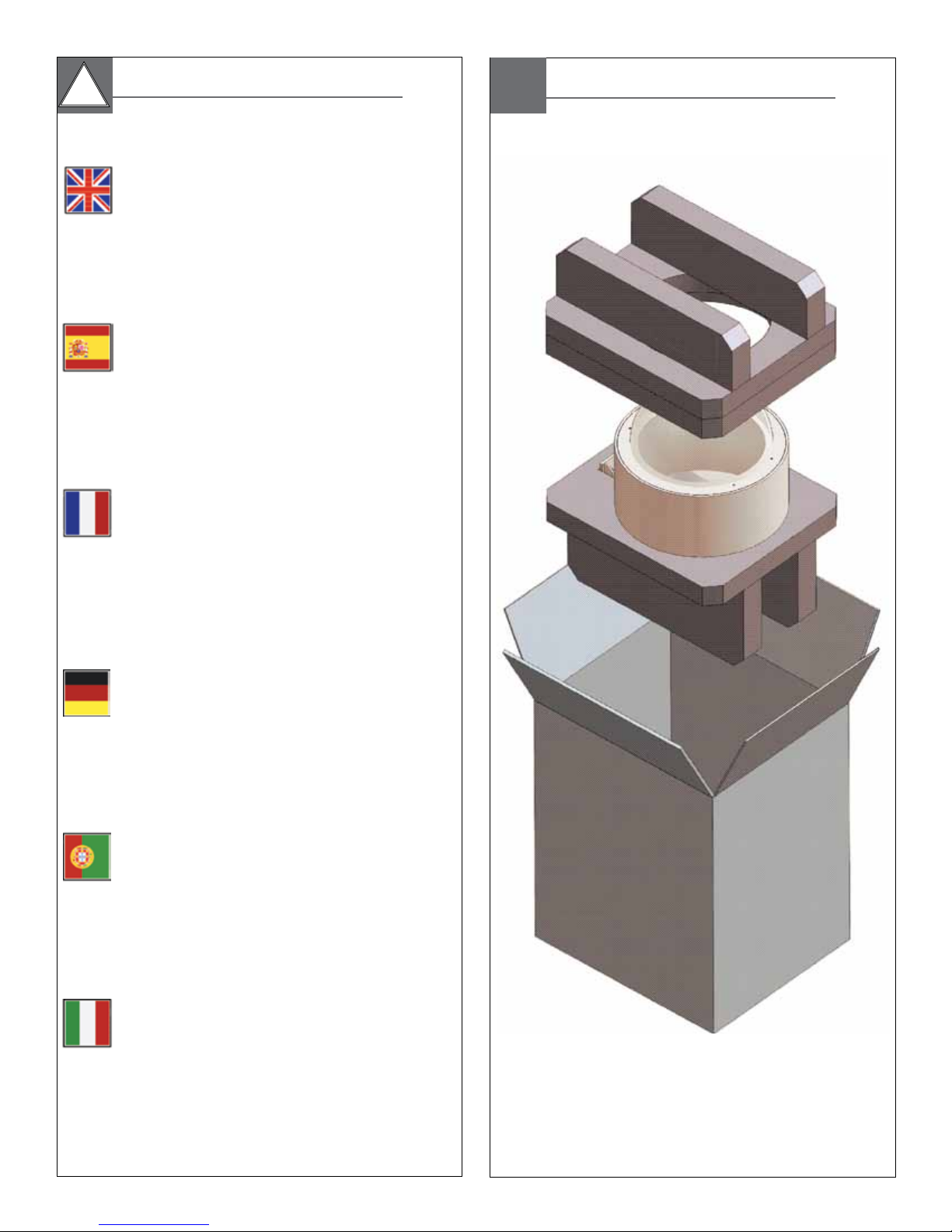
Content of Box
DDW10CR
PDDW10CR
Français
Deutsch
Portuguese
CARACTÉRISTIQUES D'APPAREIL-PHOTO
Résolution - 470 TVL - NTSC, 460TVL - pal
Illumination minimum - 1.0 1.0 lux
Rapport de bourdonnement - 26x, 3.5 -91mm optiques,
321x numérique
Format - ¼ »
Équilibre blanc - automobile
Obturateur électronique - 22 étapes.
DDW10CR1 (N) 115 VAC, 90 VA, 0.8 Amps
DDW10CR2 (N) 24 VAC, (Kategorie 2), 90 VA, 3.75Amps
KAMERA-SPEZIFIKATIONEN
Entschließung - 470 TVL - NTSC, 460TVL - PAL
Minimale Ablichtung - 1.0 1.0 Lux
Summen-Verhältnis - 26x, 3.5 -91mm optisch, 321x digital
Format - ¼“
Weiße Balance - Automobil
Elektronischer Blendenverschluß - 22 Schritte.
DDW10CR1 (N) 115 VAC, 90 vA, 0.8 ampères
DDW10CR2 (N) 24 VAC, (classe 2), 90 vA, 3.75Amps
ESPECIFICAÇÕES DA CÂMERA
Definição - 470 TVL - NTSC, 460TVL - PAL
Iluminação mínima - 1.0 1.0 Lux
Relação de zumbido - 26x, 3.5 -91mm óticos, 321x digital
Formato - ¼”
Contrapeso branco - automóvel
Obturador eletrônico - 22 etapas.
DDW10CR1 (N) 115 VCA, 90 vA, 0.8 ampèri
DDW10CR2 (N) 24 VCA, (codice categoria 2), 90 vA,
3.75Amps
SPECIFICHE DELLA MACCHINA FOTOGRAFICA
Italiano
Risoluzione - 470 TVL - NTSC, 460TVL - pal
Illuminazione minima - 1.0 1.0 lux
Rapporto di zoom - 26x, 3.5 -91mm ottici, 321x digitale
Disposizione - ¼„
Equilibrio bianco - automobile
Otturatore elettronico - 22 punti.
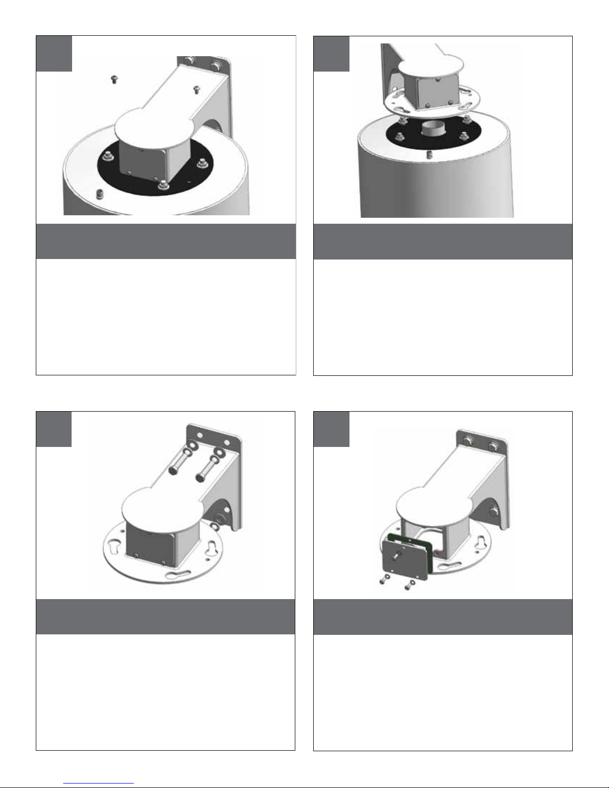
Remove (2) tamper resistant with the security tool
provided in the packet.
• Quite (2) a pisón resistente con la herramienta de la seguridad
proporcionada en el paquete.
• Enlevez (2) le bourreur résistant avec l'outil de sécurité fourni dans le
paquet.
• Entfernen Sie (2) den Besetzer, der mit dem Sicherheit Werkzeug
beständig ist, das im Paket bereitgestellt wird.
• Remova (2) a calcadeira resistente com a ferramenta da segurança
fornecida no pacote.
• Rimuova (2) il compressore resistente con l'attrezzo di sicurezza fornito
nel pacchetto.
Loosen all flange nuts and turn the housing clockwise to
remove the housing from the mount. The wall mount
can now be attached to the wall.
• Afloje todas las tuercas del reborde y dé vuelta a la cubierta a la derecha
para quitar la cubierta del montaje. El montaje de la pared se puede ahora
unir a la pared.
• Détachez tous les écrous de bride et tournez le logement dans le sens des
aiguilles d'une montre pour enlever le logement du bâti. Le bâti de mur peut
maintenant être fixé au mur.
• Lösen Sie alle Flanschnüsse und drehen Sie das Gehäuse nach rechts, um das
Gehäuse von der Einfassung zu entfernen. Die Wandeinfassung kann zur Wand
jetzt angebracht werden.
• Afrouxe todas as porcas da flange e gire a carcaça no sentido horário para
remover a carcaça da montagem. A montagem da parede pode agora ser
unida à parede.
• Allenti tutti i dadi della flangia e giri l'alloggiamento in senso orario per
rimuovere l'alloggiamento dal supporto. Il supporto della parete può ora essere
fissato alla parete.
1 2
Bolt Housing securely to wall or pole.
• Cubierta de perno con seguridad a la pared o al poste.
• Logement de boulon solidement au mur ou au poteau.
• Schraubbolzen-Gehäuse sicher zur Wand oder zum Pfosten.
• Carcaça de parafuso firmemente à parede ou ao pólo.
• Alloggiamento di bullone saldamente alla parete o al palo.
43
After the wall mount is securely attached to the wall,
remove the tamper resistant screws and take off the
access plate.
• Después de que el montaje de la pared se una con seguridad a la
pared, quite los tornillos resistentes del pisón y saque la placa del
acceso.
• Après que le bâti de mur soit solidement fixé au mur, enlevez les vis
résistantes de bourreur et enlevez le plat d'accès.
• Nachdem die Wandeinfassung sicher zur Wand angebracht ist,
entfernen Sie die beständigen Schrauben des Besetzers und entfernen
Sie die Zugang Platte.
• Depois que a montagem da parede é unida firmemente à parede,
remova os parafusos resistentes da calcadeira e retire a placa do
acesso.
• Dopo che il supporto della parete sia fissato saldamente alla parete,
rimuova le viti resistenti del compressore e tolga la piastra di accesso.
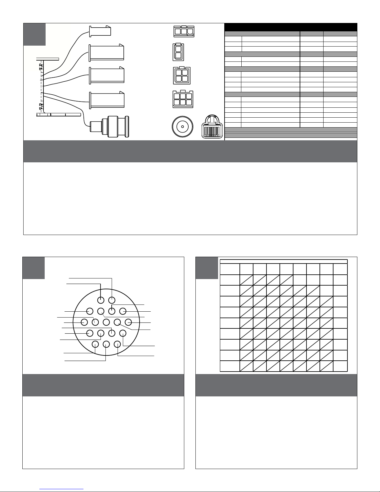
Wiring for DDW10CR
• Cableado para DDW10CR
• Câblage pour DDW10CR
• Verdrahtung für DDW10CR
• Fiação para DDW10CR
• Collegamenti per DDW10CR
2
1
4
3
1
2
321
654
A
B
C
D
E
1
23
Wiring Chart Non-Pressurized Receiver Version
A. Heater 24VAC 115VAC
1) Red - Heater 1
2) N/C 2.4A .5A
3) Red - Heater
B. Camera Power (58W) (58W)
1) Black - V2 1.5A .3A
2) Orange - V1
C. Lens ANALOG/ IP (36W) (36W)
1) Blue - Alarm Input 1
2) Violet - Alarm Input 2
3) Gray - Alarm Input 3
4) White - Alarm common
D. Pan/Tilt
1) Gray - RXA
2) Pink - N/C
3) Tan - TXA
4) Green - RXB
5) Brown - N/C
6) Blue - TXB
E. BNC 1(NETWORK IP)
F. Green Housing Ground (not shown)
or
5
6
6 7
Video
Shield
L
A
K
P
R
E F
MN
U T
S
J
H
G
TXA
TXB
NC
NC
RXA
B
C
D
RXB
Heater /Blower
Heater /Blower
Wiring for Pressurized Receiver model
(PDDW10CR2)
• Cableado para el modelo a presión del receptor (PDDW10CR2)
• Câblage pour le modèle pressurisé de récepteur (PDDW10CR2)
• Verdrahtung für unter Druck gesetztes Empfängermodell (PDDW10CR2)
• Fiação para o modelo pressurizado do receptor (PDDW10CR2)
• Collegamenti per il modello pressurizzato della ricevente (PDDW10CR2)
Alarm Common
Alarm In 2
Alarm In 3
Alarm In 1
NC
Camera Power
Camera Power
Wire Gauge
,75201,0181,5162,514412610MM
600
960
121
54.9
43.0
27.4
21.3
17.1
14.3
12.2
10.3
300
225
130
112
90
75
64
55
182
91.4
68.6
39.6
34.1
27.4
22.9
19.5
16.8
480
358
225
179
143
119
102
85
292
146
109
68.6
54.6
43.6
36.2
31.1
25.9
- - -
800
1300
243
396
571
905
174
275
350
525
106
160
285
452
86.9
138
228
362
69.5
110
190
301
57.9
91.7
163
258
49.7
78.6
140
215
42.7
65.5
1440
830
720
576
480
411
340
-
438
252
219
175
146
125
103
AWG
2
5.5
10
20
30
40
50
60
70
80
ft
120
86
65
44
35
29
25
31
,5
22
36.5
27.1
19.8
13.4
10.6
9.4
8.8
7.6
400
m
180
141
90
70
56
47
40
34
Total vA
consumed
These are recommended maximum distances
for 24VAC with a 10% voltage drop.
• Éstos se recomiendan las distancias máximas para
24VAC con una caída de voltaje del 10%.
• Ceux-ci sont recommandés des distances maximum
pour 24VAC avec une chute de tension de 10%.
• Diese werden maximale Abstände für 24VAC mit
einem 10% Spannungsabfall empfohlen.
• Estes são recomendados distâncias máximas para
24VAC com uma queda de tensão de 10%.
• Questi sono suggeriti distanze massime per 24VAC con
una differenza de potenziale di 10%.
 Loading...