

Moog Videolarm LDW75CLG Installation And Operation Instructions Manual
L I B E R T Y ™ S e r i e s
City-Wide Surveillance
Installation and Operation Instructions for the following models:
LDW75CLG Liberty Series wireless IP Ready dome. Include cellular
router, power supply for the complete system. Cellular
broadband adapter sold separately. 110/220VAC input.
Designed to work with Moog-Videolarm’s IP Ready Series
of IP camera housings.
Before attempting to connect or operate this product,
please read these instructions completely.
www.videolarm.com
CERTIFIED
81-IN5453
05-17-2010
IMPORTANT SAFEGUARDS SAFETY PRECAUTIONS
1 Read these instructions.
2 Keep these instructions.
3 Heed all warnings
4 Follow all instructions.
5 Do not use this apparatus near water.
6 Clean only with damp cloth.
7 Do not block any of the ventilation openings. Install in accordance with the
manufacturers instructions.
8 Cable Runs- All cable runs must be within permissible distance.
9 Mounting - This unit must be properly and securely mounted to a supporting
structure capable of sustaining the weight of the unit.
Accordingly:
a. The installation should be made by a qualified installer.
b. The installation should be in compliance with local codes.
c. Care should be exercised to select suitable hardware to install the unit, taking into
account both the composition of the mounting surface and the weight of the
unit.
10 Do not install near any heat sources such as radiators, heat registers, stoves, or other
apparatus ( including amplifiers) that produce heat.
11 Do not defeat the safety purpose of the polarized or grounding-type plug. A
polarized plug has two blades with one wider than the other. A grounding type
plug has two blades and a third grounding prong. The wide blade or the third
prong are provided for your safety. When the provided plug does not fit into your
outlet, consult an electrician for replacement of the obsolete outlet.
12 Protect the power cord from being walked on or pinched particularly at plugs,
convenience receptacles, and the point where they exit from the apparatus.
13 Only use attachment/ accessories specified by the manufacturer.
14 Use only with a cart, stand, tripod, bracket, or table specified by the manufacturer,
or sold with the apparatus. When a cart is used, use caution when moving the cart/
apparatus combination to avoid injury from tip-over.
15 Unplug this apparatus during lighting storms or when unused for long periods of time.
16 Refer all servicing to qualified service personnel. Servicing is required when the
apparatus has been damaged in any way, such as power-supply cord or plug is
damaged, liquid has been spilled of objects have fallen into the apparatus, the
apparatus has been exposed to rain or moisture, does not operate normally, or
has been dropped.
Be sure to periodically examine the unit and the supporting structure to make sure that the
integrity of the installation is intact. Failure to comply with the foregoing could result in the
unit separating from the support structure and falling, with resultant damages or injury to
anyone or anything struck by the falling unit.
UNPACKING
Unpack carefully. Electronic components can be
damaged if improperly handled or dropped. If an item
appears to have been damaged in shipment, replace
it properly in its carton and notify the shipper.
Be sure to save:
1 The shipping carton and packaging material.
They are the safest material in which to make
future shipments of the equipment.
2 These Installation and Operating Instructions.
SERVICE
If technical support or service is needed, contact us
at the following number:
CAUTION: TO REDUCE THE RISK OF
ELECTRIC SHOCK, DO NOT REMOVE
COVER ( OR BACK). NO USER- SERVICE-
ABLE PARTS INSIDE. REFER SEVICING TO
QUALIFIED SERVICE PERSONNEL.
The lightning flash with an arrowhead
symbol, within an equilateral triangle, is
intended to alert the user to the presence
of non-insulated “dangerous voltage”
within the product’s enclosure that may be
of sufficient magnitude to constitute a risk
to persons.
Este símbolo se piensa para alertar al usuario a la
presencia del “voltaje peligroso no-aisIado” dentro del
recinto de los productos que puede ser un riesgo de
choque eléctrico.
Ce symbole est prévu pour alerter I’utilisateur à la
presence “de la tension dangereuse” non-isolée dans la
clôture de produits qui peut être un risque de choc
électrique.
Dieses Symbol soll den Benutzer zum Vorhandensein der
nicht-lsolier “Gefährdungsspannung” innerhalb der
Produkteinschließung alarmieren die eine Gefahr des
elektrischen Schlages sein kann.
Este símbolo é pretendido alertar o usuário à presença
“di tensão perigosa non-isolada” dentro do cerco dos
produtos que pode ser um risco de choque elétrico.
Questo simbolo è inteso per avvertire I’utente alla
presenza “di tensione pericolosa” non-isolata all’interno
della recinzione dei prodotti che può essere un rischio di
scossa elettrica
The exclamation point within an equilateral
triangle is intended to alert the user to
presence of important operating and
maintenance (servicing) instructions in the
literature accompanying the appliance.
Este símbolo del punto del exclamation se piensa para
alertar al usuario a la presencia de instrucciones
importantes en la literatura que acompaña la
aplicación.
Ce symbole de point d’exclamation est prévu pour
alerter l’utilisateur à la presence des instructions
importantes dans la littérature accompagnant
l’appareil.
Dieses Ausruf Punktsymbol soll den Benutzer zum
Vorhandensein de wichtigen Anweisungen in der
Literatur alarmieren, die das Gerät begleitet.
Este símbolo do ponto do exclamation é pretendido
alertar o usuário à presença de instruções importantes
na literatura que acompanha o dispositivo.
Questo simbolo del punto del exclamaton è inteso per
avvertire l’utente alla presenza delle istruzioni importanti
nella letteratura che accompagna l'apparecchio.
CAUTION
RISK OF ELECTRIC SHOCK
DO NOT OPEN
.
TECHNICAL SUPPORT
AVAILABLE 24 HOURS
1- 800 - 554 -1124

LIMITED WARRANTY
FOR VIDEOLARM INC. PRODUCTS
VIDEOLARM INC. warrants this Product to be free from defectsin material or workmanship,asfollows:
PRODUCTCATEGORY PARTS LABOR
All Enclosures and Electronics Five (5) Years Five (5) Years
Pan/Tilts Three (3) Years **6 months if used in autoscan Three (3) Years **6 months if used in autoscan
Poles/PoleEvators Three (3) Years Three (3) Years
Warrior/Q-View/I.R. Illuminators Five (5) Years Five (5) Years
Controllers Five (5) Years Five (5) Years
Power Supplies Five (5) Years Five (5) Years
Accessory Brackets Five (5) Years Five (5) Years
During the labor warranty period, to repair the Product, Purchaser will either return the defective product, freight prepaid, or deliver it to Videolarm Inc.
Decatur GA. The Product to be repaired is to be returned in either its original carton or a similar package
an equal degree of protection with a
RMA # (Return Materials Authorization number) displayed on the outer box or packing slip. To obtain a RMA# you must contact our Technical Support
Team at 800.554.1124, extension 101.Videolarm will return the repaired Product freight prepaid to Purchaser. Videolarm is not obligated to provide
Purchaser with a substitute unit during the warranty period or at any time. After the applicable warranty period, Purchaser must pay all labor and/or
parts charges.
1.NOTIFICATIONOFCLAIMS: WARRANTYSERVICE:If Purchaser believes that the Product is defective in material or workmanship, then written notice
with an explanation of the claim shall be given promptly by Purchaser toVideolarm but all claims for warranty service must be made within the
warranty period. If after investigation Videolarm determines that the reported problem was not covered by the warranty, P
urchaser shall pay Videolarm
for the cost of investigating the problem at its then prevailing per incident billable rate. No repair or replacement of any Product or part thereof shall
extend the warranty period as to the entire Product. The
warranty on the repaired part only shall be in for a period of ninety (90) days
following the repair or replacement of that part or the remaining period of the Product parts warranty, whichever is greater.
2.EXCLUSIVE REMEDY: ACCEPTANCE:Purchaser’s exclusive remedy and Videolarm’s sole obligation is to supply (or pay for) all labor necessary to repair
any Product found to be defective within the warranty period and to supply, at no extra charge, new or rebuilt replacements for defective parts.
3.EXCEPTIONS TO LIMITED WARRANTY: Videolarm shall have no liability or obligation to Purchaser with respect to any Product requiring service
during the warranty period which is subjected to any of the following: abuse, improper use: negligence, accident, lightning damage or other acts
of God (i.e., hurricanes, earthquakes),
failure of the end-user to follow the directions outlined in the product instructions, failure of the
end-user to follow the maintenance procedures recommended by the International Security Industry Organization, written in product instructions,
or recommended in the service manual for the Product. Furthermore, Videolarm shall have no liability where a schedule is
for regular
replacement or maintenance or cleaning of certain parts (based on usage) and the end-user has failed to follow such schedule; attempted repair by
personnel; operation of the Product outside of the published environmental and electrical parameters, or if such Product’s original
(trademark, serial number) markings have been defaced, altered, or removed. Videolarm excludes from warranty coverage Products sold
AS IS and/or WITH ALL FAULTS and excludes used Products which have not been sold by Videolarm to the Purchaser. All software and accompanying
documentation furnished with, or as part of the Product is furnished “AS IS” (i.e., without any warranty of any kind), except where expressly provided
otherwise in any documentation or license agreement furnished with the Product.
4.PROOF OF PURCHASE:The Purchaser’s dated bill of sale must be retained as evidence of the date of purchase and to establish warranty eligibility.
DISCLAIMEROF WARRANTY
EXCEPT FOR THE FOREGOINGWARRANTIES, VIDEOLARM HEREBY DISCLAIMS AND EXCLUDES ALL OTHER WARRANTIES, EXPRESS OR IMPLIED,
INCLUDING, BUT NOT LIMITEDTO ANY AND/OR ALL IMPLIED WARRANTIES OF MERCHANTABILITY, FITNESS FOR A PARTICULAR PURPOSE AND/OR ANY WARRANTY WITH
REGARD TO ANY CLAIM OF INFRINGEMENTTHAT MAY BE PROVIDED IN SECTION 2-312(3) OF
THE UNIFORM COMMERCIAL CODE AND/OR IN ANY OTHER COMPARABLE
STATE STATUTE. VIDEOLARM HEREBY DISCLAIMS ANY REPRESENTATIONS OR WARRANTY THAT THE PRODUCT IS COMPATIBLE WITH ANY COMBINATION OF NON-VIDEOLARM
PRODUCTS OR NON-VIDEOLARM RECOMMENDED PRODUCTS PURCHASER CHOOSES TO CONNECT TO PRODUCT.
LIMITATION OF LIABILITY
THE LIABILITY OF VIDEOLARM, IF ANY, AND PURCHASER’S SOLE AND EXCLUSIVE REMEDY FOR DAMAGES FOR ANY CLAIM OF ANY KIND
WHATSOEVER, REGARDLESS OFTHE LEGAL THEORY AND WHETHER ARISING INTORT OR CONTRACT, SHALL NOT BE GREATERTHAN THE ACTUAL PURCHASE PRICE OF THE
PRODUCT WITH RESPECT TO WHICH SUCH CLAIM IS MADE. IN NO EVENT SHALL VIDEOLARM BE LIABLE TO PURCHASER FOR ANY SPECIAL, INDIRECT, INCIDENTAL, OR
CONSEQUENTIAL DAMAGES OF ANY KIND INCLUDING, BUT NOT LIMITED TO, COMPENSATION, REIMBURSEMENT OR DAMAGES ON ACCOUNT OF THE LOSS OF PRESENT
OR PROSPECTIVE PROFITS OR FOR ANY OTHER REASON WHATSOEVER.
/tour operation
/tour operation
**6 months if used in autoscan
/tour operation
**6 months if used in autoscan
/tour operation
SView Series Five (5) Years
Five (5) Years
The limited warranty stated in these product instructions is subject to all of the following terms and conditions:
TERMS AND CONDITIONS
Electrical Specifications
!!
120/240 VAC 50/60Hrz.
Accessories: Heater: 50 Watts, Blower: 2 Watt
Camera Power: (See Camera Specifications): 40 Watts Max
English
120/240VAC 50/60Hrz.
96 Vatios
De Accesorios: Calentador: 50 Watts, Blower: 2 Vatio
Energía De la Cámara fotográfica De : (Véase Las
Especificaciones De la Cámara fotográfica): 40 Vatios
De Herramientas Máximas
Español
120/240VCA 50/60Hrz.
96 Watts
D'Accessoires : Réchauffeur : 50 Watts, Ventilateur : 2 watts.
Puissance D'Appareil-photo : (Voir Les Caractéristiques
D'Appareil-photo) : 40 Watts De Maximum
Français
120/240VAC 50/60Hrz.
96 Watt
Zusatzgerät-: Heizung: 50 Watts, Blower: 2
Watt-Kamera-Energie: (Sehen Sie Kamera-Spezifikationen):
40 Watt Maximale
Deutsch
120/240VAC 50/60Hrz.
96 Watts
De Acessórios: Calefator: 50 Watts, Blower: 2 Watt
Poder Da Câmera De : (Veja Especificações Da Câmera):
40 Watts De Ferramentas Máximas
Portuguese
120/240VCA 50/60Hrz.
96 Watt
Di Accessori: Riscaldatore: 50 Watts, Blower: 2 Watt
Alimentazione Della Macchina fotografica Da :
(Veda Le Specifiche Della Macchina fotografica): 40 Watt
Di Attrezzi Massimi
Italiano
96 Watts
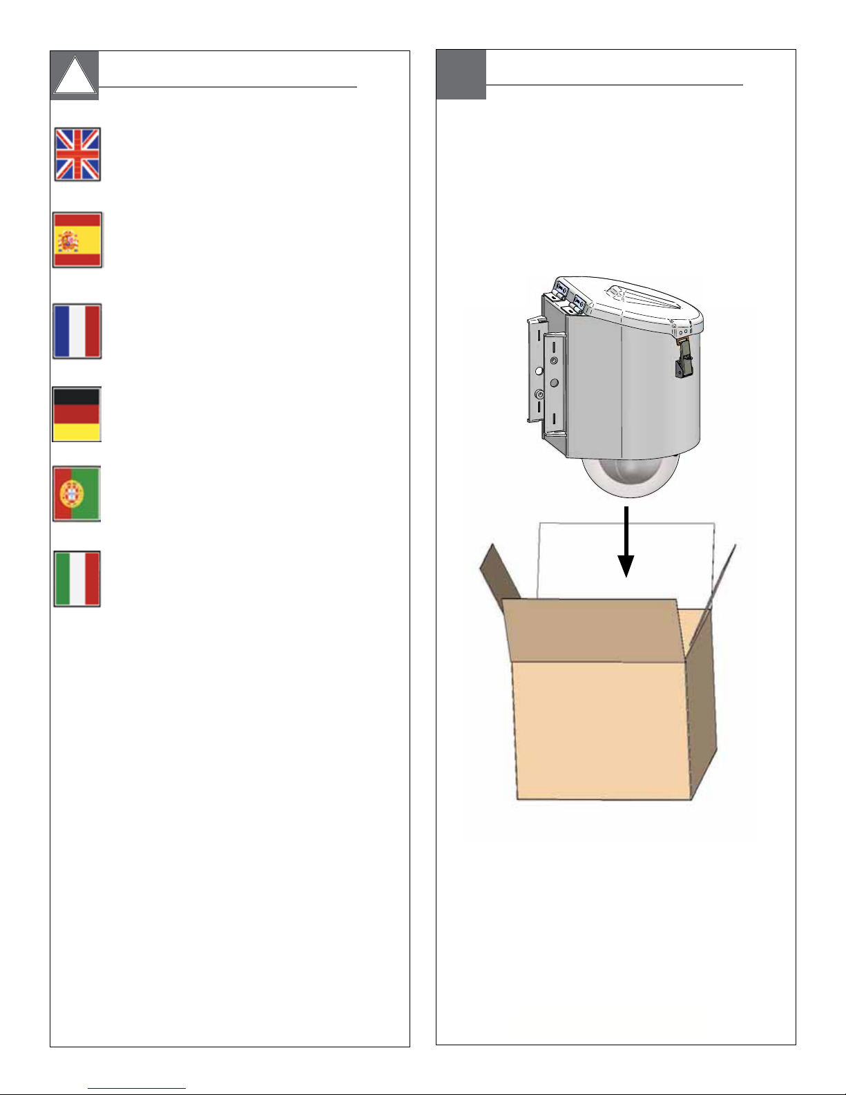
LDW75CLG
Content of Box
Power Feed Locations:
LIQUID TIGHT PLUG FOR
3G ANTENNA BULKHEAD
CONNECTOR HOLE.
LIQUID TIGHT PLUG FOR
OPTIONAL MAIN
POWER HOLE.
LIQUID TIGHT PLUG FOR
OPTIONAL MAIN
POWER HOLE.
LIQUID TIGHT
STRAIN RELIEF
FOR MAIN POWER HOLE.

Attach the housing onto the bracket secure by
using the provided 2 (M10) bolts and washers.
• Ate la cubierta sobre el soporte seguro usando los 2 pernos
(M10) y arandelas proporcionados.
• Attachez le logement sur la parenthèse bloquée en employ-
ant les 2 boulons (M10) et rondelles fournis.
• Bringen Sie das Gehäuse auf den Haltewinkel an, der indem
Sie die zur Verfügung gestellten 2 sicher ist, Schraubbolzen
(M10) und die Unterlegscheiben verwenden.
• Una a carcaça no suporte seguro usando os 2 parafusos
(M10) e arruelas fornecidos.
• Attacchi l'alloggiamento sulla staffa sicura usando i 2 bulloni
(M10) e rondelle forniti.
POLE MOUNTING
1 2
Holes for
steel straps
LDW75CLG unit is ready to mount. Use marked
holes to attach steel straps.
• La unidad de LDW75CLG está lista para montar. Utilice
los agujeros marcados para atar las correas de acero.
• L'unité de LDW75CLG est prête à monter. Employez les
trous marqués pour attacher les courroies en acier.
• LDW75CLG Maßeinheit ist bereit anzubringen. Benutzen
Sie markierte Löcher, um Stahlbügel anzubringen.
• A unidade de LDW75CLG está pronta para montar.
Use furos marcados para unir as cintas de aço.
• L'unità di LDW75CLG è pronta a montare. Usi i profondi
fori per attaccare le cinghie d'acciaio.
3
Use the steel straps to mount the unit to pole.
• Utilice las correas de acero para montar la unidad al
poste.
• Employez les courroies en acier pour monter l'unité au
poteau.
• Benutzen Sie die Stahlbügel, um die Maßeinheit zum
Pfosten anzubringen.
• Use as cintas de aço para montar a unidade ao pólo.
• Usi le cinghie d'acciaio per montare l'unità al palo.
4
Attach pole clips to bracket as shown. Use hardware
provided. For easy removal additional mounting options.
• Ate los clips del poste para acorchetar como se muestra. Utilice el hardware
proporcionado. Para las opciones adicionales del montaje del retiro fácil.
• Attachez les agrafes de poteau à la parenthèse comme montrée. Utilisez le
matériel fourni. Pour des options additionnelles de support de déplacement
facile.
• Bringen Sie Pfostenclips an, um wie gezeigt einzuklammern. Benutzen Sie die
bereitgestellte Hardware. Für zusätzliche Montagewahlen des einfachen
Abbaus.
• Una grampos do pólo ao suporte como mostrado. Use a ferragem
fornecida. Para opções adicionais da montagem da remoção fácil.
• Attacchi le clip del palo alla staffa come indicata. Utilizzi i fissaggi forniti. Per
le opzioni supplementari del montaggio di rimozione facile.
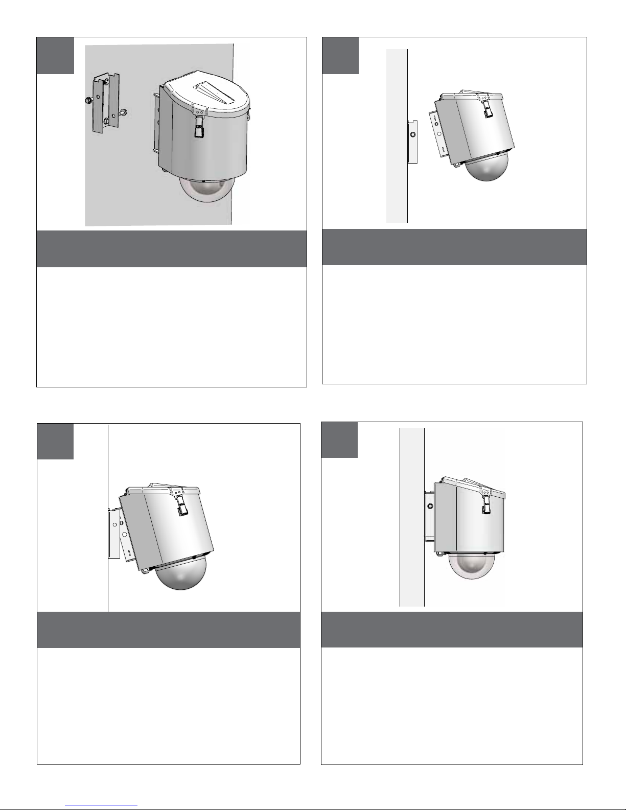
Wall mount option.
• Opción del montaje de la pared.
• Option de bâti de mur.
• Wandeinfassungswahl.
• Opção da montagem da parede.
• Opzione del supporto della parete.
Slide the tilted unit over the lips to lock it into
place.
• Deslice la unidad inclinada sobre los labios para
trabarla en lugar.
• Glissez l'unité inclinée au-dessus des lèvres pour la
fermer à clef sur l'endroit.
• Schieben Sie die gekippte Maßeinheit über den Lippen,
um sie in Platz zu verriegeln.
• Deslize a unidade inclinada sobre os bordos para
travá-la no lugar.
• Faccia scorrere l'unità inclinata sopra le labbra per
chiuderlo a chiave nel posto.
WALL MOUNTING
5
6
Tilt the unit to align the grooves (holes) to the
lips on the bracket.
• Incline la unidad para alinear los surcos (agujeros) con
los labios en el soporte.
• Inclinez l'unité pour aligner les cannelures (trous) sur les
lèvres sur la parenthèse.
• Kippen Sie die Maßeinheit, um die Nuten (Löcher) mit
den Lippen am Haltewinkel auszurichten.
• Incline a unidade para alinhar os sulcos (furos) aos
bordos no suporte.
• Inclini l'unità per allineare le scanalature (fori) alle
labbra sulla staffa.
7
8
Shows the wall mount option of hanging unit
and were to secure the bolt.
• Demuestra la opción del montaje de la pared de la
unidad colgante y eran asegurar el perno.
• Montre l'option de bâti de mur de l'unité accrochante
et était de fixer le boulon
• Zeigt die Wandeinfassungswahl der hängenden
Maßeinheit und war, den Schraubbolzen zu sichern.
• Mostra a opção da montagem da parede da unidade
de suspensão e eram fixar o parafuso.
• Mostra l'opzione del supporto della parete dell'unità
d'attaccatura ed erano di assicurare il bullone.
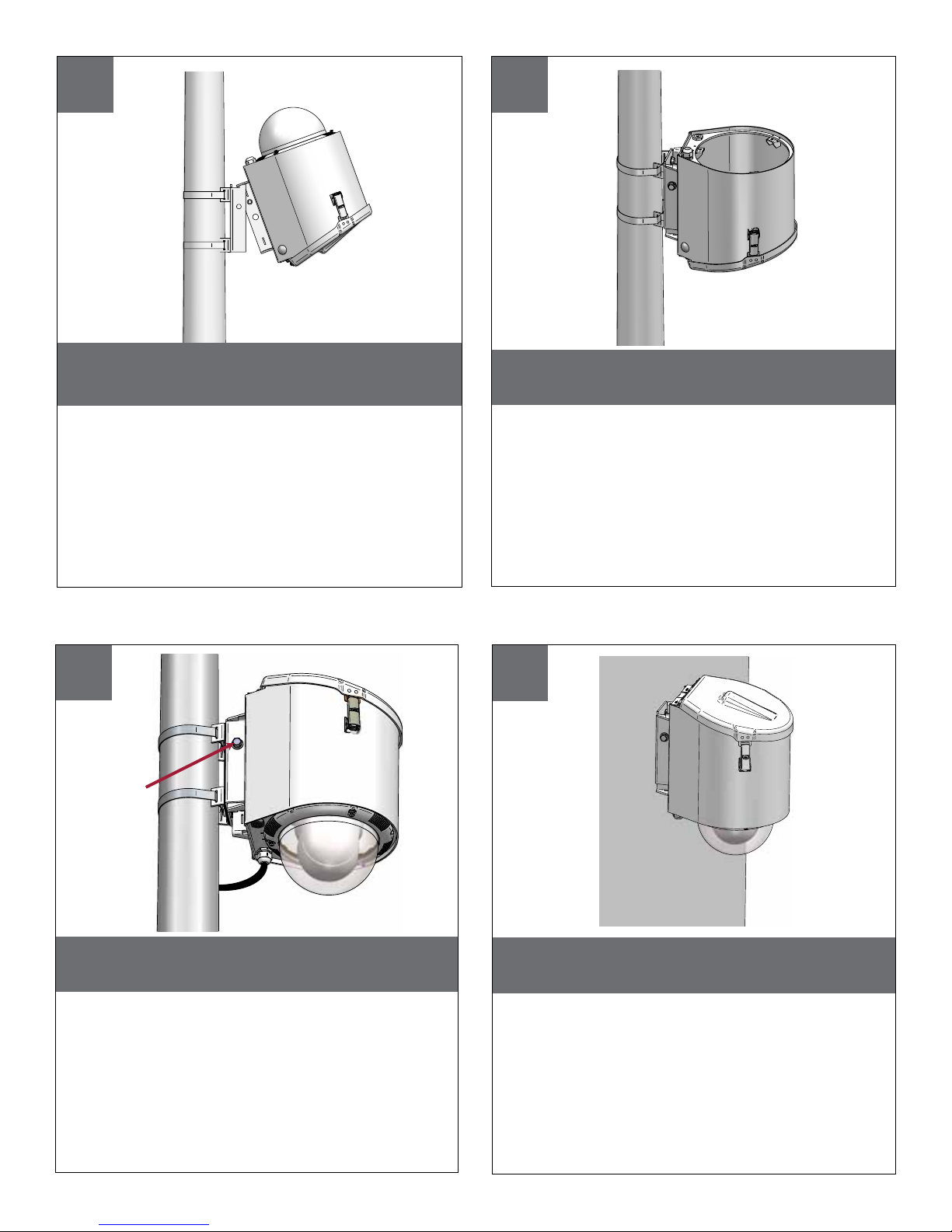
9
10
To assemble a camera or for the maintenance of the
unit (if needed) you should flip so that the dome is
facing upwards.
• Para montar una cámara o para el mantenimiento de la unidad (si es
necesario) que usted debe mover de un tirón de modo que la bóveda esté
haciendo frente hacia arriba.
• Pour assembler un appareil-photo ou pour l'entretien de l'unité (si nécessaire)
que vous devriez renverser de sorte que le dôme fasse face vers le haut.
• Zu eine Kamera oder für die Wartung der Maßeinheit zusammenbauen
(wenn erforderlich), das Sie leicht schlagen sollten, damit die Haube
aufwärts gegenüberstellt.
• Para montar uma câmera ou para a manutenção da unidade (se
necessário) que você deve lanç de modo que a abóbada esteja
enfrentando para cima.
• Per per montare una macchina fotografica o per il mantenimento dell'unità
(se necessario) che dovreste lanciare in modo che la cupola stia
affrontando verso l'alto.
11
Bolts /washers
Remove the dome and follow the specified
camera mounting options.
• Quite la bóveda y siga las opciones especificadas del
montaje de la cámara.
• Enlevez le dôme et suivez les options spécifiques de
support d'appareil-photo.
• Entfernen Sie die Haube und folgen Sie den spezifizierten Kameramontagewahlen.
• Remova a abóbada e siga as opções especific da
montagem da câmera.
• Rimuova la cupola e segua le opzioni specificate del
montaggio della macchina fotografica.
12
Complete the necessary electrical wiring. Use the provided
bolts and washers to secure the housing in place.
• Termine el cableado eléctrico necesario. Utilice los pernos y las
arandelas proporcionados para asegurar la cubierta en el lugar.
• Accomplissez le câblage électrique nécessaire. Employez les boulons
et les rondelles fournis pour fixer le logement en place.
• Schließen Sie die notwendige elektrische Verdrahtung ab. Benutzen Sie
die zur Verfügung gestellten Schraubbolzen und die Unterlegscheiben,
um das Gehäuse an der richtigen Stelle zu sichern.
• Termine a fiação elétrica necessária. Use os parafusos e as arruelas
fornecidos para fixar a carcaça no lugar.
• Completi i collegamenti elettrici necessari. Usi i bulloni e le rondelle
forniti per fissare l'alloggiamento sul posto.
Shows the unit mounted to the wall.
• Demuestra la unidad montada a la pared.
• Montre l'unité montée au mur.
• Zeigt die Maßeinheit, die zur Wand angebracht wird.
• Mostra a unidade montada à parede.
• Mostra l'unità montata alla parete.
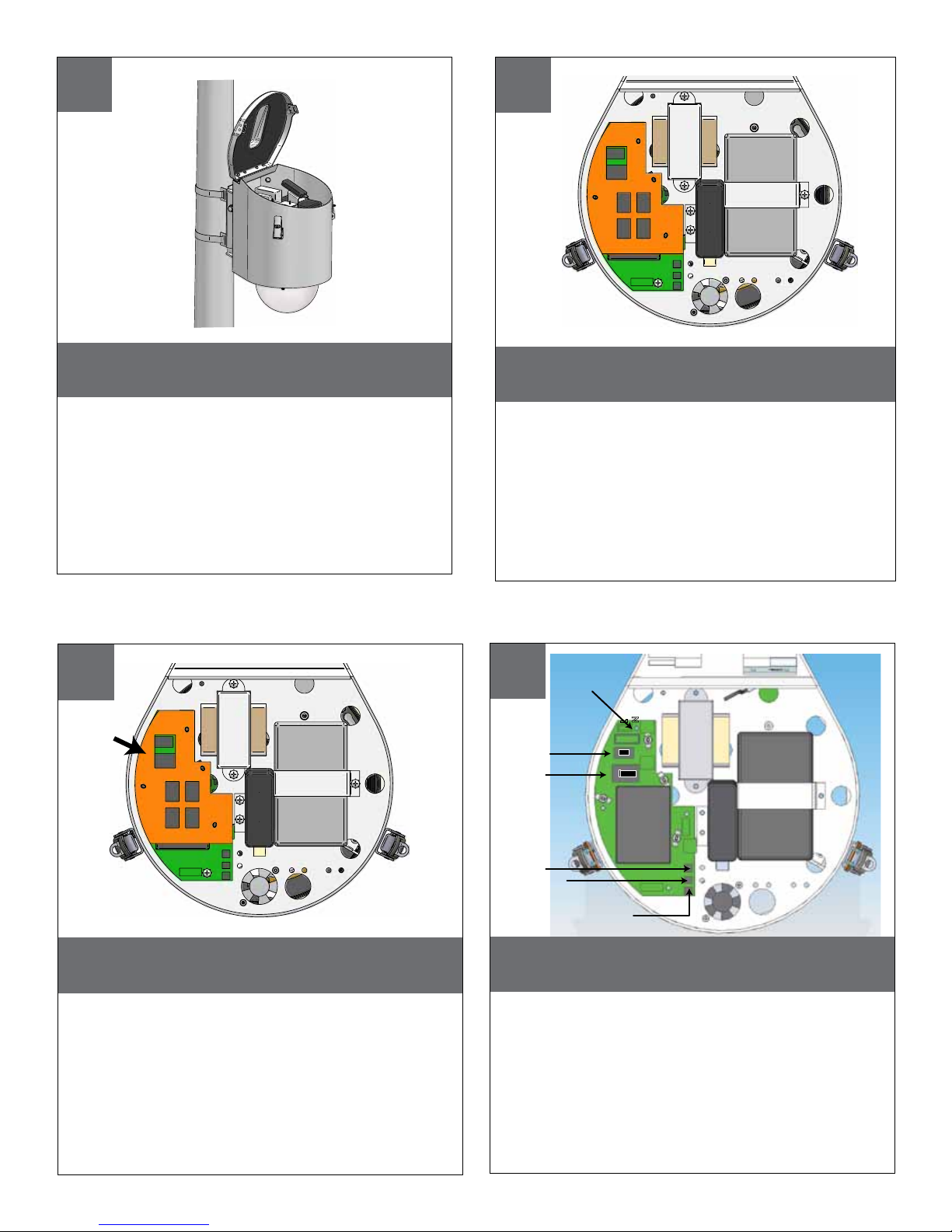
13
14
To open the top cover unlock the latches.
From here you can activate the unit
• Para abrir la cubierta superior abra los cierres. Aquí de usted
puede activar la unidad.
• Pour ouvrir la couverture supérieure ouvrez les verrous. D'ici
vous pouvez activer l'unité.
• Um die obere Abdeckung zu öffnen entriegeln Sie die
Verriegelungen. Von hier Ihnen kann die Maßeinheit aktivieren.
• Para abrir a tampa superior destrave as travas. Aqui de você
pode ativar a unidade.
• Per aprire la copertura superiore sblocchi i fermi. Di qui potete
attivare l'unità.
15
Remove
barrier
cover
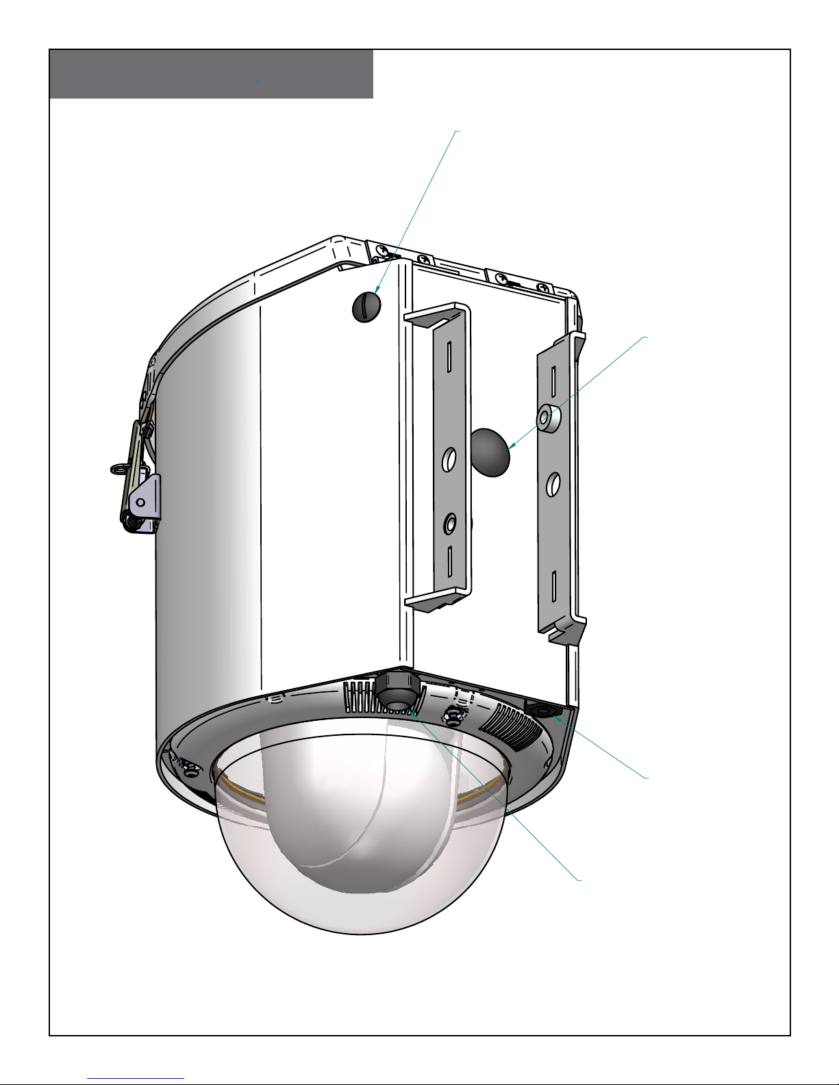
Top inside view of the unit.
• Tapa dentro de la vista de la unidad.
• Dessus à l'intérieur de la vue de l'unité.
• Oberseite innerhalb der Ansicht der Maßeinheit.
• Parte superior dentro da ideia da unidade.
• Parte superiore all'interno della vista dell'unità.
16
ON/OFF
switch (will
not turn off
wireless circuit)
115/240VAC
selector switch
120/240VAC
input
L
N
ON
OFF
120
220
Remove barrier cover.
• Quite la cubierta de la barrera.
• Enlevez la couverture de barrière.
• Entfernen Sie Sperrenabdeckung.
• Remova a tampa da barreira.
• Rimuova la copertura della barriera.
120/240VAC
Aux. output
24VAC
Aux. output
5VDC output
1. Move the 115//240VAC selector switch (3) to the desired position
2. Insure that the ON/OFF switch (2) is in the off position
3. Attach the in coming “main” power to the 120/240 VAC input
4. Move the ON/OFF switch (2) to the ON position.
• 1. Mueva el interruptor de selector 115//240VAC (3) a la posición deseada 2. Asegure que el
interruptor CON./DESC. (2) está en la posición de reposo 3. Ate en energía “principal” que viene a
la entrada de 120/240 VAC 4. Mueva el interruptor CON./DESC. (2) a la posición de trabajo.
• 1. Déplacez le sélecteur 115//240VAC (3) à la position désirée 2. Assurez-vous que le commutateur
"MARCHE/ARRÊT" (2) est dans la position de repos 3. Attachez dans la prochaine puissance «
principale » à l'entrée de 120/240 VCA 4. Déplacez le commutateur "MARCHE/ARRÊT" (2) à la
position de fonctionnement.
• 1. Verschieben Sie den Schalter des Wähl 115//240VAC (3) auf die gewünschte Position 2.
Versichern Sie, dass der Ein/Aus-Schalter (2) in der Ausschaltstellung ist 3. Bringen Sie in kommender
„Haupt“ Energie zum 120/240 VAC-Eingang an 4. Verschieben Sie den Ein/Aus-Schalter (2) auf die
Arbeitsstellung.
• 1. Mova o interruptor de seletor 115//240VAC (3) para a posição desejada 2. Segure que o
interruptor DE LIGAR/DESLIGAR (2) está no posição de repouso 3. Una no poder “principal” de
vinda à entrada de 120/240 de VAC 4. Mova o interruptor DE LIGAR/DESLIGAR (2) para o posição
de functionamento.
• 1. Sposti l'interruttore di selettore 115//240VAC (3) alla posizione voluta 2. Assicuri che l'interruttore
acceso/spento (2) è nella posizione di riposo 3. Attacchi nel potere “principale„ venente all'input
da 120/240 di VCA 4. Sposti l'interruttore acceso/spento (2) alla posizione di funzionamento.
 Loading...