

Moog Videolarm JK-PHO, JK-PHI Product Instructions
Manufactured by:
Before attempting to connect or operate this product, please read these instructions completely.
81-IN4500
6/17/02
for
IN-4500
MODELS: Outdoor Dome Housings
JK-PHO, JK-PHI
ELECTRICAL SPECIFICATIONS (OUTDOOR ONLY):
Power 24VAC, Class 2 Only
!
26 watts at 24 VAC (accessories)
Heater: 25 watts
Blower: .84 watts
Input Connectors (outdoor units):
BNC
(2) screw-down connectors
GENERAL INSTRUCTIONS:
Tools Required: .100" Flat Head Screwdriver
Phillips Head Screwdriver
1. Carefully remove the housing from the packaging material.
Check to be sure all parts are present.
2. This unit includes a 1 1/2" NPT housing coupling that can be
used with a standard 1 1/2" NPT pipe. The unit can be
used with other brackets designed with 1 1/2" male pipe
threads, such as the Toshiba's JK-WM and JK-PJM wall
mount brackets.
PRODUCT INSTRUCTIONS
INSTALLING QUICK RELEASE BRACKET AND PAN/TILT
CAMERA ASSEMBLY
NOTE: These installations should be completed before
mounting the housing.
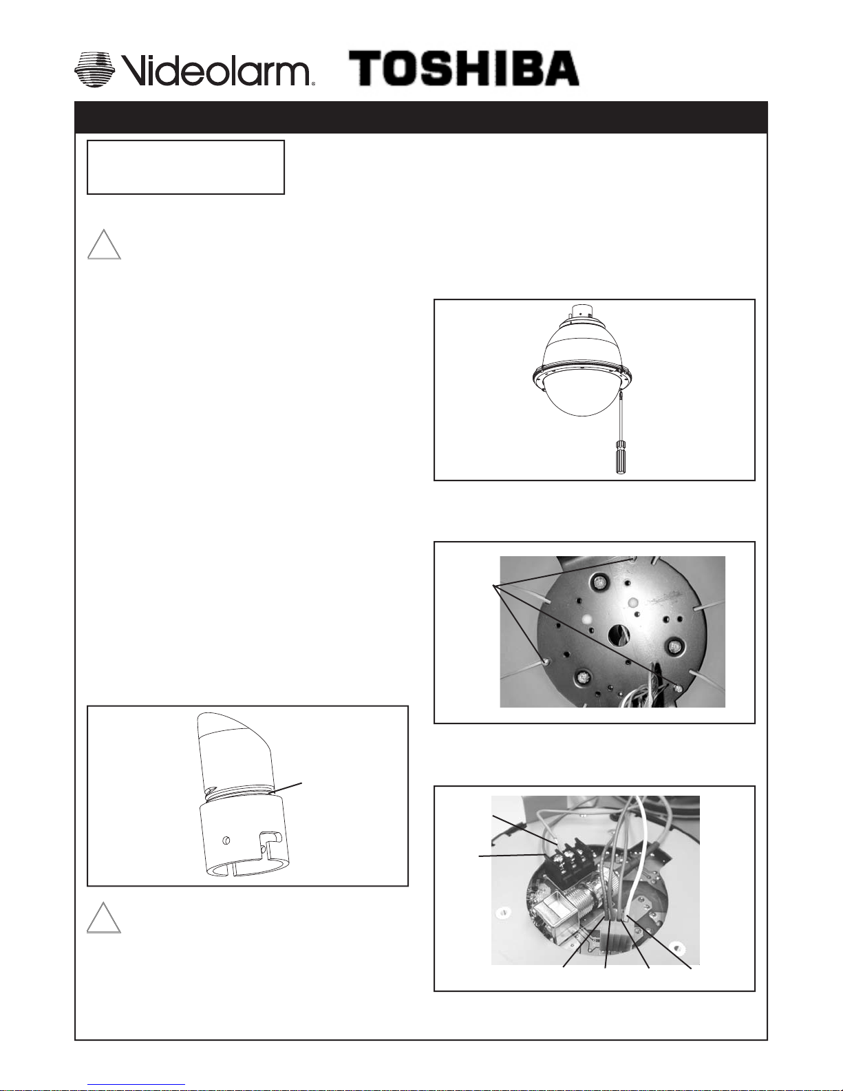
1. Open the housing by loosening the (3) captive screws located
on the housing ring next to the lower clear dome. Be careful
not to back these all the way out. Twist the dome slightly in a
counterclockwise motion to remove (Figure 2).
Loosen screws only,
do not remove
Remove dome by
twisting coun ter clock wise
Figure 2
2. Install the pan/tilt unit quick- release bracket using the three
6-32 Phillips head screws provided (Figure 3). Screw down
only about halfway.
Mounting
screws
3. Attach the housing coupling to the bracket or pendant pipe
(Figure 1).
NOTE: Pipe threads should be clean and rust free. Use a
sealer (such as Tefl on™ tape or silicone sealer) on the
threads.
Add thread
sealing tape
Figure 1
Be sure the bracket is properly and securely mounted
to a supporting structure capable of rigidly holding the
!
weight of the entire unit.
Figure 2
3. Make wiring connects from the housing to the Pan/Tilt base
(Figure 3). Use the Color Code Chart B on the next page for
correct connections.
Orange
Red
Figure 3
Blue Violet
Gray
White
A. Wiring Color Code
Power and Control Inputs
(Outside of housing)
POWER
1 Camera Power (24 VAC) Red
2 Camera Power (24 VAC) Orange
3 Accessory Power (24 VAC) Yellow
4 Accessory Power (24 VAC) Green
CONTROL
1 RS-485RXA Blue
2 RS-485RXB Violet
3 RS-485TXA Gray
4 RS-485TXB White
B. Power and Control Outputs
(Inside of housing)
POWER AND CONTROL LEADS
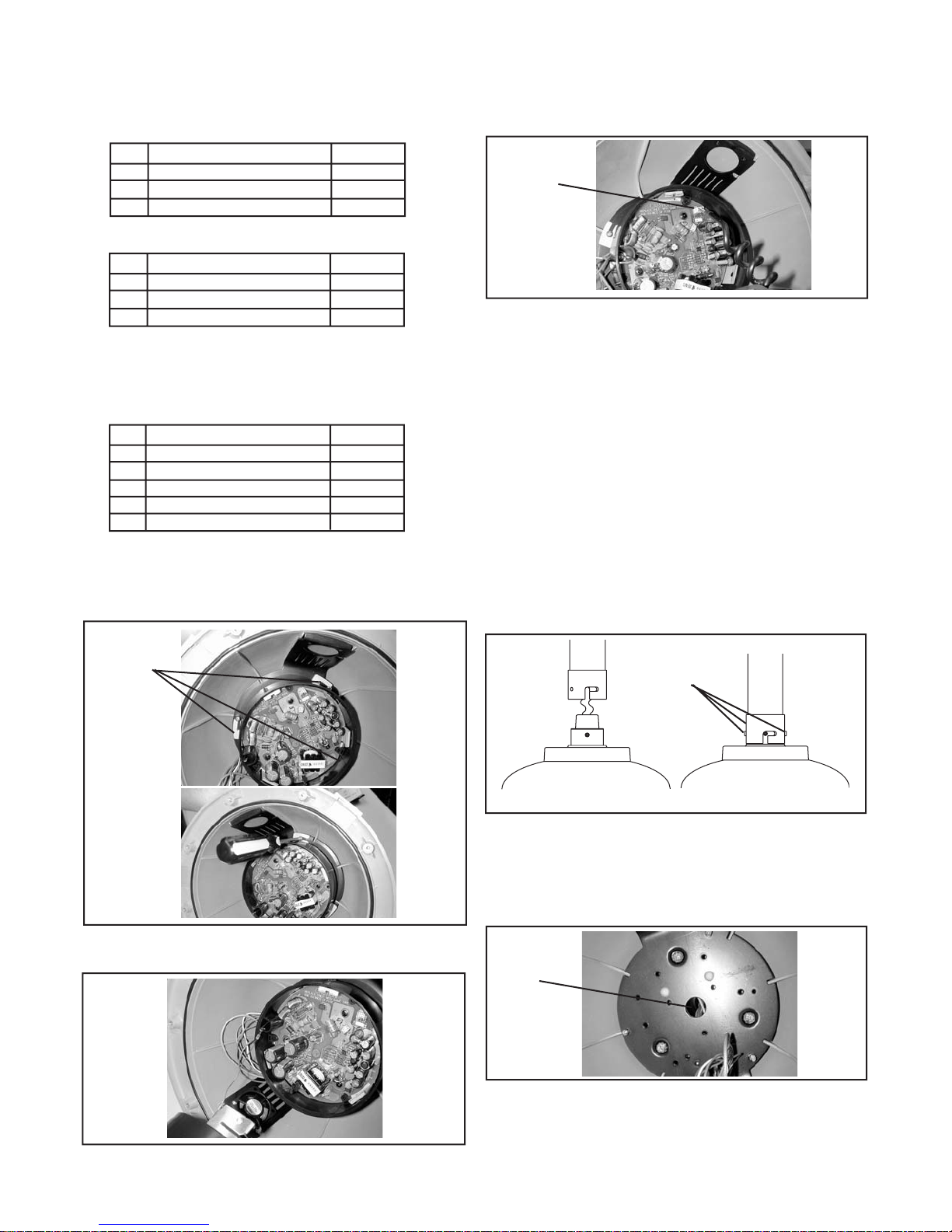
6. Attach the Six Position Pan/Tilt Connector from the camera to the
Pan/Tilt base (Figure 6). Connect the dome camera to the Pan/Tilt
base by aligning the notch on the Pan/Tilt base with the arrow on
the camera, and turning the camera clockwise until it locks.
Six Position
Pan/Tilt
Connector
Figure 6
7. Clean the inside of the dome with the text-wipe provided. Reat-
tach the housing dome and secure the (3) captive screws. DO
NOT OVERTIGHTEN THE SCREWS. Tighten only to the point at
which the gap between the ring and the housing top closes.
MOUNTING THE HOUSING
1 Camera Power (24 VAC) Red
2 Camera Power (24 VAC) Orange
3 RS-485RXA Blue
4 RS-485RXB Violet
5 RS-485TXA Gray
6 RS-485TXB White
4. Connect the Pan/Tilt base to the quick-release bracket by sliding
the slots on the top of the base over the screws on the quick-
release bracket. Tighten the screws to secure the base to the
bracket (Figure 4).
Place slots
over screws
in quickrelease
bracket
1. Mount the housing assembly to the mounting bracket and
housing coupling. A safety cable is included with the housing to
temporarily hold it while making wiring connections. Loop the
safety cable over one of the set screws on the housing coupling
2. Make the appropriate connections using the (2) screw-down
connectors supplied. Refer to Chart A as a guide.
3. Undo the safety cable and twist the housing onto the housing
coupling. Secure all (3) set screws provided on the housing
coupling (Figure 7).
Twist and
Secure
Figure 6
4. Clean the outside of the dome with the text wipe provided.
WIRING FOR INDOOR UNITS
Figure 4
5. Attach the safety cable on the bottom of the camera onto the slot
on the Pan/Tilt base (Figure 5).
Figure 5
1. Run incoming wiring into the top of the housing and through the
hole in the center of the quick release bracket. (Figure 7).
Center
hole
Figure 7
2. Attach the housing to the pendant coupling.
3. Connect the wiring to the Pan/Tilt base per Toshiba's instructions.
- 2 -
 Loading...