

Moog Videolarm IP Ready RHW75C2N, IP Ready RHP75C2N Product Instructions
Product
Instructions
IP Ready™ Rugged Housing Series
RHW75C2N & RHP75C2N
Before attempting to connect or operate this product,
please read these instructions completely.
81-IN5309
04/21/06
- 1 -
!
!
1. Read Instructions - All the safety and operating instructions
should be read before the unit is operated.
2. Retain Instructions - The safety and operating instructions
should be retained for future reference.
3. Heed Warnings - All warnings on the unit and in the operating
instructions should be adhered to.
4. Follow Instructions - All operating and user instructions should
be followed.
5. Electrical Connections - Only a qualied electrician should make
electrical connections.
6. Attachments - Do not use attachments not recommended by
the product manufacturer as they may cause hazards.
7. Cable Runs - All cable runs must be within permissible
distance.
8. Mounting - This unit must be properly and securely mounted to
a supporting structure capable of sustaining the weight of the
unit. Accordingly:
a. The installation should be made by a qualied installer.
b. The installation should be in compliance with local codes.
c. Care should be exercised to select suitable hardware to
install the unit, taking into account both the composition of
the mounting surface and the weight of the unit. Be sure to
periodically examine the unit and the supporting structure to
make sure that the integrity of the installation is intact. Failure
to comply with the foregoing could result in the unit separating
from the support structure and falling, with resultant damages
or injury to anyone or anything struck by the falling unit.
WARRANTY INFORMATION
Videolarm, Incorporated warrants that products sold hereunder
shall be t for the ordinary purpose for which said products
are intended and shall be free from defects in material and
workmanship for a period of two years from date of sale to
buyer. Videolarm makes no other warranty of any kind with
respect to this product, whether expressed or implied, including,
without limitation, the implied warranty of tness for a particular
purpose.
In the event of a breach of the above warranty, Videolarm shall,
at its option, repair or replace said product. This is Videolarm's
sole obligation under this warranty. In no event shall Videolarm
be liable for any incidental or consequential damages, as dened
in section 2-715 of the Uniform Commercial Code by a breach
of this warranty.
Videolarm shall repair or replace defective products upon shipment
of products prepaid to Videolarm, Inc., 2525 Park Central Blvd.,
Decatur, GA 30035.
SAFETY PRECAUTIONSIMPORTANT SAFEGUARDS
CAUTION
RISK OF
ELECTRIC SHOCK!
CAUTION: TO REDUCE THE RISK OF
ELECTRICAL SHOCK, DO NOT EXPOSE
COMPONENTS TO WATER OR MOISTURE.
The lightning ash with an arrowhead symbol,
within an equilateral triangle, is intended to alert the
user to the presence of non-insulated "dangerous
voltage" within the product's enclosure that may
be of sufcient magnitude to constitute a risk of
electric shock to persons.
The exclamation point within an equilateral
triangle is intended to alert the user to presence of
important operating and maintenance (servicing)
instructions in the literature accompanying the
appliance.
UNPACKING
Unpack carefully. Electronic components can be damaged if
improperly handled or dropped. If an item appears to have been
damaged in shipment, replace it properly in its carton and notify
the shipper.
Be sure to save:
1. The shipping carton and packaging material. They are the safest
material in which to make future shipments of the equipment.
2. These Installation and Operating Instructions.
SERVICE
If the unit ever needs repair service, the customer should contact
Videolarm (1-800-554-1124) for authorization to return and shipping
instructions.
TECHNICAL SUPPORT
If technical support is needed, Videolarm has set-up a 24 hour
technical support line for their customers.
Repairs made necessary by reason of accident, misuse or normal
wear shall be charged at Videolarm's standard rate. This warranty
gives you specic legal rights, and you may also have other rights
which vary from state to state.
24 HOUR TECHNICAL SUPPORT
1-800-554-1124
- 2 -
!
!
RHW75CN2, RHP75CN2
IP Ready Network Housing
IP Ready Network Housing with 24Vac input, wall mount or
pendant mounting, heater & blowers, ready for standard IP
PTZ cameras. Includes 120 to 24Vac, 40Va transformer.
ELECTRICAL SPECIFICATIONS (OUTDOOR ONLY):
Power 24Vac, Class 2 Only
Total Power: 52 watts
Accessories (Heater/Blower): 26 watts
Heater: 25 watts
Blower: 1 watt
Camera Power: 26 watts
NOTE: (1) 100Va transformer is provided for
Accessory and Camera Power.
NOTE: This unit is designed for operation in an
upright position. Installing the housing
upside down may cause damage to
the internal equipment, and will void the
warranty.
GENERAL INSTRUCTIONS:
Tools Required: .100" Flat Head Screwdriver
Phillips Head Screwdriver
Be sure the bracket is properly and securely mounted
to a supporting structure capable of rigidly holding
the weight of the entire unit.
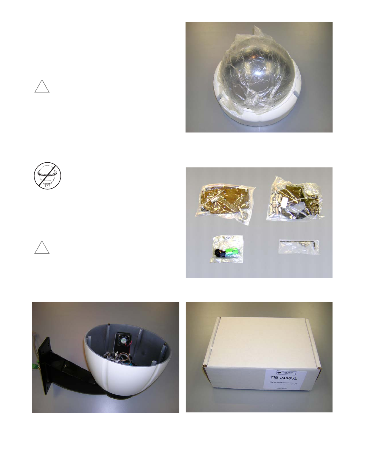
ASSEMBLING THE UNIT:
1. Remove content from all boxes.
Contents should include:
Dome Assembly - Clear or Tinted
Do not remove the protective lm until the product is
assembled and installed.
4 Packet Assemblies
Main Housing Assembly
Either with wall mount or pendant bracket
(2) 40Va Transformers
- 3 -

INSTALLATION OF PTZ CAMERA
See model for specic instruction.
Listed on the following pages are the specic instructions
for each of the individual network cameras. See specic
instruction for the model that matches the unit you have.
INDEX OF CAMERAS
AXIS 213 5
AXIS 214 6
AXIS 231D/232D 7-9
CANON VB-C10R 10
CANON VB-C50iR 11
CANON VC-C4R / VC-C50iR 12
ELMO PTC-200C 13
ELMO PTC-201 14
ELMO PTC-400C 15
ELMO PTC-401 16
JVC VN-C30U 17
JVC VN-C625U / TK-625U 18
JVC VN-C655U 19
PANASONIC BB-HCM381 / KX-HMC280 20
PIXORD 261 / 262 21
SONY SNCRZ25 22
SONY SNCRZ30 23
SONY SNCRZ50 24
TOSHIBA IK-WB21A 25
- 4 -
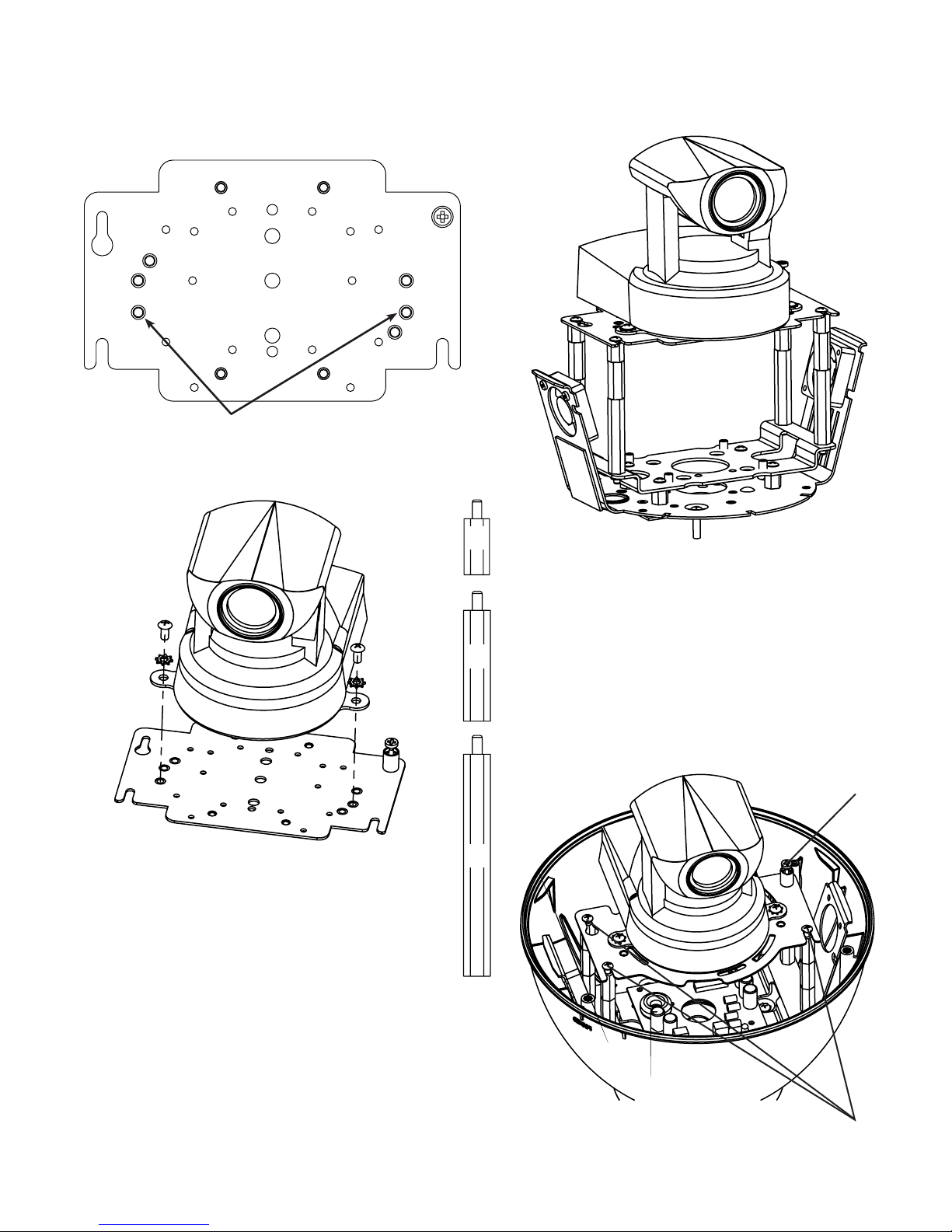
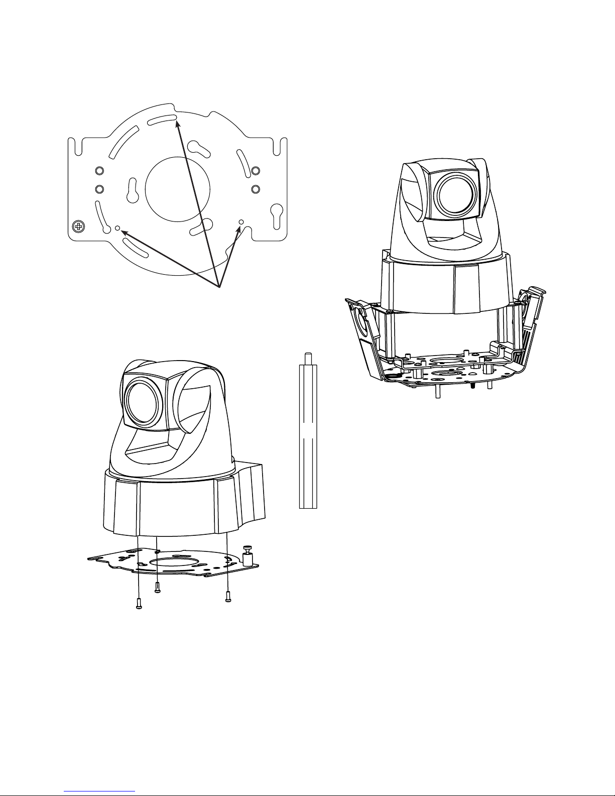
INSTALLING QUICK RELEASE BRACKETS
AXIS 213
2539 Mounting Plate:
Attach camera using these (2) holes
1. Install the camera to the 2539 mounting plate using
(2) 10-32 screws and lockwashers provided.
2. The Axis 213 camera requires 3.5" of spacing for optimal
position within the housing. Use (4) 2" spacer(s), plus
(4) 1" spacer(s) and (4) ½" spacer(s) provided in the (2)
hardware packets.
½"
3. Place (3) 8 x 32 x s Phillips head screws on the top
of the spacer as shown above. Be sure to place the
screws so that they line up with the open slots on the
1"
mounting plate.
4. Slide the mounting plate with camera into position on
top of spacers. Secure 3 screws and captive fastener.
2"
Captive Screw
(3) screws
in housing
- 5 -
INSTALLING QUICK RELEASE BRACKETS
AXIS 214
2685 Mounting Plate:
Attach camera using these (3) holes
1. Install the AXIS 214 camera to the 2685 mounting
plate using the (3) 3mm x 12mm bolt and lock washers
provided.
2. The AXIS 214 camera requires 2” of spacing for optimal
position within the housing. Use the 4 (2”) spacers
provided in the packet.
3. Place (3) 8 x 32 x s Phillips head screws on the top
2"
of the spacer as shown above. Be sure to place the
screws so that they line up with the open slots on the
mounting plate.
4. Slide the mounting plate with camera into position on
top of spacers. Secure 3 screws and captive fastener.
- 6 -

INSTALLING QUICK RELEASE BRACKETS
AXIS 231D/232D
2685 Mounting Plate:
Attach camera using these (3) holes
Keyhole slot (3)
Locking screw
3. Position the locking pins and locking screw over the key
hole slots and twist clockwise. Secure locking screw.
4. The AXIS 231D/232D cameras require ½” of spacing for
½"
optimal position within the housing. Use (4) ½” spacer
provided in the packet.
Loosen screw
Small keyhole
slot
Locking pins
1. The AXIS 231D/232D mounts to the 2685 mounting plate
using the (3) locking pins on the base of the pan tilt.
5. Place (3) 8 x 32 x s Phillips head screws on the top
of the spacer as shown above. Be sure to place the
screws so that they line up with the open slots on the
mounting plate.
6. Slide the mounting plate with camera into position on
top of spacers. Secure 3 screws and captive fastener.
2. Hold pan/tilt with dome facing down, and nd “tab” on
the bottom of the unit. Loosen the screw which is to the
right of the tab by approximately 5 turns.
- 7 -
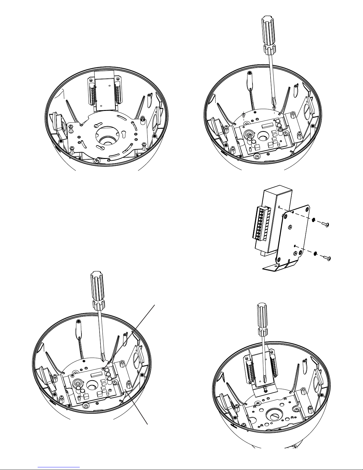
Installing the Axis 231D/232D Camera (cont.)
7. Housing with 2685 mounting plate installed.
8. Since the 231D/232D camera operates on 24Vac, the power
board that is located inside the housing is not needed. The
remove the power board, start by loosening the screws
on the terminal block and disconnect the orange and red
wires.
9. With a Phillips head screwdriver remove the (4) machine
screws holding the power board to the base bracket.
10. Locate the connector
block, which is included
with the camera. Then
locate the connector
block bracket, which
is included with the
housing. Attach the
block to the bracket as
shown in the following
diagram. Use the M3
screws and washers
that are located in the
housing packet.
Machine screws (4)
Base Bracket
11. Attach the connector block assembly to the housing using
(1) 6-32 x s” screw and star washer located in the housing
packet.
- 8 -
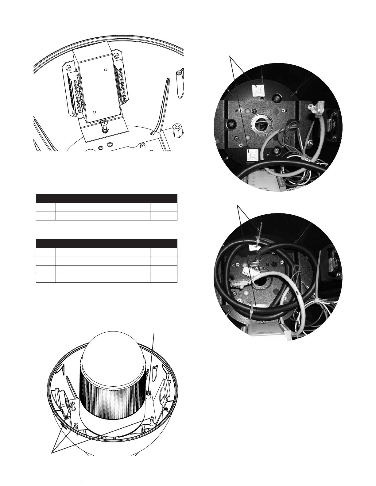
Installing the Axis 231D/232D Camera (cont.)
12. Make wiring connections to connector block assembly per
camera instructions.
For Model 25733 only
POWER
1 Camera Power (24VAC) Red
2 Camera Power (24VAC) Orange
13. To manage the input cable running from the connector
block to the camera use the (2) cable tie mounts and
cable ties that are located in the housing packet.
Cable Tie Mounts
Cable Ties
CONTROL
RJ45 Ethernet Connector
ALARMS
1 Alarm 1 Blue
2 Alarm 2 Violet
3 Alarm 3 Gray
4 Common White
Captive screw
14. Now grab the camera assembly and connector the RJ45
cable and the input cable to the camera (see diagram
opposite).
15. Now attach the camera assembly to the housing by sliding
the (3) open screw slots over the screws in the housing.
Slide the bracket forward, and the tighten the captive
screw on the bracket.
Open screw slots
- 9 -
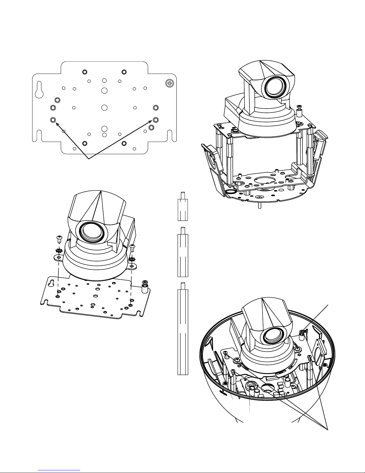
INSTALLING QUICK RELEASE BRACKETS
CANON VB-C10R
2539 Mounting Plate:
Attach camera using these (2) holes
1. Install the camera to the 2539 mounting plate using
(2) 10-32 screws and lockwashers provided.
2. The Canon VB-C10R camera requires 4" of spacing for
optimal position within the housing. Use (4) 2" spacer(s),
plus (4) 1" spacer(s) and (4) ½" spacer(s) provided in the
(2) hardware packets.
½"
3. Place (3) 8 x 32 x s Phillips head screws on the top
of the spacer as shown above. Be sure to place the
screws so that they line up with the open slots on the
1"
mounting plate.
4. Slide the mounting plate with camera into position on
top of spacers. Secure 3 screws and captive fastener.
2"
Captive Screw
(3) screws
in housing
- 10 -
 Loading...