

Moog Videolarm Freedom Dome LDW75C2N Installation And Operation Instructions Manual
© 2012, Moog Videolarm, Inc. All Rights Reserved
F r e e d o m D o m e
Modular All Weather Dome Enclosure
Installation and Operation Instructions for the following model:
LDW75C2N Ruggedized dome enclosure with space for peripheral equipment.
110/220VAC input. Designed to work with Moog Videolarm IP Ready
camera housings.
Before attempting to connect or operate this product, please read these instructions completely.
www.moogvideolarm.com
W81-IN5477
07-25-2012
IMPORTANT SAFEGUARDS SAFETY PRECAUTIONS
1 Read these instructions.
2 Keep these instructions.
3 Heed all warnings
4 Follow all instructions.
5 Do not use this apparatus near water.
6 Clean only with damp cloth.
7 Do not block any of the ventilation openings. Install in accordance with the
manufacturers instructions.
8 Cable Runs- All cable runs must be within permissible distance.
9 Mounting - This unit must be properly and securely mounted to a supporting
structure capable of sustaining the weight of the unit.
Accordingly:
a. The installation should be made by a qualified installer.
b. The installation should be in compliance with local codes.
c. Care should be exercised to select suitable hardware to install the unit, taking into
account both the composition of the mounting surface and the weight of the
unit.
10 Do not install near any heat sources such as radiators, heat registers, stoves, or other
apparatus ( including amplifiers) that produce heat.
11 Do not defeat the safety purpose of the polarized or grounding-type plug. A
polarized plug has two blades with one wider than the other. A grounding type
plug has two blades and a third grounding prong. The wide blade or the third
prong are provided for your safety. When the provided plug does not fit into your
outlet, consult an electrician for replacement of the obsolete outlet.
12 Protect the power cord from being walked on or pinched particularly at plugs,
convenience receptacles, and the point where they exit from the apparatus.
13 Only use attachment/ accessories specified by the manufacturer.
14 Use only with a cart, stand, tripod, bracket, or table specified by the manufacturer,
or sold with the apparatus. When a cart is used, use caution when moving the cart/
apparatus combination to avoid injury from tip-over.
15 Unplug this apparatus during lighting storms or when unused for long periods of time.
16 Refer all servicing to qualified service personnel. Servicing is required when the
apparatus has been damaged in any way, such as power-supply cord or plug is
damaged, liquid has been spilled of objects have fallen into the apparatus, the
apparatus has been exposed to rain or moisture, does not operate normally, or
has been dropped.
Be sure to periodically examine the unit and the supporting structure to make sure that the
integrity of the installation is intact. Failure to comply with the foregoing could result in the
unit separating from the support structure and falling, with resultant damages or injury to
anyone or anything struck by the falling unit.
UNPACKING
Unpack carefully. Electronic components can be
damaged if improperly handled or dropped. If an item
appears to have been damaged in shipment, replace
it properly in its carton and notify the shipper.
Be sure to save:
1 The shipping carton and packaging material.
They are the safest material in which to make
future shipments of the equipment.
2 These Installation and Operating Instructions.
SERVICE
If technical support or service is needed, contact us
at the following number:
CAUTION: TO REDUCE THE RISK OF
ELECTRIC SHOCK, DO NOT REMOVE
COVER ( OR BACK). NO USER- SERVICE-
ABLE PARTS INSIDE. REFER SEVICING TO
QUALIFIED SERVICE PERSONNEL.
The lightning flash with an arrowhead
symbol, within an equilateral triangle, is
intended to alert the user to the presence
of non-insulated “dangerous voltage”
within the product’s enclosure that may be
of sufficient magnitude to constitute a risk
to persons.
Este símbolo se piensa para alertar al usuario a la
presencia del “voltaje peligroso no-aisIado” dentro del
recinto de los productos que puede ser un riesgo de
choque eléctrico.
Ce symbole est prévu pour alerter I’utilisateur à la
presence “de la tension dangereuse” non-isolée dans la
clôture de produits qui peut être un risque de choc
électrique.
Dieses Symbol soll den Benutzer zum Vorhandensein der
nicht-lsolier “Gefährdungsspannung” innerhalb der
Produkteinschließung alarmieren die eine Gefahr des
elektrischen Schlages sein kann.
Este símbolo é pretendido alertar o usuário à presença
“di tensão perigosa non-isolada” dentro do cerco dos
produtos que pode ser um risco de choque elétrico.
Questo simbolo è inteso per avvertire I’utente alla
presenza “di tensione pericolosa” non-isolata all’interno
della recinzione dei prodotti che può essere un rischio di
scossa elettrica
The exclamation point within an equilateral
triangle is intended to alert the user to
presence of important operating and
maintenance (servicing) instructions in the
literature accompanying the appliance.
Este símbolo del punto del exclamation se piensa para
alertar al usuario a la presencia de instrucciones
importantes en la literatura que acompaña la
aplicación.
Ce symbole de point d’exclamation est prévu pour
alerter l’utilisateur à la presence des instructions
importantes dans la littérature accompagnant
l’appareil.
Dieses Ausruf Punktsymbol soll den Benutzer zum
Vorhandensein de wichtigen Anweisungen in der
Literatur alarmieren, die das Gerät begleitet.
Este símbolo do ponto do exclamation é pretendido
alertar o usuário à presença de instruções importantes
na literatura que acompanha o dispositivo.
Questo simbolo del punto del exclamaton è inteso per
avvertire l’utente alla presenza delle istruzioni importanti
nella letteratura che accompagna l'apparecchio.
CAUTION
RISK OF ELECTRIC SHOCK
DO NOT OPEN
.
TECHNICAL SUPPORT
AVAILABLE 24 HOURS
1- 800 - 554 -1124

Limited Warranty for Moog Videolarm Products
Moog Videolarm warrants these products to be free from defects in material or workmanship as follows:
PRODUCT CATEGORY PARTS \ LABOR
All Enclosures and Electronics* Five (5) Years
Poles/PolEvators™/CamEvator Three (3) Years
Warrior Series™/Q-View™/IR Illuminators Five (5) Years
SView Series™ Five (5) Years **6 months if used in auto scan/tour operation
Controllers Five (5) Years
Power Supplies Five (5) Years
EcoKit Three (3) Years
Accessory Brackets Five (5) Years
Liberty Dome Three (3) Years
*DeputyDome™, NiteTrac™, Igloo Dome, PurgeDome™ Three (3) Years **6 months if used in auto scan/tour operation
During the labor warranty period, to repair the Product, Purchaser will either return the defective product, freight prepaid, or deliver it to Moog Videolarm
Inc. Decatur GA. The Product to be repaired is to be returned in either its original carton or a similar package affording an equal degree of protection with
a RMA # (Return Materials Authorization number) displayed on the outer box or packing slip. To obtain a RMA# you must contact our Technical Support
Team at 800.554.1124, extension 101. Moog Videolarm will return the repaired Product freight prepaid to Purchaser. Moog Videolarm is not obligated to
provide Purchaser with a substitute unit during the warranty period or at any time. After the applicable warranty period, Purchaser must pay all labor and/or
parts charges.
The limited warranty stated in these product instructions is subject to all of the following terms and conditions.
TERMS AND CONDITIONS
1. NOTIFICATION OF CLAIMS: WARRANTY SERVICE: If Purchaser believes that the Product is defective in material or workmanship, then written notice with an
explanation of the claim shall be given promptly by Purchaser to Moog Videolarm. All claims for warranty service must be made within the warranty period.
If after investigation Moog Videolarm determines the reported problem was not covered by the warranty, Purchaser shall pay Moog Videolarm for the cost of
investigating the problem at its then prevailing per incident billable rate. No repair or replacement of any Product or part thereof shall extend the warranty period
of the entire Product. The speci c warranty on the repaired part only shall be in effect for a period of ninety (90) days following the repair or replacement of that
part or the remaining period of the Product parts warranty, whichever is greater.
2. EXCLUSIVE REMEDY: ACCEPTANCE: Purchaser’s exclusive remedy and Moog Videolarm’s sole obligation is to supply (or pay for) all labor necessary to repair any
Product found to be defective within the warranty period and to supply, at no extra charge, new or rebuilt replacements for defective parts.
3. EXCEPTIONS TO LIMITED WARRANTY: Moog Videolarm shall have no liability or obligation to Purchaser with respect to any Product requiring service during the
warranty period which is subjected to any of the following: abuse, improper use, negligence, accident, lightning damage or other acts of God (i.e., hurricanes,
earthquakes), modi cation, failure of the end-user to follow the directions outlined in the product instructions, failure of the end-user to follow the maintenance
procedures recommended by the International Security Industry Organization, written in product instructions, or recommended in the service manual for the
Product. Furthermore, Moog Videolarm shall have no liability where a schedule is speci ed for regular replacement or maintenance or cleaning of certain parts
(based on usage) and the end-user has failed to follow such schedule; attempted repair by non-quali ed personnel; operation of the Product outside of the
published environmental and electrical parameters, or if such Product’s original identi cation (trademark, serial number) markings have been defaced, altered,
or removed. Moog Videolarm excludes from warranty coverage Products sold AS IS and/or WITH ALL FAULTS and excludes used Products which have not
been sold by Moog Videolarm to the Purchaser. All software and accompanying documentation furnished with, or as part of the Product is furnished “AS IS”
(i.e., without any warranty of any kind), except where expressly provided otherwise in any documentation or license agreement furnished with the Product. Any
cost associated with removal of defective product and installation of replacement product is not included in this warranty.
4. PROOF OF PURCHASE: The Purchaser’s dated bill of sale must be retained as evidence of the date of purchase and to establish warranty eligibility.
DISCLAIMER OF WARRANTY
EXCEPT FOR THE FOREGOING WARRANTIES, Moog Videolarm HEREBY DISCLAIMS AND EXCLUDES ALL OTHER WARRANTIES, EXPRESS OR IMPLIED,
INCLUDING, BUT NOT LIMITED TO ANY AND/OR ALL IMPLIED WARRANTIES OF MERCHANTABILITY, FITNESS FOR A PARTICULAR PURPOSE AND/OR
ANY WARRANTY WITH REGARD TO ANY CLAIM OF INFRINGEMENT THAT MAY BE PROVIDED IN SECTION 2-312(3) OF THE UNIFORM COMMERCIAL
CODE AND/OR IN ANY OTHER COMPARABLE STATE STATUTE. Moog Videolarm HEREBY DISCLAIMS ANY REPRESENTATIONS OR WARRANTY THAT
THE PRODUCT IS COMPATIBLE WITH ANY COMBINATION OF NON-Moog Videolarm PRODUCTS OR NON-Moog Videolarm RECOMMENDED PRODUCTS
PURCHASER MAY CHOOSE TO CONNECT TO THE PRODUCT.
LIMITATION OF LIABILITY
THE LIABILITY OF Moog Videolarm, IF ANY, AND PURCHASER’S SOLE AND EXCLUSIVE REMEDY FOR DAMAGES FOR ANY CLAIM OF ANY KIND
WHATSOEVER, REGARDLESS OF THE LEGAL THEORY AND WHETHER ARISING IN TORT OR CONTRACT, SHALL NOT BE GREATER THAN THE ACTUAL
PURCHASE PRICE OF THE PRODUCT WITH RESPECT TO WHICH SUCH CLAIM IS MADE. IN NO EVENT SHALL Moog Videolarm BE LIABLE TO PURCHASER
FOR ANY SPECIAL, INDIRECT, INCIDENTAL, OR CONSEQUENTIAL DAMAGES OF ANY KIND INCLUDING, BUT NOT LIMITED TO, COMPENSATION,
REIMBURSEMENT OR DAMAGES ON ACCOUNT OF THE LOSS OF PRESENT OR PROSPECTIVE PROFITS OR FOR ANY OTHER REASON WHATSOEVER.
!!
English
Español
Français
Electrical Specifications
LDW75C2N
Input Power: 110Vac/220Vac 1A/0.5A.
Power Consumption: 1Amp (120 watts) at 120Vac.
Power Output: 96Va at 24Vac, 52 watts heater/blower
Camera Power: 32 watts.
An all pole main switch with a contact of at least 3mm in
each pole shall be incorporated in the electrical installation
of the building.
Energía de entrada: 110Vac/220Vac 1A/0.5A.
Consumo de energía: 1Amp (120 vatios) en 120Vac.
Salida de energía: 96Va en 24Vac, 52 vatios de
calentador/soplador
Energía de la cámara: 32 vatios.
Todo el interruptor principal del poste con un contacto de
por lo menos 3m m en cada poste será incorporado en la
instalación eléctrica del edificio.
Puissance d'entrée : 110Vac/220Vac 1A/0.5A.
Puissance : 1Amp (120 watts) à 120Vac.
Rendement de puissance : 96Va à 24Vac, 52 watts de
réchauffeur/ventilateur
Puissance d'appareil-photo : 32 watts.
Un tout le commutateur principal de poteau avec un
contact au moins de 3mm dans chaque poteau sera
incorporé dans l'installation électrique du bâtiment.
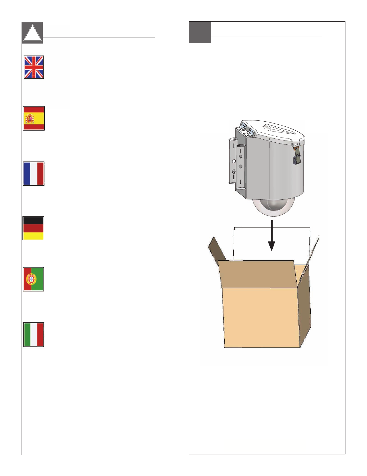
Content of Box
Deutsch
Portuguese
Italiano
Zugeführte Energie: 110Vac/220Vac 1A/0.5A.
Leistungsaufnahme: 1Amp (120 Watt) an 120Vac.
Abgabeleistung: 96Va an 24Vac, 52 Watt Heizung/Gebläse
Kamera-Energie: 32 Watt.
Ein aller Pfostenhauptschalter mit einem Kontakt von 3mm
mindestens in jedem Pfosten wird in der elektrischen
Installation des Gebäudes enthalten.
Poder de entrada: 110Vac/220Vac 1A/0.5A.
Consumo de potência: 1Amp (120 watts) em 120Vac.
Saída de poder: 96Va em 24Vac, 52 watts de
calefator/ventilador
Poder da câmera: 32 watts.
Todo o interruptor principal do pólo com um contato de
3mm em cada pólo será incorporado pelo menos na
instalação elétrica do edifício.
Alimentazione in ingresso di entrata: 110Vac/220Vac
1A/0.5A.
Assorbimento di corrente di energia: 1Amp (120 watt) a
120Vac.
Output di forza motrice: 96Va a 24Vac, 52 watt di
riscaldatore/ventilatore
Potere della macchina fotografica: 32 watt.
Tutto l'interruttore principale del palo con un contatto
almeno di 3mm in ogni palo sarà compreso nell'installazione
elettrica della costruzione.
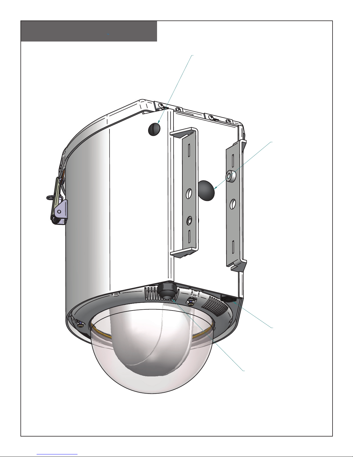
Power Feed Locations:
LIQUID TIGHT PLUG FOR
3G ANTENNA BULKHEAD
CONNECTOR HOLE.
LIQUID TIGHT PLUG FOR
OPTIONAL MAIN
POWER HOLE.
LIQUID TIGHT PLUG FOR
OPTIONAL MAIN
POWER HOLE.
LIQUID TIGHT
STRAIN RELIEF
FOR MAIN POWER HOLE.
Place the housing onto the bracket, secure by
using the provided 2 (M10) bolts and washers.
• Coloque la cubierta sobre el soporte, seguro usando
los 2 pernos (M10) y arandelas proporcionados.
• Placez le logement sur la parenthèse, bloquée en
employant les 2 boulons (M10) et rondelles fournis.
• Setzen Sie das Gehäuse auf dem Haltewinkel, der indem
Sie die zur Verfügung gestellten 2 sicher ist, Schraubbolzen
(M10) und die Unterlegscheiben verwenden.
• Coloc a carcaça no suporte, seguro usando os 2
parafusos (M10) e arruelas fornecidos.
• Disponga l'alloggiamento sulla staffa, sicura usando i 2
bulloni (M10) e rondelle forniti.
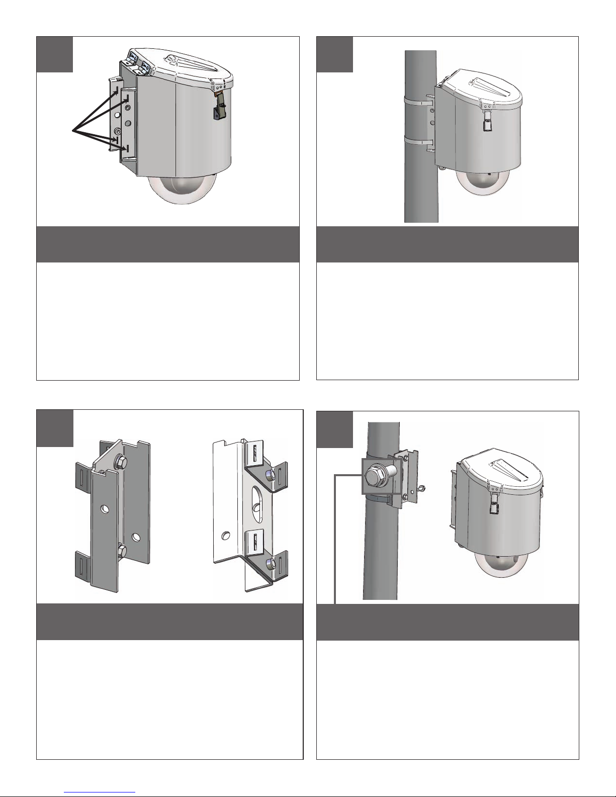
POLE MOUNTING
1 2
Holes for
steel straps
LDW75C2N unit is ready to mount. Use marked
holes to attach steel straps.
• La unidad de LDW75C2N está lista para montar. Utilice
los agujeros marcados para atar las correas de acero.
• L'unité de LDW75C2N est prête à monter. Employez les
trous marqués pour attacher les courroies en acier.
• LDW75C2N Maßeinheit ist bereit anzubringen. Benutzen
Sie markierte Löcher, um Stahlbügel anzubringen.
• A unidade de LDW75C2N está pronta para montar.
Use furos marcados para unir as cintas de aço.
• L'unità di LDW75C2N è pronta a montare. Usi i profondi
fori per attaccare le cinghie d'acciaio.
RAPID DEPLOYMENT POLE MOUNTING WITH POLE MOUNT CLIPS
3
Use the steel straps to mount the unit to a pole.
• Utilice las correas de acero para montar la unidad al
poste.
• Employez les courroies en acier pour monter l'unité au
poteau.
• Benutzen Sie die Stahlbügel, um die Maßeinheit zum
Pfosten anzubringen.
• Use as cintas de aço para montar a unidade ao pólo.
• Usi le cinghie d'acciaio per montare l'unità al palo.
4
Attach pole mount clips to bracket as shown, using
hardware provided.
• Ate los clips del montaje del poste para acorchetar como
se muestra, usando el hardware proporcionado.
• Attachez les agrafes de bâti de poteau à la parenthèse
comme montré, utilisant le matériel fourni.
• Bringen Sie Pfosteneinfassungsclips an, um wie gezeigt
einzuklammern, unter Verwendung der bereitgestellten Hardware.
• Una grampos da montagem do pólo ao suporte como mostrado,
usando a ferragem fornecida.
• Attacchi le clip del supporto del palo alla staffa come indicato,
per mezzo dei fissaggi forniti.
 Loading...