

Moog Videolarm FDW8CS User Manual

!
81-IN5313
FDW8CS
REVISION DATE: June 8, 2005
Unitized Pan/Tilt/Zoom
in Fusion Dome
PRODUCT INSTRUCTIONS
TABLE OF CONTENTS
Description 1
Electrical Specications (Outdoor) 1
Installing the Housing Assembly 1
Preparing Pendant Mount FDP8CS 2
Installing Pendant Mount Housing 2
Wiring Color Code Chart 2
Wiring Gauge Chart 2
Setting Protocol for the Unit 3
Setting the Address for the Unit 3
Optional Settings for the S View 2™ 3
Menu Driven Settings 3
Dipswitch Settings 5
Exploded View 9
Safeguards and Warranty Information 10
Mounting Template 11
DESCRIPTION:
The FDW8CS is a 24 VAC outdoor housing enclosure constructed
of .125 engineered plastic, aluminum and stainless steel. All plastic
components are designed to be UV stable; the housing top is rated
at 94VO. The FDW8CS measures 11.5" (w) x 12.9” (h) x 16" (d), with
a weight of 7 lbs.; measurements for the FDP8CS are 11.5" (w) x
12.9" (h) x 11.5" (d), 7 lbs. Flying leads are provided for all incoming
power, control, and video connections. The leads are supplied with
a standard BNC and (2) screw down connectors. A 25 watt heater
and a circulation blower are also provided. To service, remove the
lower dome and ring assembly.
GENERAL INSTRUCTIONS:
Tools Required: .100" Flat Head Screwdriver
Phillips Head Screwdriver
INSTALLING THE HOUSING ASSEMBLY
FOR WALL MOUNT, FDW8CS
1. FDW8CS
A wall mount bracket comes standard with this unit, and a
template is included to use as a guide for mounting the bracket
to a wall. Choose the desired location for installation, mark
and drill holes using the template. Run approximately 8" of wiring
out of the wall.
2. Open the access door on the bottom of the wall mount by
loosening the screw nearest the mounting plate (Figure 1).
3. Run the wires into the opening on the back of the mount and out
through the access door. Attach the mount and housing to the
wall
with appropriate hardware (no provided).
4. Attach the wires from the wall to the connector provided, using
the
wiring color code chart on page 2 as a guide.
5. Once all wiring connections are made, place the wires inside the
wall mount bracket and close the access door. Secure with the
screw removed earlier.
6. Clean the outside of the dome.
ELECTRICAL SPECIFICATIONS (OUTDOOR):
Power 24VAC, Class 2 Only
55 watts at 24 VAC
27 watts for heater and blower
25 watts for camera
Optional heater/blower assembly: CWKFD2 - 24 VAC cold weather
kit for outdoor FDW(P)8C2 housings
Input Connectors (outdoor units):
BNC
(2) screw-down connectors
NOTE: This unit is designed for operation in an
upright position. Installing the FusionDome™
upside down may cause damage to the
internal equipment, and will void the war-
ranty.
Access door
Figure 1
!
22
250
120
89
65
44
35
29
25
31
19
17
16
14
13
12
11
11
10
9
9
8
20
400
180
141
90
70
56
47
40
34
31
28
25
23
21
20
18
17
16
15
14
14
18
600
300
225
130
112
90
75
64
55
50
45
41
37
34
32
30
28
26
25
23
22
16
960
480
358
225
179
143
119
102
85
79
71
65
59
55
51
47
44
42
39
37
35
14
-
800
571
350
285
228
190
163
140
126
114
103
95
87
81
76
71
67
63
60
57
12
-
1300
905
525
452
362
301
258
215
201
181
164
150
139
129
120
113
106
100
95
90
10
-
-
1440
830
720
576
480
411
340
320
288
261
240
221
205
192
180
169
160
151
144
5.5
10
20
30
40
50
60
70
80
90
100
110
120
130
140
150
160
170
180
190
200
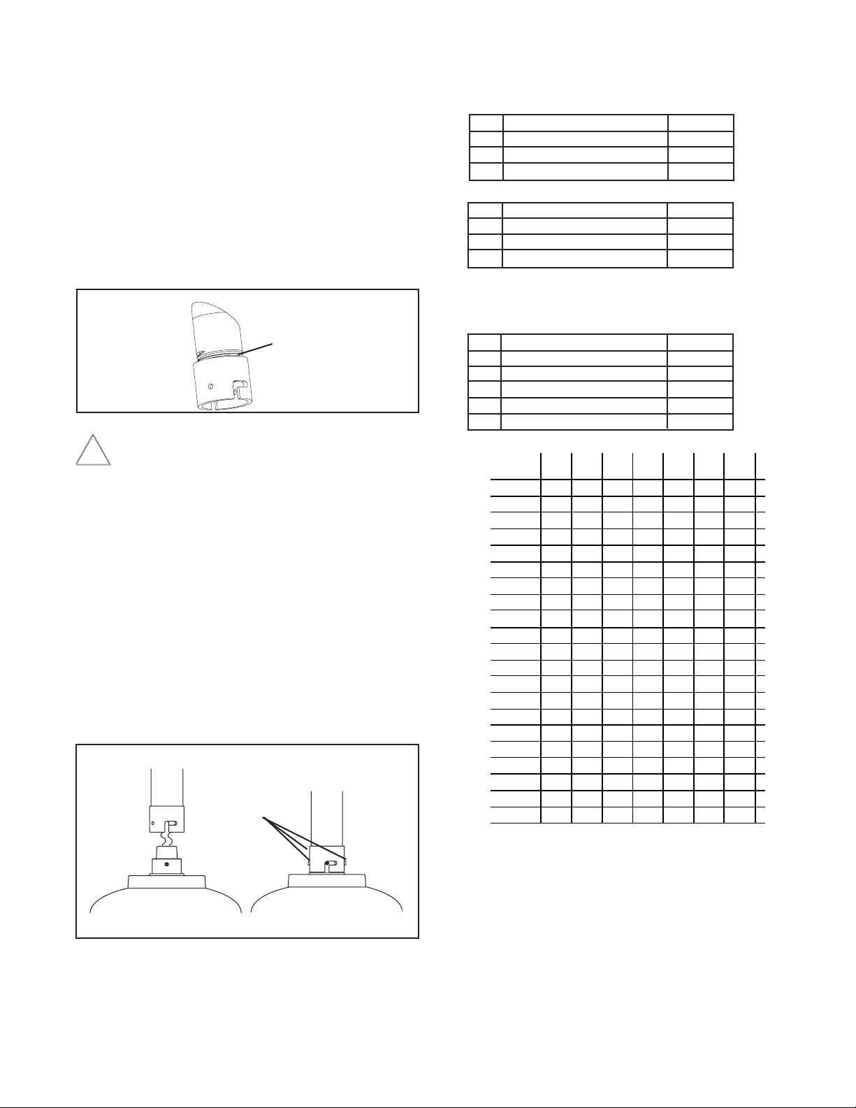
Maximum distance from transformer to load
Total vA consumed
Wire Gauge
Table A. 24 VAC Wiring Distances
The following are the recommended maximum distances for 24VAC with a
10% voltage drop. (10% is generally the maximum allowable voltage drop
for AC-powered devices.)
CABLE DISTANCE CHART
PREPARING PENDANT MOUNT BRACKET FOR
FDP8CS
1. Carefully remove the housing from the packaging material. Check
to be sure all parts are present.
2. This unit includes a 1 1/2" NPT housing for a standard 1 1/2"
NPT
pipe. The FDP8CS can be used with other brackets designed
with 1 1/2" male pipe threads, such as the Videolarm WM20G
and
WM20 wall mount brackets.
Add thread sealing tape
Figure 2
Be sure the bracket is properly and securely mounted to a
supporting structure capable of rigidly holding the weight
of the entire unit.
Wiring Color Code
Power and Control Inputs
(Outside of housing)
POWER
1 Camera Power (24 VAC) Red
2 Camera Power (24 VAC) Orange
3 Heater/Blower Power (24 VAC) Yellow
4 Heater/Blower Power (24 VAC) Green
CONTROL
1 RS-485RXB (+) Blue
2 RS-485RXA (-) Violet
3 RS-485TXA (-) Gray
4 RS-485TXB (+) White
Power and Control Outputs
(Inside of housing)
POWER AND CONTROL LEADS
1 Camera Power (24 VAC) Red
2 Camera Power (24 VAC) Orange
3 RS-485RXB (+) Blue
4 RS-485RXA (-) Violet
5 RS-485TXA (-) Gray
6 RS-485TXB (+) White
FOR PENDANT MOUNT, FDP8CS
1. Mount the housing assembly to the mounting bracket and
housing coupling. A safety cable is included with the housing to
temporarily hold it while making wiring connections. Loop the
safety cable over one of the set screws on the housing coupling
and make the appropriate connections using the (2) screw-down
connectors supplied.
2. Undo the safety cable and twist the housing onto the housing
coupling. Secure all (3) setscrews provided on the housing
coupling (Figure 3).
Twist and
Secure
3. Clean the outside of the dome.
Figure 3
-2 -
The FDW8CS is setup with (2) individual power inputs.
1. Accessory Power (yellow and green wire)
2. Camera Power (red and orange)
If you wish to provide a single power transformer:
OPTIONAL SETTINGS FOR THE S VIEW 2™
Protocols
The S View 2™ supports VL422, Pelco P, and Pelco D protocols. The
protocol is sensed automatically so there are no dip switches or adjustments for setting the protocol.
1. Be certain that you know the total power consumption of the
hous-
ing Heaters (25 watts) + Blowers (2 watts) + camera/pan-tilt (25
watts)
2. Check the supplied wiring chart to be sure that you have the
proper gauge wire for the distance that you intend to run your
power wires.
3. Bring power to the 3 and 4 position of the power connector (yel-
low
and green wire)
4. Two jumpers are provided in the housing packet. Jumper from
the
1st position to the 3rd position and from the 2nd position to the 4th
Add 2 jumpers for
single power input
Figure 4
Day/Night Camera
When the light level is low, the camera will switch out the infrared lter
and go to black and white mode. This feature can be permanently
turned off, on, or set to automatic mode by using the menu in the On
Screen Display.
Zones
There are 16 zones that may be programmed in the S View 2™. Each
zone may be set as a privacy zone with the video off. The zone title, if
programmed and enabled, will be displayed regardless of whether the
zone is programmed for privacy or not.
Presets
The S View 2™ has 64 presets that can be used individually or as part
of an auto tour. Preset 1 is the “home preset”; In addition, some presets
have special functions as shown in the table below:
PRESET
NUMBER COMMAND FUNCTION
66 GO TO Show this table
70 GO TO Start Auto Tour
80 GO TO Run Pattern
80 SET Start Recording Pattern
81 SET Stop Recording Pattern
89 GO TO Put Camera Into Auto Iris Mode
95 GO TO Display Main Menu
SETTING PROTOCOL FOR THE UNIT
There are no user settings for protocol selection. The S View 2™ will
respond to Pelco D, Pelco P, or Videolarm VL422 protocol automati-
cally (1 start bit, 1 stop bit, 8 data bits, no parity).
Factory Settings
DO NOT ADJUST
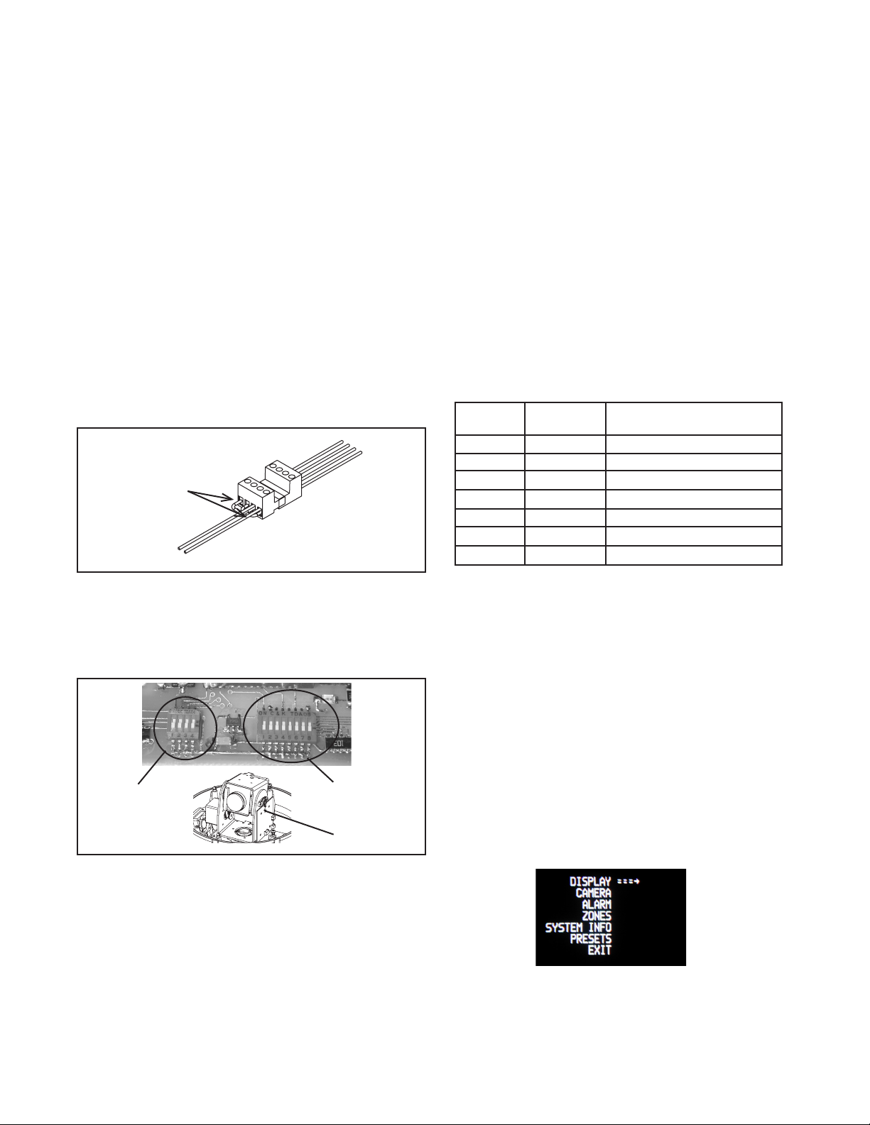
SETTING THE ADDRESS FOR THE UNIT
Each pan/tilt must have its own unique address. The factory
default address is 001 . To change this address use the 8 position
dip switch located on the PC Board on the side of the pan/tilt (Figure
4), referring to the chart in the back of this manual. The address is
set with the rocker style dip switches, which are non-volatile. The
address cannot be changed unless the dip switches are moved, or
unless the Remote Address feature in the VLC485 software is used.
Address
Dip Switches
PC Board
located here
Auto Tour
The auto tour function will automatically go, in sequence, to each
preset that has been programmed. The dwell time for each preset
can be set individually to be from 0 to 99 seconds.
NOTE: When the dwell time is set to "0" the preset will be replaced
by
the pattern (see below for setting). The pattern will execute,
then auto tour will resume. More than one preset may be
replaced by the pattern.
Pattern (See page 5)
A pattern is a programmed continuous path. The camera will follow
this path repeatedly until the pattern is stopped. One pattern, with a
maximum pattern time of 128 seconds, can be set. To set a pattern
MENU DRIVEN SETTINGS
To enter the Main Menu, go to preset 95. The picture will disappear
When you are in the Main Menu pan and tilt functions will not control
the motion of the pan/tilt (except where noted). Instead, “Tilt Up”
or “Tilt Down” will be used to navigate up or down along the main
menu. "Pan Right” and “Pan Left” will be used to select between the
main menu selection and the sub menu. The “Zoom In” and “Zoom
Out” are used to turn the selected functions on or off.
-3 -

DISPLAY - This controls the display of the compass heading and
allows the user to calibrate the compass heading. PAN RIGHT to
access the sub-menu. TILT DOWN to access each item. PAN LEFT
to return to the main menu.
COMPASS - The display show “COMPASS ON” or “COMPASS
OFF”. Press “zoom in” to turn the compass heading on and
“zoom
out’ to turn the compass display off.
SET NORTH - Press “zoom in” button to set calibration. The
display will show “OK”.
POSITION - This displays the pan and tilt positions of the camera.
Press "zoom in" to turn this on, "zoom out" to turn it off.
ADDRESS - This displays the camera address. Press "zoom in"
to
turn this on, "zoom out" to turn it off.
BACKLIGHT - Controls backlight compensation. Press "zoom in"
to turn this on, "zoom out" to turn it off.
AGC - Selects automatic AGC or minimum AGC (0db). Press
"zoom in" to turn this on, "zoom out" to turn it off.
DIGI ZOOM - Turns the digital zoom on and off. Press "zoom in"
to
ALARM - To get to this section, tilt down from the CAMERA menu.
This menu allows the user to control the operation of the alarm input.
If the alarm is enabled, the camera will go to preset 1. Press "zoom
in" to enable, press "zoom out" to disable.
ZONES - Up to 16 zones may be selected, each zone has a number
of parameters associated with it. Pan Right to access Zones.
"ZONE 1" will display.
TEMP - This displays the temperature sensor data on the tilt
board. Press "zoom in" to turn this on, "zoom out" to turn it off.
NOTE: This reading will be higher than the actual ambient
temperature in the dome. This is for diagnostic use only.
CAMERA - The “CAMERA” sub-menu is used to control several of
the camera’s parameters. PAN RIGHT to access the sub-menu. TILT
DOWN to access each item.
NOTE: When this sub menu is accessed the camera picture will
return to allow adjustments.
STABILIZER - Stabilizer, where equipped, compensates for
small
movements or vibrations when the camera is “zoomed in”. Press
"zoom in" to turn this on, "zoom out" to turn it off.
DAY/NIGHT - This is used to control the low light mode of the
camera. There are three choices:
AUTO - The camera will automatically switch into day/night
mode for low light conditions.
DAY - The camera will be in the day mode continuously.
NIGHT - The camera will be in the night mode continuously.
Press "zoom in" to cycle through the choices. P
SHUTTER - Selects between auto and manual shutter speeds.
Press "zoom in" to cycle up through the selections, or "zoom out"
to cycle down.
"Tilt up" or "Tilt down" to select the zone desired. Once the zone is
selected, "Pan Right" to access the sub-menu.
SHOW - Allows the title to be displayed. Press "zoom in" to
turn this on, "zoom out" to turn it off.
PRIVATE - Determines if this will be a privacy zone. Press "zoom
in" to turn this on, "zoom out" to turn it off.
RLIMIT - Sets the pan right limit for the zone. The current pan
limit
will be displayed. Press "zoom out", the picture will reappear and
you will have pan control. Pan to the desired location. Press
"zoom
in" to select. The new pan limit will appear.
LLIMIT - Sets the pan left limit for the zone. The current pan limit
will be displayed. Press "zoom out", the picture will reappear and
you will have pan control. Pan to the desired location. Press
"zoom
in" to select. The new pan limit will appear.
NOTE: The picture will displayed whenever you are in RLIMIT
-4 -
 Loading...