

Moog Videolarm FDW7 FusionDome Installation And Operation Instructions Manual
© 2009, Videolarm, Inc. All Rights Reserved
FDW7
FusionDome™ Series
Installation and Operation Instructions for the following models:
FDW7
Before attempting to connect or operate this product,
please read these instructions completely.
www.videolarm.com
CERTIFIED
81-IN5324
02-02-2009
!
1. Read Instructions - All the safety and operating instructions should be read
!
before the unit is operated.
2. Retain Instructions - The safety and operating instructions should be retained
for future reference.
3. Heed Warnings - All warnings on the unit and in the operating instructions
should be adhered to.
4. Follow Instructions - All operating & user instructions should be followed.
5. Electrical Connections - Only a qualified electrician should make electrical
connections.
6. Attachments - Do not use attachments not recommended by the product
manufacturer as they may cause hazards.
7. Cable Runs - All cable runs must be within permissible distance.
8. Mounting - This unit must be properly and securely mounted to a supporting
structure capable of sustaining
a. Installation should be made by a qualified installer.
b. Installation should be in compliance with local codes.
c. Care should be exercised to select suitable hardware to install the unit,
taking into account both the composition of the mounting surface and
the weight of the unit. Be sure to periodically examine the unit and the
supporting structure to make sure that the integrity of the installation
is intact. Failure to comply with the foregoing could result in the unit
separating from the support structure and falling, with resultant damages
or injury to anyone or anything struck by the falling unit.
UNPACKING
Unpack carefully. Electronic components can be damaged if improperly handled
or dropped. If an item appears to
properly in its carton and notify the shipper. Be sure to save:
1. The shipping carton and packaging material. They are the safest material in
which to make future shipments of the equipment.
2. These Installation and Operating Instructions.
the weight of the unit. Accordingly:
have been damaged in shipment, replace it
SAFETY PRECAUTIONSIMPORTANT SAFEGUARDS
CAUTION
RISK OF
ELECTRIC SHOCK!
CAUTION: TO REDUCE THE RISK OF
ELECTRICAL SHOCK, DO NOT EXPOSE
COMPONENTS TO WATER OR MOISTURE.
The lightning flash with an arrowhead symbol, within an
equilateral triangle, is intended to alert the user to the
presence of non-insulated "dangerous voltage" within the
product's enclosure that may be of sufficient magnitude
to constitute a risk of electric shock to persons.
The exclamation point within an equilateral triangle is
intended to alert the user to presence of important operating
and maintenance (servicing) instructions in the literature
accompanying the appliance.
SERVICE
If the unit ever needs repair service, customer should contact Videolarm
(1-800-554-1124) for return authorization & shipping instructions.
TECHNICAL SUPPORT
Videolarm has set-up a 24 hour technical support line for their customers.
24 HOUR TECHNICAL SUPPORT
1-800-554-1124
LIMITED WARRANTY FOR VIDEOLARM INC. PRODUCTS
VIDEOLARM INC. warrants this Product to be free from defects in material or workmanship, as follows:
PRODUCT CATEGORY PARTS LABOR
All Enclosures and Electronics Five (5) Years Five (5) Years
Pan/Tilts Three (3) Years **6 months if used in autoscan Three (3) Years **6 months if used in autoscan
Poles/PoleEvators Three (3) Years Three (3) Years
Warrior/Q-View/I.R. Illuminators Five (5) Years Five (5) Years
SView Series Five (5)Years Five (5) Years
Controllers Five (5) Years Five (5) Years
Power Supplies Five (5) Years Five (5) Years
ry Brackets Five (5) Years Five (5) Years
Accesso
During the labor warranty period, to repair the Product, Purchaser will either return the defective product, freight prepaid, or deliver it to Videolarm Inc. Decatur GA.
The Product to be repaired is to be returned in either its original carton or a similar package affording an equal degree of protection with a RMA # (Return Materials
Authorization number) displayed on the outer box or packing slip. To obtain a RMA# you must contact our Technical Support Team at 800.554.1124, extension 101.
Videolarm will return the repaired Product freight prepaid to Purchaser. Videolarm is not obligated to provide Purchaser with a substitute unit during the warranty
period or at any time. After the applicable warranty period, Purchaser must pay all labor and/or parts charges.
ted warranty stated in these product instructions is subject to all of the following terms and conditions:
The limi
1. NOTIFICATION OF CLAIMS: WARRANTY SERVICE: If Purchaser believes that the Product is defective in material or workmanship, then written notice
with an explanation of the claim shall be given promptly by Purchaser to Videolarm but all claims for warranty service must be made within the warranty period.
If after investigation Videolarm determines that the reported problem was not covered by the warranty, Purchaser shall pay Videolarm for the cost of investigating
the problem at its then prevailing per incident billable rate. No repair or replacement of any Product or part thereof shall extend the warranty period as to the entire
Product. The specific warranty on the repaired part only shall be in effect for a period of ninety (90) days following the repair or replacement of that part
remaining period of the Product parts warranty, whichever is greater.
2. EXCLUSIVE REMEDY: ACCEPTANCE: Purchaser’s exclusive remedy and Videolarm’s sole obligation is to supply (or pay for) all labor necessary to repair
any Product found to be defective within the warranty period and to supply, at no extra charge, new or rebuilt replacements for defective parts.
3. EXCEPTIONS TO LIMITED WARRANTY: Videolarm shall have no liability or obligation to Purchaser with respect to any Product requiring service during
the warranty period which is subjected to any of the following: abuse, improper use: negligence, accident, lightning damage or other acts of God (i.e., hurricanes,
earthquakes), modification, failure of the end-user to follow the directions outlined in the product instructions, failure of the end-user to foll
procedures recommended by the International Security Industry Organization, written in product instructions, or recommended in the service manual for the Product.
Furthermore, Videolarm shall have no liability where a schedule is specified for regular replacement or maintenance or cleaning of certain parts (based on usage)
and the end-user has failed to follow such schedule; attempted repair by non-qualified personnel; operation of the Product outside of the published environmental
and electrical parameters, or if such Product’s original identification (trademark, serial number) markings have been defaced, altered, or removed. Videolarm
excludes from warranty coverage Products sold AS IS and/or WITH ALL FAULTS and excludes used Products which have not been sold by Videolarm to the Purchaser.
All software and accompanying documentation furnished with, or as part of the Product
expressly provided otherwise in any documentation or license agreement furnished with the Product.
4. PROOF OF PURCHASE: The Purchaser’s dated bill of sale must be retained as evidence of the date of purchase and to establish warranty eligibility.
DISCLAIMER OF WARRANTY
INCLUDING, BUT NOT LIMITED TO ANY AND/OR ALL IMPLIED WARRANTIES OF MERCHANTABILITY, FITNESS FOR A PARTICULAR PURPOSE AND/OR ANY WARRANTY WITH REGARD TO ANY CLAIM
OF INFRINGEMENT THAT MAY BE PROVIDED IN SECTION 2-312(3) OF THE UNIFORM COMMERCIAL CODE AND/OR IN ANY OTHER COMPARABLE STATE STATUTE. VIDEOLARM HEREBY DISCLAIMS
ANY REPRESENTATIONS OR WARRANTY THAT THE PRODUCT IS COMPATIBLE WITH ANY COMBINATION OF NON-VIDEOLARM PRODUCTS OR NON-VIDEOLARM RECOMMENDED PRODUCTS
PURCHASER CHOOSES TO CONNECT TO PRODUCT.
LIMITATION OF LIABILITY THE LIABILITY OF VIDEOLARM, IF ANY, AND PURCHASER’S SOLE AND EXCLUSIVE REMEDY FOR DAMAGES FOR ANY CLAIM OF ANY KIND WHATSOEVER,
REGARDLESS OF THE LEGAL THEORY AND WHETHER ARISING IN TORT OR CONTRACT, SHALL NOT BE GREATER THAN THE ACTUAL PURCHASE PRICE OF THE PRODUCT WITH RESPECT TO WHICH
SUCH CLAIM IS MADE. IN NO EVENT SHALL VIDEOLARM BE LIABLE TO PURCHASER FOR ANY SPECIAL, INDIRECT, INCIDENTAL, OR CONSEQUENTIAL DAMAGES OF ANY KIND INCLUDING, BUT NOT
LIMITED TO, COMPENSATION, REIMBURSEMENT OR DAMAGES ON ACCOUNT OF THE LOSS OF PRESENT OR PROSPECTIVE PROFITS OR FOR ANY OTHER REASON WHATSOEVER.
EXCEPT FOR THE FOREGOING WARRANTIES, VIDEOLARM HEREBY DISCLAIMS AND EXCLUDES ALL OTHER WARRANTIES, EXPRESS OR IMPLIED,
/ tour operation
**6 months if used in autoscan
/ tour operation
is furnished “AS IS” (i.e., without any warranty of any kind), except where
/ tour operation
**6 months if used in autoscan
/ tour operation
or the
ow the maintenance
DESCRIPTION:
The FDW7 Housing is a Vandal Resistant Housing especially de-
signed for integrated pan/tilt units. The housing top is made of high
impact Lexan
UV stable, polycarbonate plastic. The FDW7 housing measures
10” (w) x 13 (h) and 14.75” (d) with a weight of 8.25 lbs. Flying
leads are provided for all power, control and video connections. The
leads are supplied with a standard BNC and (2) screw down con-
nectors. A 25W heater (25 watts total) with a circulation fan is also
supplied.
®
while the lower dome is made of an optically clear,
ELECTRICAL SPECIFICATIONS (OUTDOOR
ONLY):
Power 24VAC, Class 2 Only
!
26 watts at 24 VAC (accessories)
Heater: 25 watts
Blower: 1 watt
Input Connectors (outdoor units):
BNC
(2) screw-down connectors
NOTE: This unit is designed for operation in an upright
position. Installing the FDW7 upside down may
cause damage to the internal equipment, and
will void the warranty.
INSTALLING QUICK RELEASE BRACKET AND
PAN/TILT CAMERA ASSEMBLY (ALL MODELS)
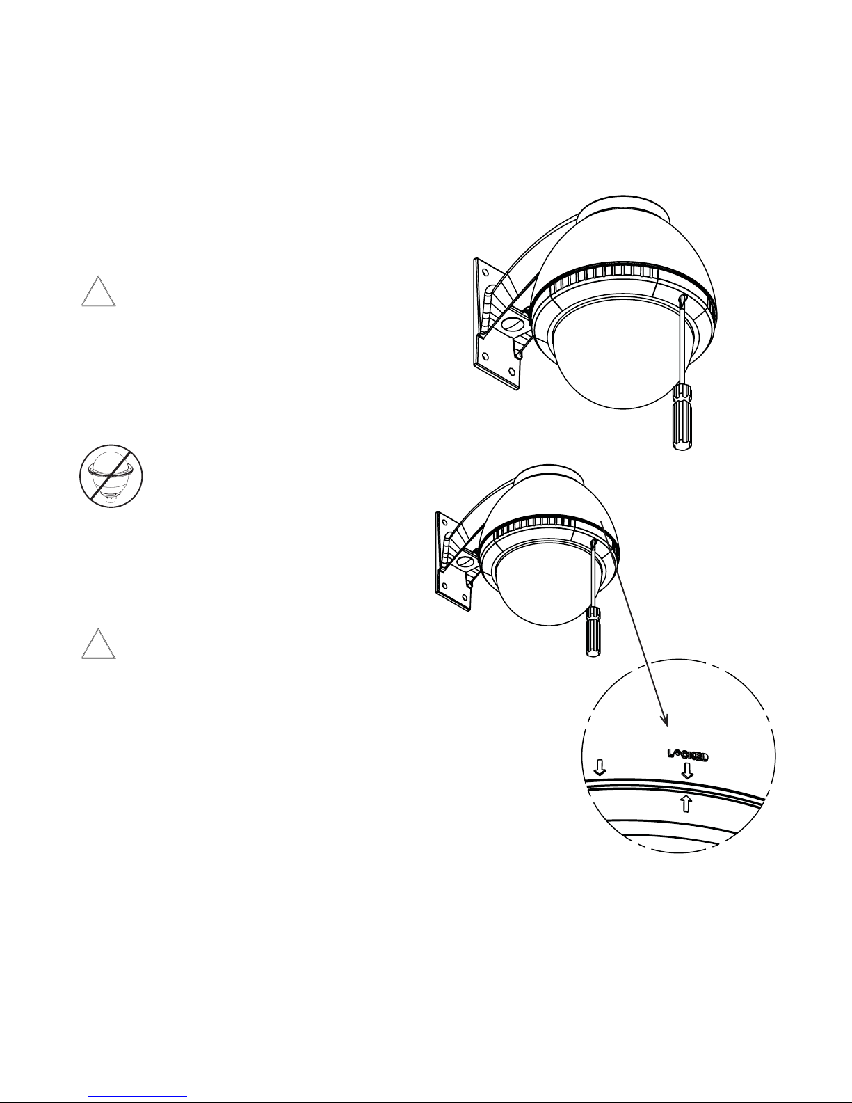
1. Open the housing by loosening the screw on the front of the dome
trim ring (Figure 1). Note the arrows and the word "Locked" on the
side of the housing and trim ring. Rotate the trim ring until the
bottom arrow aligns with the second top arrow, then pull the dome
and trim ring off.
GENERAL INSTRUCTIONS:
Tools Required: .100" Flat Head Screwdriver
Phillips Head Screwdriver
Be sure the bracket is properly and securely mounted to a
supporting structure capable of rigidly holding the weight of
!
the entire unit.
Figure 1
2. Install the pan/tilt unit quick-release bracket. It is recommended
that this be done before installing the housing. Instructions for
mounting quick-release brackets from selected manufacturers are
on page 4.
3. Clean the inside of the dome and reattach. Do not overtighten
the screw. Tighten only to the point at which the gap between the
ring and the housing top closes.
-3 -
-3 -
INSTALLING THE HOUSING ASSEMBLY
INSTALLING OPTIONAL PENDANT MOUNT
FOR WALL MOUNT, FDW7
A wall mount bracket comes standard with this unit, and a
template is included to use as a guide for mounting the bracket
to a wall. Choose the desired location for installation and mark
the drill holes using the template. Screw (2) bolts (not
provided) about 3/4 of the way into the (2) top holes. Run
approximately 8" of wiring out of the wall.
NOTE: Be sure the hardware and the mounting surface can sup-
port the weight of the wall mount bracket plus the weight
of the housing and drive unit. The load will be subjected
to vibration from the camera motor and wind.
2. The wall mount bracket provided with the FDW7 includes
a location for conduit entry. If you wish to install conduit to the
bracket remove the conduit hole plug. Install fitting from below the
wall mount and secure with conduit nut from inside the bracket.
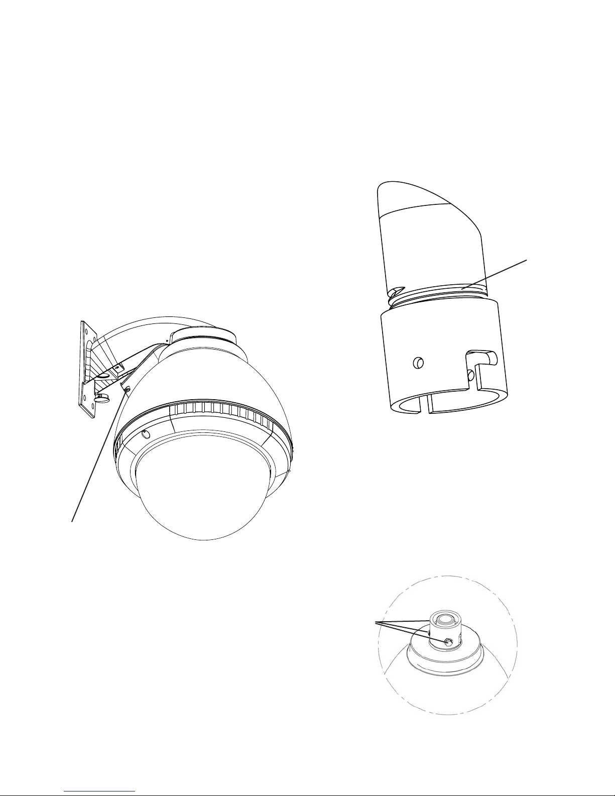
3. Open the access door on the bottom of the wall mount by
loosening the screw nearest the mounting plate (Figure 2).
1. This unit includes a 1 1/2" NPT housing for a standard 1 1/2"
NPT pipe. The FD7 can be used with other brackets
designed with 1 1/2" male pipe threads, such as the Videolarm
WM20G and WM20 wall mount brackets.
2. Attach the housing coupling (Figure 3).
NOTE: Pipe threads should be clean and rust free.
Use a sealer (such as Teflon™ tape or silicone
sealer) on the threads.
Add thread
Figure 3
sealing tape
Access panel
Figure 2
4. Attach the wires from the wall to the connector provided, using the
wiring color code chart as a guide.
5. Once all wiring connections are made, place the wires inside the
wall mount bracket and close the access door. Secure with the
screw removed earlier.
6. Clean the outside of the dome.
1. Mount the housing assembly to the mounting bracket and
housing coupling. A safety cable is included with the housing to
temporarily hold it while making wiring connections. Loop the
safety cable over one of the set screws on the housing coupling
and make the appropriate connections using the (2) screw-down
connectors supplied.
2. Undo the safety cable and twist the housing onto the housing
coupling. Secure all (3) setscrews provided on the housing
coupling (Figure 4).
Set screws
Figure 4
3. Clean the outside of the dome.
-4 -
 Loading...