

Page 1
© 2012, Moog Videolarm, Inc. All Rights Reserved
A P 1 6 C S - 3 S T
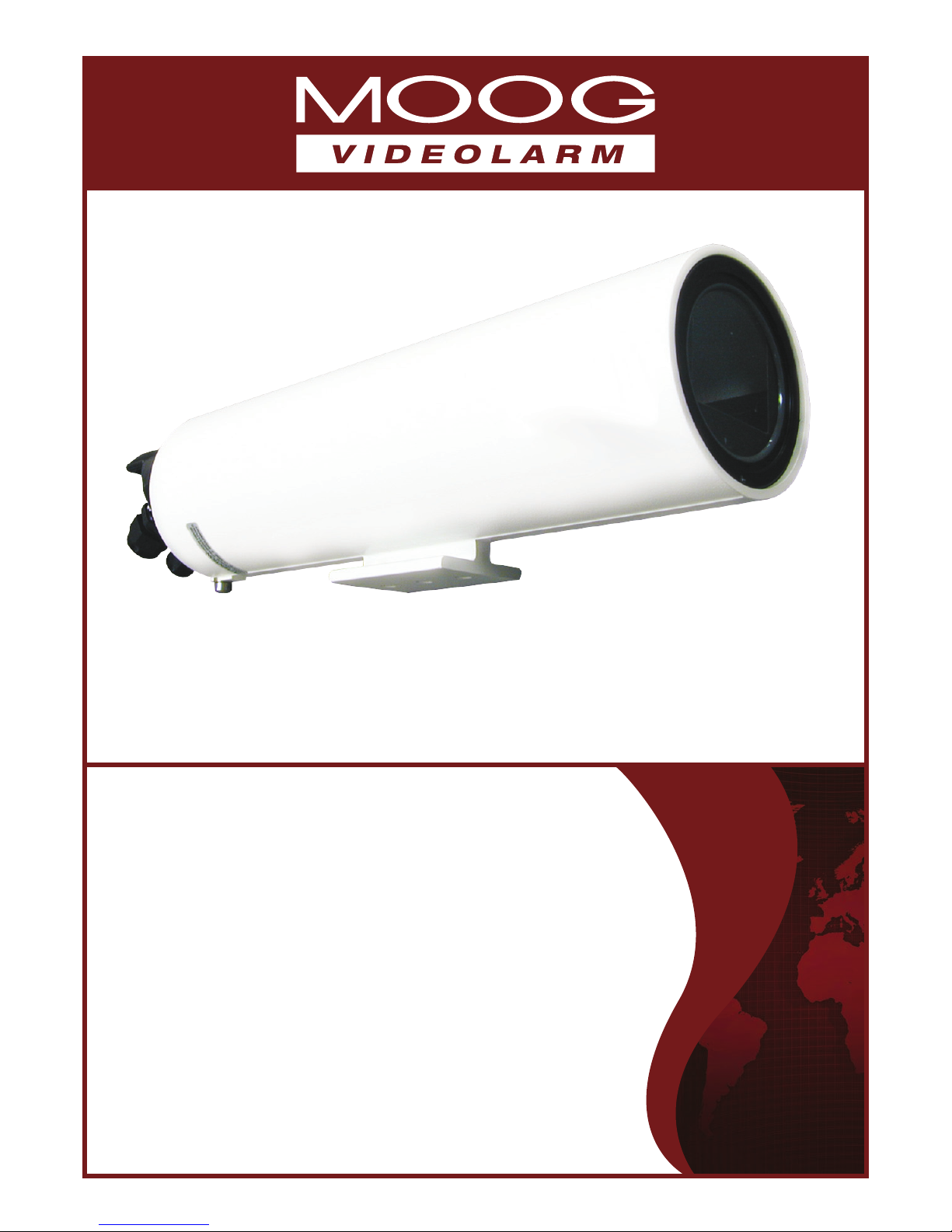
Outdoor Tubular Pressurized Environmental Housing
Before attempting to connect or operate this product, please read these instructions completely.
www.moogvideolarm.com
81-IN5485
08-16-2012
Page 2
IMPORTANT SAFEGUARDS SAFETY PRECAUTIONS
1 Read these instructions.
2 Keep these instructions.
3 Heed all warnings
4 Follow all instructions.
5 Do not use this apparatus near water.
6 Clean only with damp cloth.
7 Do not block any of the ventilation openings. Install in accordance with the
manufacturers instructions.
8 Cable Runs- All cable runs must be within permissible distance.
9 Mounting - This unit must be properly and securely mounted to a supporting
structure capable of sustaining the weight of the unit.
Accordingly:
a. The installation should be made by a qualied installer.
b. The installation should be in compliance with local codes.
c. Care should be exercised to select suitable hardware to install the unit, taking into
account both the composition of the mounting surface and the weight of the unit.
10 Do not install near any heat sources such as radiators, heat registers, stoves, or other
apparatus ( including ampliers) that produce heat.
11 Do not defeat the safety purpose of the polarized or grounding-type plug. A
polarized plug has two blades with one wider than the other. A grounding type
plug has two blades and a third grounding prong. The wide blade or the third
prong are provided for your safety. When the provided plug does not t into your
outlet, consult an electrician for replacement of the obsolete outlet.
12 Protect the power cord from being walked on or pinched particularly at plugs,
convenience receptacles, and the point where they exit from the apparatus.
13 Only use attachment/ accessories specied by the manufacturer.
14 Use only with a cart, stand, tripod, bracket, or table specied by the manufacturer,
or sold with the apparatus. When a cart is used, use caution when moving the cart/
apparatus combination to avoid injury from tip-over.
15 Unplug this apparatus during lighting storms or when unused for long periods of time.
16 Refer all servicing to qualied service personnel. Servicing is required when the
apparatus has been damaged in any way, such as power-supply cord or plug is
damaged, liquid has been spilled of objects have fallen into the apparatus, the
apparatus has been exposed to rain or moisture, does not operate normally, or
has been dropped.
Be sure to periodically examine the unit and the supporting structure to make sure that the integrity
of the installation is intact. Failure to comply with the foregoing could result in the unit separating
from the support structure and falling, with resultant damages or injury to anyone or anything struck
by the falling unit.
CAUTION: TO REDUCE THE RISK OF
ELECTRIC SHOCK, DO NOT REMOVE
COVER ( OR BACK). NO USER- SERVICE-
ABLE PARTS INSIDE. REFER SEVICING
TO QUALIFIED SERVICE PERSONNEL.
The lightning ash with an arrowhead symbol,
within an equilateral triangle, is intended to
alert the user to the presence of non-insulated
“dangerous voltage” within the product’s
enclosure that may be of sufcient magnitude
to constitute a risk to persons.
Este símbolo se piensa para alertar al usuario a la presencia
del “voltaje peligroso no-aisIado” dentro del recinto de los
productos que puede ser un riesgo de choque eléctrico.
Ce symbole est prévu pour alerter I’utilisateur à la presence
“de la tension dangereuse” non-isolée dans la clôture de
produits qui peut être un risque de choc électrique.
Dieses Symbol soll den Benutzer zum Vorhandensein der
nicht-lsolier “Gefährdungsspannung” innerhalb der
Produkteinschließung alarmieren die eine Gefahr des
elektrischen Schlages sein kann.
Este símbolo é pretendido alertar o usuário à presença “di
tensão perigosa non-isolada” dentro do cerco dos produtos
que pode ser um risco de choque elétrico.
Questo simbolo è inteso per avvertire I’utente alla presenza
“di tensione pericolosa” non-isolata all’interno della
recinzione dei prodotti che può essere un rischio di scossa
elettrica
.
The exclamation point within an equilateral
triangle is intended to alert the user to
presence of important operating and
maintenance (servicing) instructions in the
literature accompanying the appliance.
UNPACKING
Unpack carefully. Electronic components can be
damaged if improperly handled or dropped. If an item
appears to have been damaged in shipment, replace
it properly in its carton and notify the shipper.
Be sure to save:
1 The shipping carton and packaging material.
They are the safest material in which to make future
shipments of the equipment.
2 These Installation and Operating Instructions.
Este símbolo del punto del exclamation se piensa para
alertar al usuario a la presencia de instrucciones importantes
en la literatura que acompaña la aplicación.
Ce symbole de point d’exclamation est prévu pour alerter
l’utilisateur à la presence des instructions importantes dans
la littérature accompagnant l’appareil.
Dieses Ausruf Punktsymbol soll den Benutzer zum
Vorhandensein de wichtigen Anweisungen in der Literatur
alarmieren, die das Gerät begleitet.
Este símbolo do ponto do exclamation é pretendido alertar o
usuário à presença de instruções importantes na literatura
que acompanha o dispositivo.
Questo simbolo del punto del exclamaton è inteso per
avvertire l’utente alla presenza delle istruzioni importanti nella
letteratura che accompagna l'apparecchio.
SERVICE
CAUTION
RISK OF ELECTRIC SHOCK
DO NOT OPEN
If technical support or service is needed, contact us at
the following number:
TECHNICAL SUPPORT
AVAILABLE 24 HOURS
1- 800 - 554 -1124
Page 3
Limited Warranty for Moog Videolarm Products
Moog Videolarm warrants these products to be free from defects in material or workmanship as follows:
PRODUCT CATEGORY PARTS \ LABOR
All Enclosures and Electronics* Five (5) Years
Poles/PolEvators™/CamEvator Three (3) Years
Warrior Series™/Q-View™/IR Illuminators Five (5) Years
SView Series™ Five (5) Years **6 months if used in auto scan/tour operation
Controllers Five (5) Years
Power Supplies Five (5) Years
EcoKit Three (3) Years
Accessory Brackets Five (5) Years
Liberty Dome Three (3) Years
*DeputyDome™, NiteTrac™, Igloo Dome, PurgeDome™ Three (3) Years **6 months if used in auto scan/tour operation
During the labor warranty period, to repair the Product, Purchaser will either return the defective product, freight prepaid, or deliver it to Moog Videolarm
Inc. Decatur GA. The Product to be repaired is to be returned in either its original carton or a similar package affording an equal degree of protection with
a RMA # (Return Materials Authorization number) displayed on the outer box or packing slip. To obtain a RMA# you must contact our Technical Support
Team at 800.554.1124, extension 101. Moog Videolarm will return the repaired Product freight prepaid to Purchaser. Moog Videolarm is not obligated to
provide Purchaser with a substitute unit during the warranty period or at any time. After the applicable warranty period, Purchaser must pay all labor and/or
parts charges.
The limited warranty stated in these product instructions is subject to all of the following terms and conditions.
TERMS AND CONDITIONS
1. NOTIFICATION OF CLAIMS: WARRANTY SERVICE: If Purchaser believes that the Product is defective in material or workmanship, then written notice with an
explanation of the claim shall be given promptly by Purchaser to Moog Videolarm. All claims for warranty service must be made within the warranty period.
If after investigation Moog Videolarm determines the reported problem was not covered by the warranty, Purchaser shall pay Moog Videolarm for the cost of
investigating the problem at its then prevailing per incident billable rate. No repair or replacement of any Product or part thereof shall extend the warranty period
of the entire Product. The speci c warranty on the repaired part only shall be in effect for a period of ninety (90) days following the repair or replacement of that
part or the remaining period of the Product parts warranty, whichever is greater.
2. EXCLUSIVE REMEDY: ACCEPTANCE: Purchaser’s exclusive remedy and Moog Videolarm’s sole obligation is to supply (or pay for) all labor necessary to repair any
Product found to be defective within the warranty period and to supply, at no extra charge, new or rebuilt replacements for defective parts.
3. EXCEPTIONS TO LIMITED WARRANTY: Moog Videolarm shall have no liability or obligation to Purchaser with respect to any Product requiring service during the
warranty period which is subjected to any of the following: abuse, improper use, negligence, accident, lightning damage or other acts of God (i.e., hurricanes,
earthquakes), modi cation, failure of the end-user to follow the directions outlined in the product instructions, failure of the end-user to follow the maintenance
procedures recommended by the International Security Industry Organization, written in product instructions, or recommended in the service manual for the
Product. Furthermore, Moog Videolarm shall have no liability where a schedule is speci ed for regular replacement or maintenance or cleaning of certain parts
(based on usage) and the end-user has failed to follow such schedule; attempted repair by non-quali ed personnel; operation of the Product outside of the
published environmental and electrical parameters, or if such Product’s original identi cation (trademark, serial number) markings have been defaced, altered,
or removed. Moog Videolarm excludes from warranty coverage Products sold AS IS and/or WITH ALL FAULTS and excludes used Products which have not
been sold by Moog Videolarm to the Purchaser. All software and accompanying documentation furnished with, or as part of the Product is furnished “AS IS”
(i.e., without any warranty of any kind), except where expressly provided otherwise in any documentation or license agreement furnished with the Product. Any
cost associated with removal of defective product and installation of replacement product is not included in this warranty.
4. PROOF OF PURCHASE: The Purchaser’s dated bill of sale must be retained as evidence of the date of purchase and to establish warranty eligibility.
DISCLAIMER OF WARRANTY
EXCEPT FOR THE FOREGOING WARRANTIES, Moog Videolarm HEREBY DISCLAIMS AND EXCLUDES ALL OTHER WARRANTIES, EXPRESS OR IMPLIED,
INCLUDING, BUT NOT LIMITED TO ANY AND/OR ALL IMPLIED WARRANTIES OF MERCHANTABILITY, FITNESS FOR A PARTICULAR PURPOSE AND/OR
ANY WARRANTY WITH REGARD TO ANY CLAIM OF INFRINGEMENT THAT MAY BE PROVIDED IN SECTION 2-312(3) OF THE UNIFORM COMMERCIAL
CODE AND/OR IN ANY OTHER COMPARABLE STATE STATUTE. Moog Videolarm HEREBY DISCLAIMS ANY REPRESENTATIONS OR WARRANTY THAT
THE PRODUCT IS COMPATIBLE WITH ANY COMBINATION OF NON-Moog Videolarm PRODUCTS OR NON-Moog Videolarm RECOMMENDED PRODUCTS
PURCHASER MAY CHOOSE TO CONNECT TO THE PRODUCT.
LIMITATION OF LIABILITY
THE LIABILITY OF Moog Videolarm, IF ANY, AND PURCHASER’S SOLE AND EXCLUSIVE REMEDY FOR DAMAGES FOR ANY CLAIM OF ANY KIND
WHATSOEVER, REGARDLESS OF THE LEGAL THEORY AND WHETHER ARISING IN TORT OR CONTRACT, SHALL NOT BE GREATER THAN THE ACTUAL
PURCHASE PRICE OF THE PRODUCT WITH RESPECT TO WHICH SUCH CLAIM IS MADE. IN NO EVENT SHALL Moog Videolarm BE LIABLE TO PURCHASER
FOR ANY SPECIAL, INDIRECT, INCIDENTAL, OR CONSEQUENTIAL DAMAGES OF ANY KIND INCLUDING, BUT NOT LIMITED TO, COMPENSATION,
REIMBURSEMENT OR DAMAGES ON ACCOUNT OF THE LOSS OF PRESENT OR PROSPECTIVE PROFITS OR FOR ANY OTHER REASON WHATSOEVER.
Page 4
!
1/4 - 20 Screws
GENERAL INSTRUCTIONS:
Use only with Class 2 Power Supply
2. Remove the cradle assembly by simultaneously grasping the rear handle and
pulling the cradle assembly out of the housing. Be sure to keep the edges of the
end caps clean and free of scratches.
HARDWARE KIT
3 Cable Tie
2 BHCS, ¼-20 x ¼-inch
1 BHCS, ¼-20 x
5
/8-inch
1 BHCS, ¼-20 x ¾-inch
1 BHCS, ¼-20 x ½-inch
1 BHCS, ¼-20 x
3
/8-inch
1 BHCS, ¼-20 x 1¼-inch
2 0.4 mm (0.016-inch) Plastic Spacer
1 1.65 mm (0.065-inch) Plastic Spacer ¼-20
1 3.9 mm (0.154-inch) Plastic Spacer
1 7.4 mm (0.292-inch) Plastic Spacer
1 9.8 mm (0.385-inch) Plastic Spacer
1
3
/8-inch NPT Plug
2 Pull Seals
CAMERA INSTALLATION
Attention: Installation should be performed by qualied service personnel
only in accordance with the National Electrical Code or applicable local
codes.
Cable Routing
Caution: Be sure cable wires do not pinch or rub when connected to pan/tilt
units. Frayed, pinched, or broken wires can cause re or shock hazards or
system failure.
NOTE: Do Not Exceed 30 Vac Input on 24 Vac models. Operation above
30 Vac violates low voltage operation (Class 2 Specications). Normal
operation is 24 Vac.
3. With the cradle removed from the housing place the camera/lens combination
into the cradle assembly. Position the camera/lens 1mm (0.04-inch) away from
the faceplate. The camera/lens is secured to the cradle with a ¼-20 button
head cap screw (BHCS) and the appropriate plastic spacer (Figure 2).
Spacers
Lock Washers
Figure 2
4. Install camera into the HS9384-xHP housing utilizing the internal
transformer for camera power.
5. Connect the ying leads (white/black) to the camera’s 24 volt input.
6. Connect BNC cable.
HEATER
The front end-cap contains a glass viewing window. The integral heater/
defogger is mounted to the camera cradle and will transfer heat to the
window to minimize fogging of the window in high humidity areas and/or
freezing under cold temperature conditions.
TOOLS REQUIRED
Phillips head screwdriver
5
⁄32-inch (or 4 mm) hex wrench
5
⁄16-inch (or 8 mm) hex wrench
Wire cutter/stripper/crimper tool
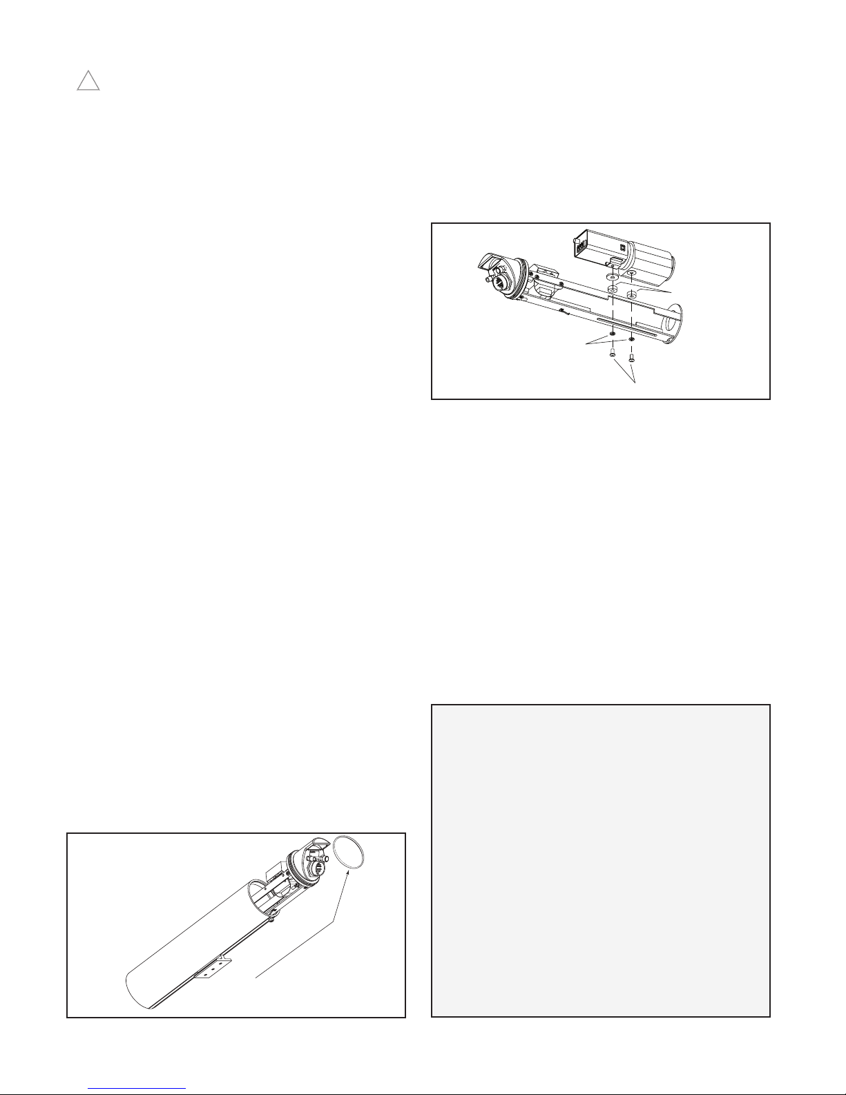
1. Remove the cradle from the housing by removing the retaining ring at the
back of the housing (Figure 1).
Retention Ring
Figure 1
WIRING
The AP16 can be used with either 115 Vac or 24 Vac power input.
TOOLS FOR USE WITH CONNECTORS
The following tools are available from
Daniels Manufacturing Corporation
6103 Anno Avenue
Orlando, FL 32809
407-855-6161
Crimp Tool: AF8 (M22520/1-01)
Crimp Tool Turret: THIA (M22520/1-02)
Insertion Tool: MS24256A16
Removal Tool: MS24256R16
The following tools are available from
Amphenol Corpl
40-60 Delaware Ave.
Sidney, NY 13838-1395
607-563-5011
Insertion Tool: M81969/17-04
Removal Tool: M81969/19-08
Page 5
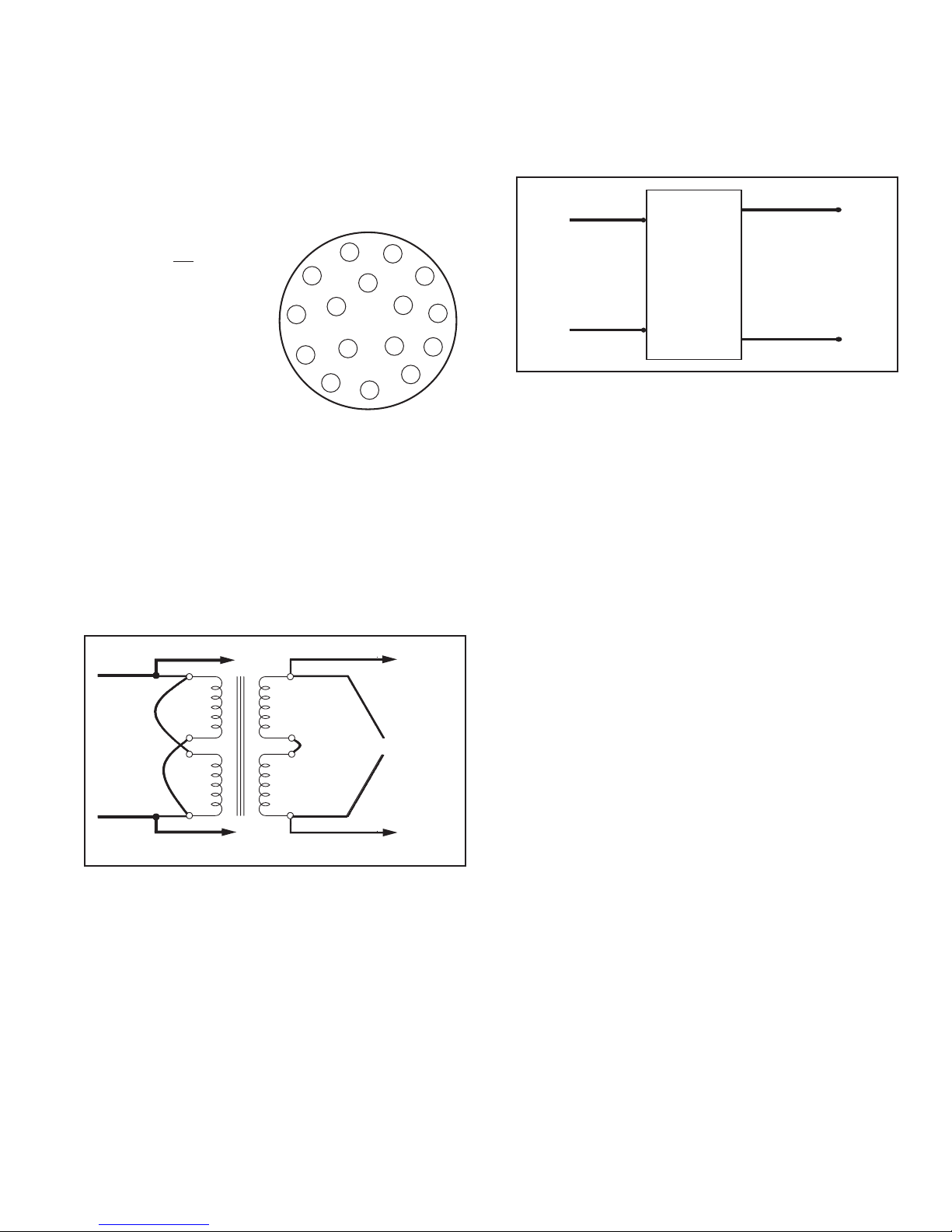
CORROSION RESISTANT CONNECTOR
All electrical connections are made via the single corrosion resistant
connector on the rear panel. A mating connector and crimp pins are supplied.
The pins will accept wire from a minimum of 0.5 mm2 (20 AWG) to a
maximum of 1.5 mm2 (16 AWG). Crimp the wire to the connector using an
appropriate crimp tool. Information on sync and video hookups is given in the
basic camera instructions.
24 Vac VERSION
The 24 Vac version is a non-transformer unit (Figure 6).
1. Connect the supply (24 Vac) to the corrosion resistant connector using
appropriate connectors. Refer to Figure 4 at left.
2. Connect power leads out of the corrosion resistant connector to the
camera (white/black striped wires).
115 Vac VERSION
Figure 3
D - Focus (BLUE)
F - Video Shield
G - Video Center
Conductor (RG59)
}
J - Earth Ground (GREEN)
K - AC Neutral (WHITE)
L - AC Hot (BLACK)
P - Zoom (RED)
R - Len Common (BROWN)
115 Vac Input, 24 Vac Camera
J
RG59-18/6cond Control Cable
L
K
S
R
H
G
(Wire Side)
Mate Connector
A
M
F
B
N
C
P
D
E
The 115 Vac version uses an internal transformer (Figure 3).
1. Connect the supply (115 Vac) to the primary ying leads of the transformer
(white wire/pin 1, black wire/pin 6). Use the wire nuts provided for this
connection.
2. Connect the secondary ying leads (white/black striped wires/pins 7 and 12)
to the camera’s 24 volt input
To Camera
Black
115 VAC
Input
White
Figure 5
To Camera
.
To Heater/Defogger
Red
6
5
2
1
12
White/
Black
Striped
11
24 VAC
8
White/
Black
7
Striped
To Heater/Defogger
Camera
Red
Black
24 VAC
Input
Pressurized
White/Black
24 VAC
Camera
Connector
White
Figure 6
PRESSURIZATION
CAUTION:
one atmosphere. Refer servicing to qualied service personnel. The
housing is tted with a standard Schrader valve to allow pressurization
with dry nitrogen to 5 lb PSI nominal at one atmosphere. An over
pressurization safety relief valve is mounted on the rear cap along
with the Schrader valve. The purpose of the relief valve is to provide a
safety pressure blow off should internal pressure exceed 140 kPa (20
PSIG) at one atmosphere. A pressurization warning label is visible on
the back of housing.
1. Place cradle into housing and push cradle forward until it is against
front lens.
2. Tighten phillips screw at the top of the housing until screw is against
housing.
3. Tighten retaining screw located at the bottom of housing.
4. Adjust cradle to desired position.
5. Add 10psi nitrogen.
6. Connect housing to power.
Pressurized container. DO NOT exceed 70kPa (10 PSIG) at
White/Black
Page 6
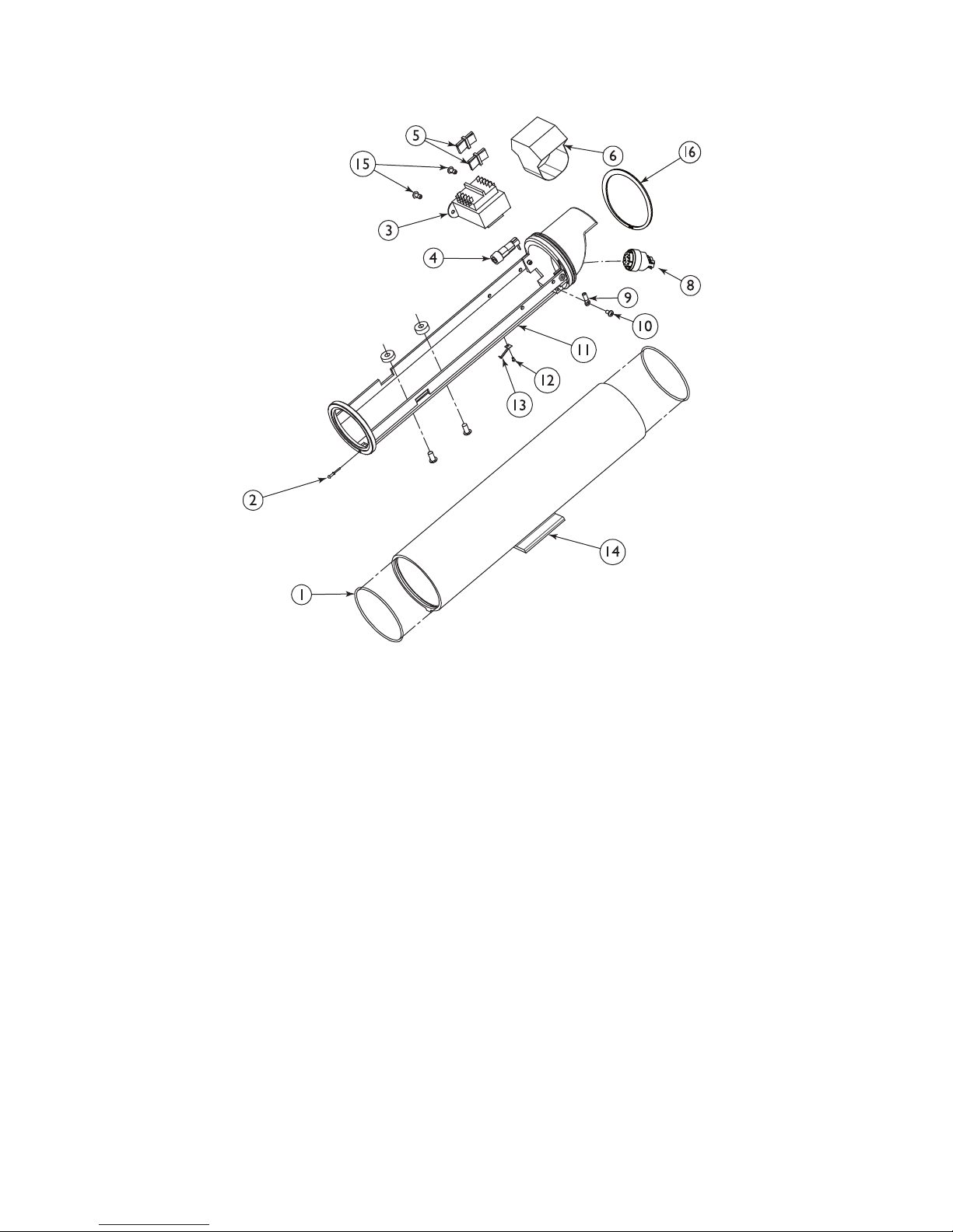
EXPLODED VIEW
Ref. No. Part Number Qty. Part Description
Connector Kit
8 315 1592-001 1 16-Pin matching connector kit
Cradle Assembly Kit – 315 3803-001
11 - 1 Cradle/Heater Assembly
16 - 1 Retaining Ring
9 - 1 Ring Tongue Terminal
13 - 1 Ground Slide
10 - 1 M4 Phillips Head Screw
12 - 1 XXX Philips Head Screw
2 - 1 Pull Seal
115 Vac Prewired Transformer Kit – 315 3804-001
3 315 3808-001 1 115 Vac Prewired Transformer
15 - 2 Rivet, 5⁄16-inch
6 - 1 Transformer Insulator
Housing Kit – 315 3807-001
14 - 1 Housing
1 - 2 Silicone O-ring
Page 7
Product Registration/Warranty
Thank you for choosing Moog Videolarm. We value your patronage and are solely committed to providing you with the highest
quality products available and superior customer service.
Should a problem arise, rest assured that Moog Videolarm stands behind its products by offering impressive 3 Year and 5 Year warranties, depending on the product
purchased. See full warranty details at www.moogvideolarm.com/technical-support/warranty-plan/
Register Your Products Online
Please take a few moments to register your purchase via the Online Product Registration Form at:
www.moogvideolarm.com/technical-support/product-registration
Register your recent Moog Videolarm purchase and benet from the following:
• Simple and Trouble-Free RMA process
• Receive product updates, and special promotion
• Eliminate the need to archive original purchase documents:
Receipts, Purchase Orders, etc…
 Loading...