

Moog Videolarm 81-IN5310 RH7CS Rugged Dome Product Instructions
81-IN5310 RH7CS Rugged Dome
Series with unitized pan/tilt/zoom
REVISION DATE: May 3, 2004
PRODUCT INSTRUCTIONS
TABLE OF CONTENTS
Description 1
Electrical Specifi cations 1
Parts List 1
Installing Quick Release Bracket 1
Installing the Housing Assembly 1
Installing Optional Pendant Mount 2
Wiring Color Code Chart 3
Wiring Distance Chart 3
Setting the Protocol 3
Setting the Address 3
Optional VLPT385 Settings 4
Pan/Tilt Address Dip Switch Settings 5
Exploded Views 8
Mounting Template 10
Safeguards and Warranty Info 11
NOTE: This unit is designed for operation in an upright
position. Installing the RH7 upside down may
cause damage to the internal equipment, and
will void the warranty.
DESCRIPTION:
The vandal resistant RH7CS Housing top is high impact resistant
cast aluminum; the lower dome is made of an optically clear, UV
stable, polycarbonate plastic. It measures 9.75” (w) x 13 (h) x 14.5”
(d) with a weight of 8.25 lbs. Flying leads are provided for all power,
control and video connections, with a standard BNC and (2) screw
down connectors. Two 25W heater (50 watts total) with (2) circulation
fans are also supplied.
ELECTRICAL SPECIFICATIONS (OUTDOOR ONLY):
Power 24VAC, Class 2 Only
!
GENERAL INSTRUCTIONS:
Tools Required: .100" Flat Head Screwdriver
Phillips Head Screwdriver
Be sure the bracket is properly and securely mounted
to a supporting structure capable of rigidly holding the
!
weight of the entire unit.
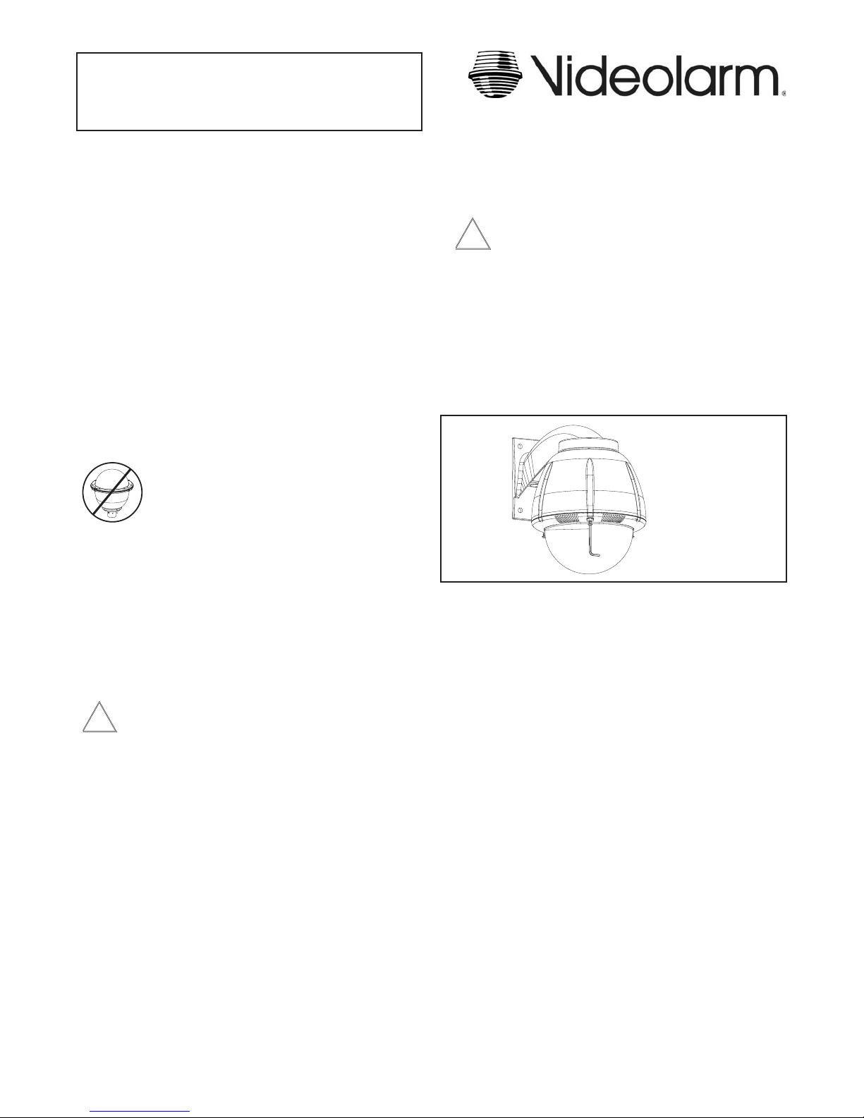
INSTALLING QUICK RELEASE BRACKET AND
PAN/TILT CAMERA ASSEMBLY (ALL MODELS)
1. Open the housing by loosening the (3) tamper proof screws
located on the housing ring next to the lower clear dome
(Figure 1). Be careful not to back these all the way out. Twist the
dome slightly in a counterclockwise motion until it stops, then pull
down to remove.
Loosen screws only,
do not remove
Remove dome by
twisting coun ter clock wise until it
Figure 1
2. Install the pan/tilt unit quick- release bracket. It is recommended
that this be done before installing the housing. On the next
page are instructions for mounting quick-release brackets from
selected manufacturers.
3. Clean the inside of the dome. Reattach the housing dome and
secure the (3) captive screws. Do not overtighten the screws.
Tighten only to the point at which the gap between the ring and
the housing top closes.
stops, then pull down
52 watts at 24 VAC (accessories)
Heater: 50 watts
Blower: 2 watts
Input Connectors (outdoor units):
BNC, (2) screw-down connectors
PA RTS LIST
Check to be sure the following parts are included in the box:
1. Housing
2. Housing Packet
a. (2) Mates for screw down connectors (not supplied with
indoor units)
b. (1) Adapter plate
c. (8) 1/2" standoffs
d. (8) 8 x 32 x 3/8" Mounting screws with star washers
e. (3) 6 x 32 x 3/8" Mounting screws with star washers
f. (2) 1/4 x 20 x 3/8" HH Bolts
g. (2) 1/4” Flat washers
h. (2) 1/4" Split Lock washers
i. Instruction Manual
INSTALLING THE HOUSING ASSEMBLY
FOR WALL MOUNT, RH7CS
1. RH7CS
A wall mount bracket comes standard with this unit, and a tem-
plate is included to use as a guide for mounting the bracket to a
wall. Choose the desired location for installation and mark the drill
holes using the template. Screw (2) bolts (not provided) about 3/4
of the way into the (2) top holes. Run approximately 8" of wiring
out of the wall.
NOTE: Be sure the hardware and the mounting surface can sup-
port the weight of the wall mount bracket plus the weight
of the housing and drive unit. The load will be subjected
to vibration from the camera motor and wind.
- 1 -
2. The wall mount bracket provided with the rugged housing includes
a location for conduit entry. If you wish to install conduit to the
bracket remove the conduit hole plug. Install fi tting from below the
wall mount and secure with conduit nut from inside the bracket.
3. Open the access door on the bottom of the wall mount by
loosening the screw nearest the mounting plate (Figure 2).
Twist and
Secure
Access
Door
Figure 2
4. Attach the wires from the wall to the connector provided, using the
wiring color code chart as a guide.
5. Once all wiring connections are made, place the wires inside the
wall mount bracket and close the access door. Secure with the
screw removed earlier.
6. Clean the outside of the dome.
FOR OPTIONAL PENDANT MOUNT
1. This unit includes a 1 1/2" NPT housing for a standard 1 1/2" NPT
pipe. The RH7CS can be used with other brackets designed with
1 1/2" male pipe threads, such as the Videolarm WM20G and
WM20 wall mount brackets.
2. Attach the housing coupling (Figure 3).
NOTE: Pipe threads should be clean and rust free. Use a
sealer (such as Tefl on™ tape or silicone sealer) on the
threads.
Figure 4
5. Clean the outside of the dome.
The RH7CS is setup with (2) individual power inputs.
1. Accessory Power (yellow and green wire)
2. Camera Power (red and orange)
If you wish to provide a single power transformer it is recommended
that:
1. Be certain that you know the total power consumption of the hous-
ing Heaters (50 watts) + Blowers (2 watts) + camera/pan-tilt (not
supplied)
2. Check the supplied wiring chart to be sure that you have the
proper gauge wire for the distance that you intend to run your
power wires.
3. Bring power to the 3 and 4 position of the power connector (yellow
and green wire)
4. Two jumpers are provided in the housing packet. Jumper from the
st
1
position to the 3rd position and from the 2nd position to the 4th
position of the terminal block. Be careful not to short between the
yellow and green wires.
Add thread
sealing tape
Figure 3
3. Mount the housing assembly to the mounting bracket and housing
coupling. A safety cable is included with the housing to
temporarily hold it while making wiring connections. Loop the
safety cable over one of the set screws on the housing coupling
and make the appropriate connections using the (2) screw-down
connectors supplied.
4. Undo the safety cable and twist the housing onto the housing
coupling. Secure all (3) setscrews provided on the housing
coupling (Figure 4).
Add 2 jumpers for
single power input
Figure 5
- 2 -
MOUNTING THE HOUSING
1. Mount the housing assembly to the mounting bracket and
housing coupling. A safety cable is included to temporarily hold it
while making wiring connections. Loop the safety cable over one
of the set screws on the coupling and make the appropriate con-
nections using the 14 position circular and BNC connectors.
Wiring Color Code
Power and Control Inputs
(Outside of housing)
POWER
1 Camera Power (24 VAC) Red
2 Camera Power (24 VAC) Orange
3 Accessory Power (24 VAC) Yellow
4 Accessory Power (24 VAC) Green
CONTROL
1 RS-485RXA Blue
2 RS-485RXB Violet
3 RS-485TXA Gray
4 RS-485TXB White
Power and Control Outputs
(Inside of housing)
POWER AND CONTROL LEADS
1 Camera Power (24 VAC) Red
2 Camera Power (24 VAC) Orange
3 RS-485RXA Blue
4 RS-485RXB Violet
5 RS-485TXA Gray
6 RS-485TXB White
24k VAC Wiring Distances
The following are the recommended maximum distances for 24 VAC
with a 10% voltage drop (10% is generally the maximum allowable
voltage drop for AC powered devices).
Wire Gauge
Total vA
consumed
5.5
10
20
30
40
50
60
70
80
90
100
110
120
130
140
150
160
170
180
190
200
22
250
120
89
65
44
35
29
25
31
19
17
16
14
13
12
11
11
10
9
9
8
20
400
180
141
90
70
56
47
40
34
31
28
25
23
21
20
18
17
16
15
14
14
18
600
300
225
130
112
90
75
64
55
50
45
41
37
34
32
30
28
26
25
23
22
16
960
480
358
225
179
143
119
102
85
79
71
65
59
55
51
47
44
42
39
37
35
14
-
800
571
350
285
228
190
163
140
126
114
103
95
87
81
76
71
67
63
60
57
12
-
1300
905
525
452
362
301
258
215
201
181
164
150
139
129
120
113
106
100
95
90
10
-
-
1440
830
720
576
480
411
340
320
288
261
240
221
205
192
180
169
160
151
144
SETTING PROTOCOL FOR THE UNIT
Different protocols can be used for the pan/tilt, with the default set for
Videolarm/Cohu protocol. Protocol is set using the four dip switches
located on the PC Board on the side of the unit (Figure 4).
PROTOCOL SETTINGS
SW4 SW3 SW2 SW1
Videolarm/Cohu off off off off
Pelco P off off off on
Kalatel off off on on
Sensormatic off on off off
Protocol
Dip Switches
Figure 4
SETTING THE ADDRESS FOR THE UNIT
Each pan/tilt must have its own unique address. The factory
default address is 001 . To change this address use the 8 position
dip switch located on the PC Board on the side of the pan/tilt (Figure
4), referring to the chart in the back of this manual. The address is set
with the rocker style dip switches, which are non-volatile. The address
cannot be changed unless the dip switches are moved, or unless the
Remote Address featue in the test sofware is used.
INSTALLING THE PAN/TILT
1. Place the two posts on the pan/tilt into the holes on the mount
bracket inside the housing. Secure the Safety fastener located on
the other side of the pan tilt (Figure 3).
Maximum distance from transformer to load
SECURE FASTENER
Figure 3
Address
Dip Switches
PC Board
located here
- 3 -

OPTIONAL SETTINGS FOR THE VLPT385
On Screen Display
To enter On Screen Display, go to preset 10 on COHU controller, or
go to preset 57 on Videolarm controller. “DISPLAY” should be visible in
the top left corner of the screen and the pan and tilt functions will not
control the motion of the pan/tilt.
Use “tilt up” or “tilt down” to navigate up or down along the main menu.
Use “pan right” and “pan left” to select between the main menu selection
and the sub menu. The “zoom in” and “zoom out” are used to turn the
selected functions on or off.
SHUTTER - The shutter function is used to select between automatic
shutter speed and one of 12 manual shutter speeds. To
get to this submenu, tilt down from the AUTOIR menu.
Tilt up or down to select the desired shutter setting. The
selections are:
AUTO, 2(1/2), 4(1/4), 8(1/8), 15(1/15), 30(1/30),
60(1/60), 90(1/90), 100(1/100), 125(1/125), 180(1/180),
250(1/250), 350(1/350), 500(1/500), 725(1/750),
1000(1/1000), 1500(1/1500), 2000(1/2000),
3000(1/3000), 4000(1/4000), 6000(1/6000),
10000(1/10000).
To exit this submenu, pan left.
DISPLAY
This controls the display of the compass heading and allows the user
to calibrate the compass heading.
COMPASS - To access the compass display, pan right. The display
should show “COMPASS ON” or “COMPASS OFF”. To
change the status of the compass display, press “zoom
in” to turn the compass heading on and “zoom out’ to
turn the compass display off.
NORTH - To calibrate the compass heading, pan right from the
“DISPLAY” menu to the “COMPASS” display and then
tilt down to access the “NORTH” display. Press the
“zoom in” button to set calibration. The display should
show “OK”.
POSITION - This displays the pan and tilt positions of the camera on
the bottom of the screen. Tilt down from the “NORTH”
display to access this submenu.
To e xit the “COMPASS” or “NORTH” displays, pan left to the “DISPLAY”
menu. This should bring up the “CAMERA” display.
CAMERA
The “CAMERA” menu is used to control several of the camera’s parameters. To access the “CAMERA” menu, tilt down from the “DISPLAY”
menu, then pan right.
STABLITY - stability function. To access this menu, pan right from the
“CAMERA” menu. The stability function compensates for
small movements or vibrations when the camera is
“zoomed in”. The screen should show either “STABLE
ON” or “STABLE OFF”. The stability function can be
turned off by pressing the zoom out button or turned on
by pressing the zoom in button. To exit this submenu,
pan left
AUTOIR - This is used to control the low light mode of the camera.
With the AUTOIR on, in low light conditions the camera
will switch into black and white mode and remove the
infrared cut fi lter from the optical path. With the AUTOIR
off, the camera will not switch into the low light mode.
Tilt down from the STABILITY submenu to access this
sub menu. The screen should show either “AUTOIR ON”
or “AUTO OFF”. The AUTOIR function can be turned off
by pressing the zoom out button or turned on by press-
ing the zoom in button. To exit this submenu, pan left.
ALARM
To get to this section, tilt down from the CAMERA menu. This menu
allows the user to control the operation of the alarm input. If the alarm
is enabled, the camera will go to preset 1 on the COHU controller or
preset 47 on the Videolarm controller when the alarm is activated.
ENABLE To change the setting of the alarm enable, pan right
from the ALARM menu and press zoom in to enable
the alarm or press zoom out to disable the alarm. ). To
exit this submenu, pan left.
ZONES
To get to this section, tilt down from the ALARM menu. There are 16
zones that may be selected, each zone has a number of parameters
associated with it. To access a specifi c zone, fi rst pan right to get to the
“ZONE 1” display. Use the tilt up and tilt down to select a specifi c zone;
each zone number will displayed as selected. When the desired zone
is displayed, do a pan right to get to the individual zone parameters for
that zone. All settings are stored in non-volatile memory.
SHOW This parameter controls whether or not the zone title is
to be displayed at the bottom of the screen. Press the
zoom in button to set this to on, and use the zoom out
button to set the zone display off.
PRIVATE This parameter determines if the zone is to be a
privacy zone. Press the zoom in button to set this to on,
and use the zoom out button to set the zone privacy off.
RLIMIT This sets the pan right limit for the zone. Press the
zoom out button to enable the pan motion, the RLIMIT
display should fl ash. Position the camera at the right
pan limit for the zone. Press the zoom in button to set
the position or press the zoom out button to go back to
menu mode without setting the limit.
LLIMIT This sets the pan left limit for the zone. Press the zoom
out button to enable the pan motion, the LLIMIT display
should fl ash. Position the camera at the left pan limit for
the zone. Press the zoom in button to set the position or
press the zoom out button to go back to menu mode
without setting the limit.
SET TITLE This is used to set the title of the zone. To change the
zone title, tilt down. The current zone title will be
displayed at the bottom of the screen with at
question mark (?) at the cursor position. Use pan right
or left to change the cursor position. When the desired
position has been selected, use tilt up and tilt down to
- 4 -
 Loading...