

Page 1
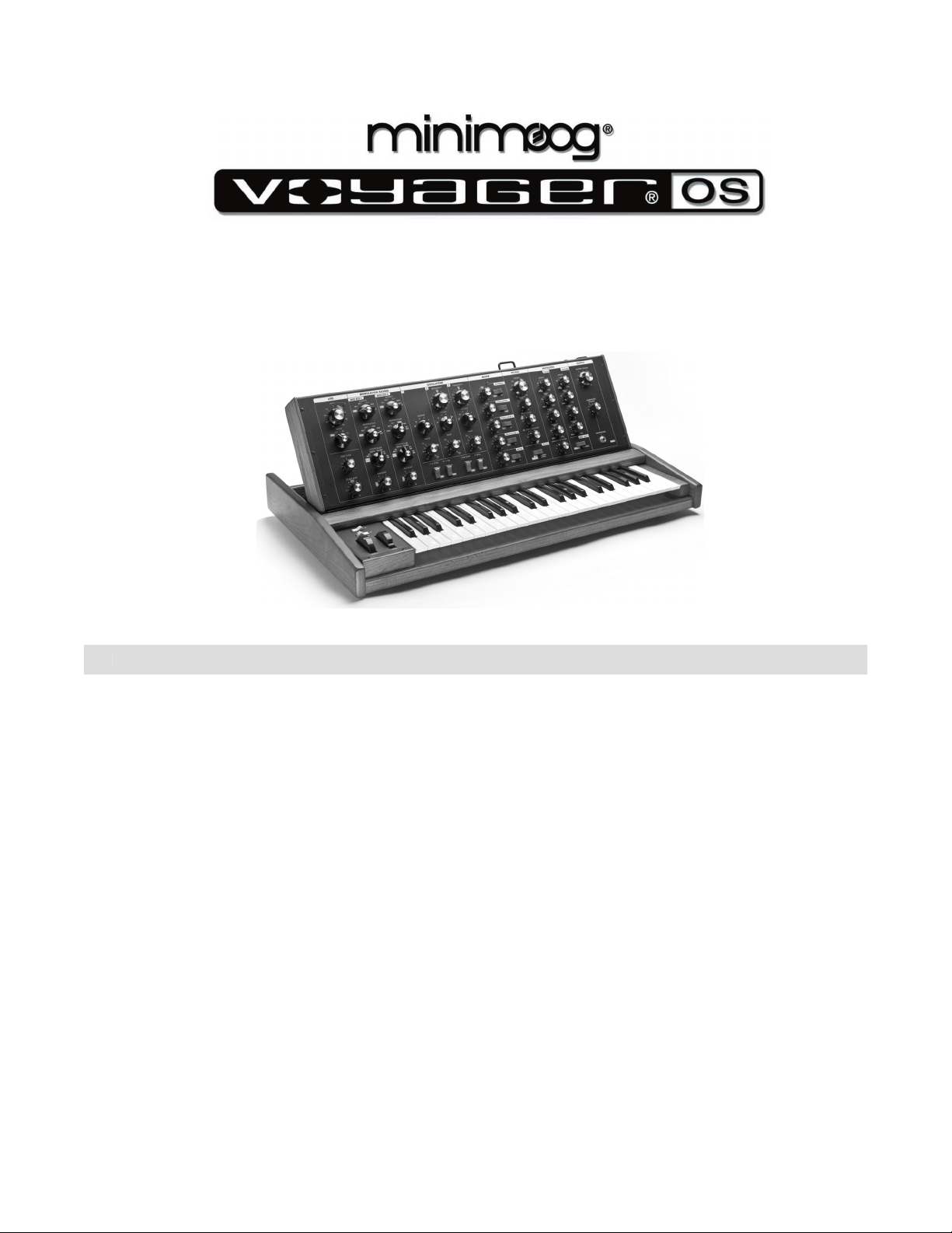
Table of Contents
THE BASICS
5
6
8
THE COMPONENTS
A. Mixer Section ........................................................
APPENDICES
A – Speci cations .................................................................
Page 3
Page 2
And, if you are ever near Asheville, N.C. USA, please come by the Moog factory. We’d love to see you!
Warm Regards,
Page 4
Page 3
Voyager OS User’s Manual - The Basics
This User’s Manual is organized into convenient sections to assist you in setting up, playing and exploring
your new Voyager OS.
The
section explains how to unpack, setup and connect the Voyager OS, and provides
The
section offers detailed explanations of the Voyager OS components that create and modify
The
Appendix
provides additional information, such as technical speci cations, service and suppor t info, and
At the back of the manual, you’ll nd a
that de nes important synthesizer terminology, and several
pages for programming and documenting your favorite sounds.
Throughout the manual you will see icons that offer additional information. Here’s what they mean:
This icon indicates an important note concerning the operation of the Voyager.
This icon indicates a useful performance or programming tip.
This icon indicates technical information for the advanced user or the technically curious.
Page 5
Page 4
Voyager OS User’s Manual - The Basics
Page 7
Voyager OS User’s Manual - The Basics
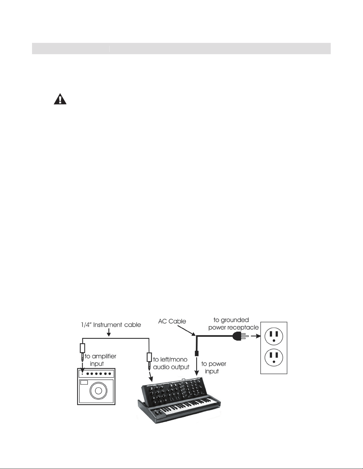
The Voyager is shipped with the following items:
What you will need
that will provide the proper support (the Voyager Old School weighs approximately 40 lbs.) and will not
The Voyager’s universal power supply will operate with
Page 6
Page 5

Voyager OS User’s Manual - The Basics
Turn the Voyager OS power ON. The LFO RATE LED will be begin to blink at the rate set by LFO RATE
volume to a comfortable listening level.
The sound produced by the Voyager OS is determined by the various knob and switch settings on the front
To create your own sounds from scratch, it’s best to start from a default patch con guration. This will give
you a familiar starting point and guaranty that sound will be produced. To set the Voyager OS to a default
you a basic one-oscillator square wave sound that will act as a blank canvas for your sonic creations.
After you adjust the Voyager panel controls to the default settings, try the controls to the right of the Mixer,
and
to see
When working with the Voyager, keep in mind that many of the controls are interactive, so there is
frequently more than one way to control a single parameter. This may be a source of confusion at rst.
control of the
Volume Envelope
is all the way down, and the
ATTACK
and
knobs are set to zero, there will be no output. Similarly, if you have a sound where the
AMOUNT
knob for the
is set to zero, then changing the Filter Envelope
ATTACK
control
will likely result in no audible change. To use your Voyager to its fullest potential, it is very important to
Warranty registration
web site at www.moogmusic.com and click on the “Product Register” tab. If you complete all the requested
Voyager. The warm up period may be longer if the Voyager has been stored outside the recom-
Page 7
Page 6
Voyager OS User’s Manual - The Basics
Page 9
Voyager OS User’s Manual - The Basics
The Voyager OS is a monophonic analog performance synthesizer that is a successor to the classic Model D
Page 8
Page 7
Voyager OS User’s Manual - The Basics
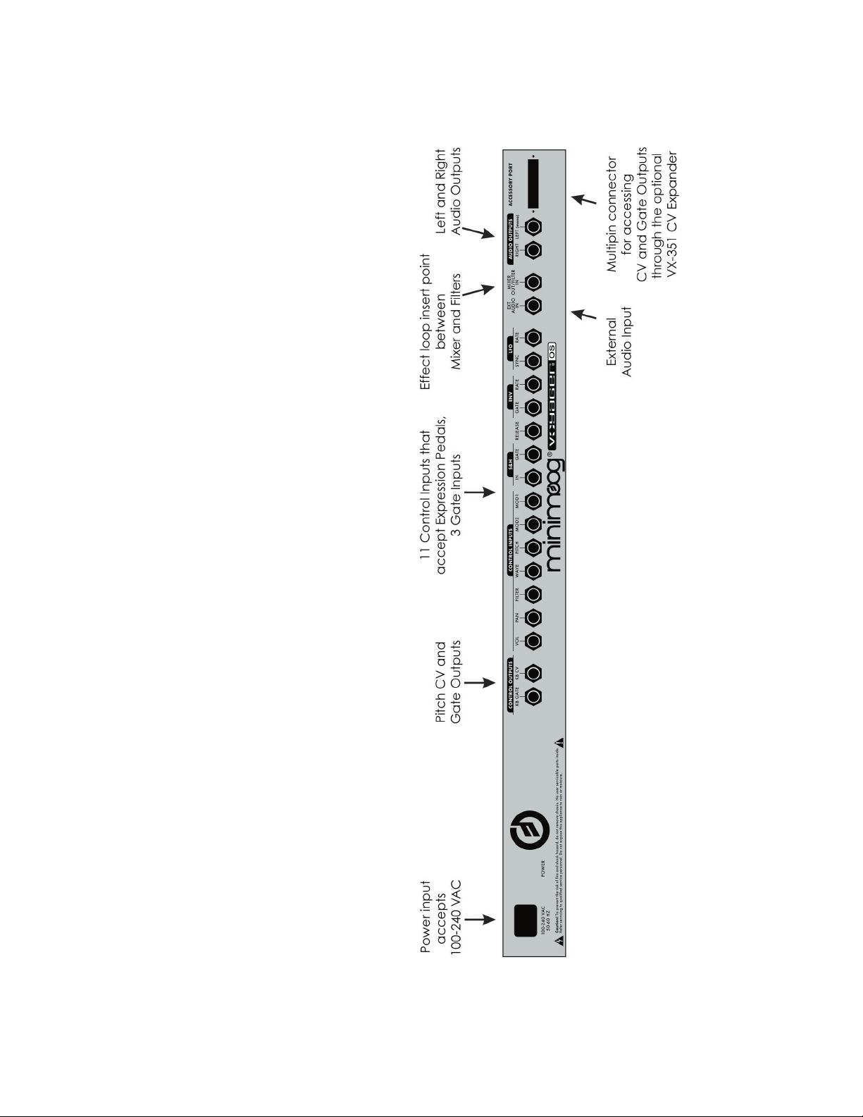
The Voyager’s back panel offers con-
There are 14 CV inputs and 2 CV out-
tion CV/Expression Pedal input, while
jacks identi ed with a blue nut indicate
Page 9
Page 8
Voyager OS User’s Manual - The Basics
Page 11
Voyager OS User’s Manual - The Basics
To understand the signal ow of the Voyager OS, it’s helpful to consider the three types of signal rout-
Audio Path
The Voyager’s audio path includes all of the signal sources and signal modi ers that produce an audio
The Oscillator section includes controls for selecting the octave and waveforms, adjusting the tuning of
the second and third oscillators, for setting the oscillator sync and linear FM functions, and for setting the
frequency range and keyboard control for Oscillator 3.
The Mixer section is where the oscillators and other sound sources (noise and external input) are
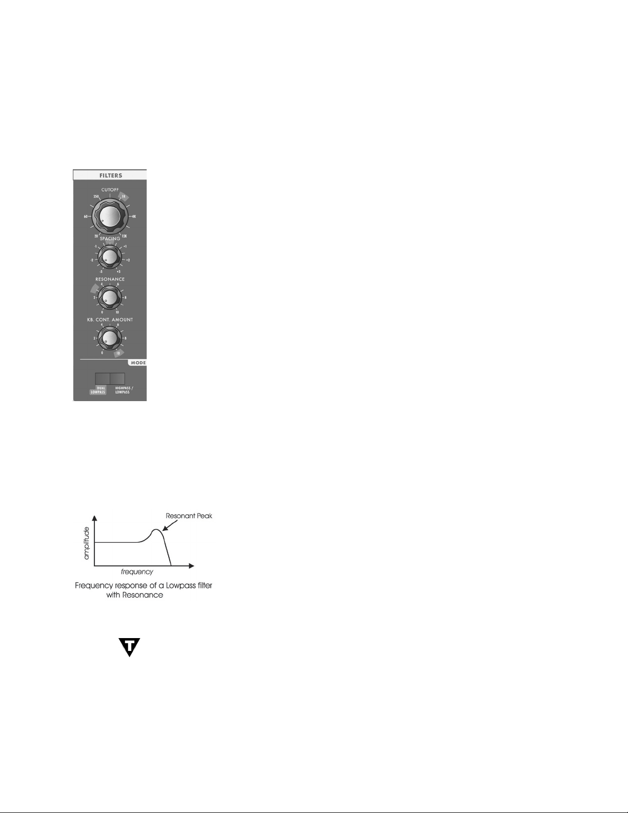
The Filter section is responsible for altering the harmonic content of the combined sound sources. The
Voyager’s Filter section contains two lters that work together in two different modes.: Dual LP and
features a lowpass and highpass lter in series, creating a Bandpass lter response. In either mode, the
the difference between the cutoff frequencies. The outputs of the lters are routed to the Voltage
The VCAs shape the volume level of the audio signal using time-varying control signals called Envelopes.
The Envelopes section (part of the control voltage path) contains one Envelope Generator to control
the Filters, and one Envelope Generator to control the VCAs. The Voyager’s audio path is illustrated
The Voyager OS Audio Path
Page 10
Page 9
Voyager OS User’s Manual - The Basics
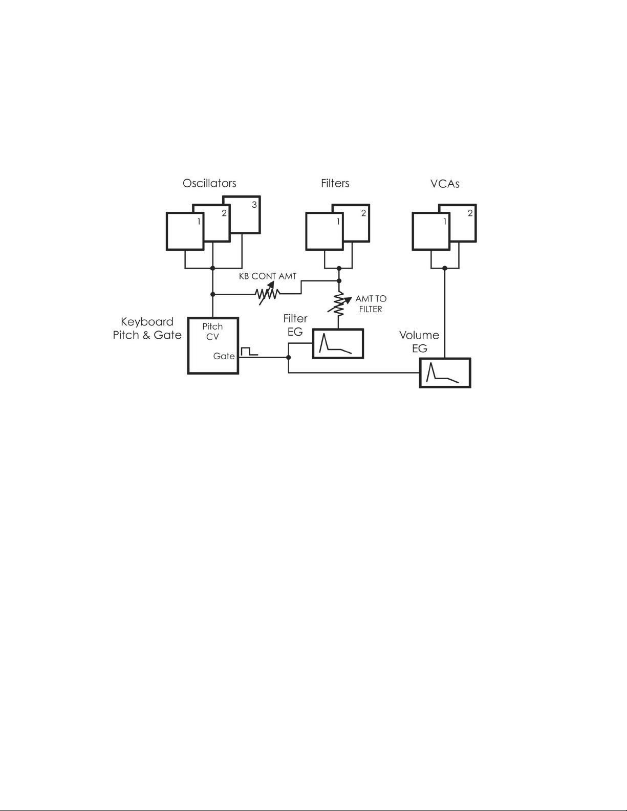
When a key is pressed, a Gate and Pitch Control Voltage (CV) are produced. The Gate signal is used to
trigger both the Filter and Volume Envelope Generators (EGs). The Pitch CV is used to determine the
Amount knob. The basic control voltage path is illustrated below.
The Voyager OS Control Voltage Path
Page 11
Page 10

Voyager OS User’s Manual - The Basics
The Voyager OS Modulation Buss
Page 12
Page 11
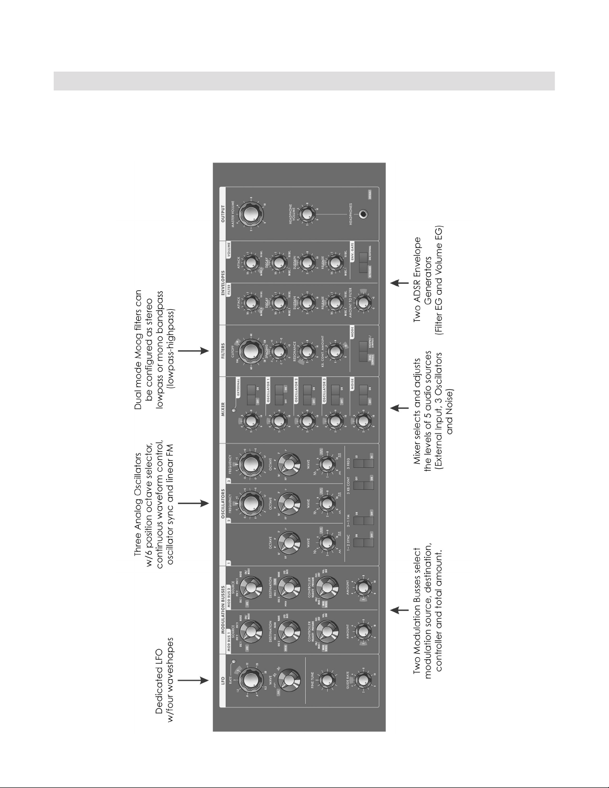
Voyager OS User’s Manual - The Components
with the Mixer section. Then we’ll cover the Oscillators, Filters, Envelopes, and Output Sections, the LFO and
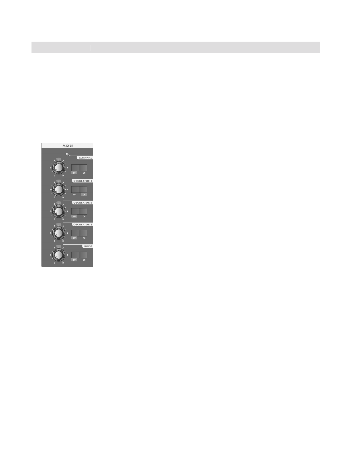
A. The Mixer Section
The Mixer combines the main sound sources of the Voyager. It’s a good place to start when creating a new
The ve sound sources are:
The audio output of the Mixer is routed to the Filter through an insert jack on the
Voyager’s back panel. If an inser t cable is plugged into this jack, the Mixer output can
for more information).
The
controls in the Mixer allow each oscillator to be switched ON or OFF, and mixed
The
control is used to mix noise with the other sound sources. The Voyager’s Noise source is
wind noise component to traditional instrument emulations, or for adding subtle coloration to a sound.
Page 13
Page 12

Voyager OS User’s Manual - The Components
Page 15
Voyager OS User’s Manual - The Components
The
The jack on the back labeled “Mix Out/Filter In” is an insert point between the Mixer output and the Filter
to the ring of the jack. A cable fully plugged into the jack breaks the connection between the Mixer and the
As always, experimentation is encouraged!
Page 14
Page 13
Voyager OS User’s Manual - The Components
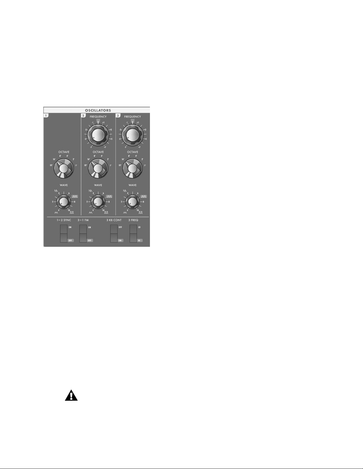
The Oscillators are the main sound source of the Voyager. The oscillators in the Voyager are all analog
Voltage Controlled Oscillators, or VCOs. They feature a temperature regulation circuit that provides them
with excellent tuning stability. The VCOs can produce a total musical range of 8 octaves! In addition, the
frequency of oscillator 3 can be set to the sub-audio range (<20Hz) for use as a second LFO.
there are switches for Oscillator 2 sync to Oscillator 1;
The frequencies of the Oscillators are controlled by a number
the Keyboard CV and the oscillators to slow the changes
Tune control, and the output of the Mod Busses when the
switch that selects the relative frequency range. To hear how it
works, turn off Oscillators 2 and 3 in the Mixer. Switch Oscillator 1 ON and set its level to 5. Play a note
You can use this control to change the frequency range that the keyboard controls. The panel markings
from 32’ up to 1’ are octave standards based on organ stops.
control. When the control is in the center position, the oscillators
Page 15
Page 14
Voyager OS User’s Manual - The Components
Page 17
Voyager OS User’s Manual - The Components
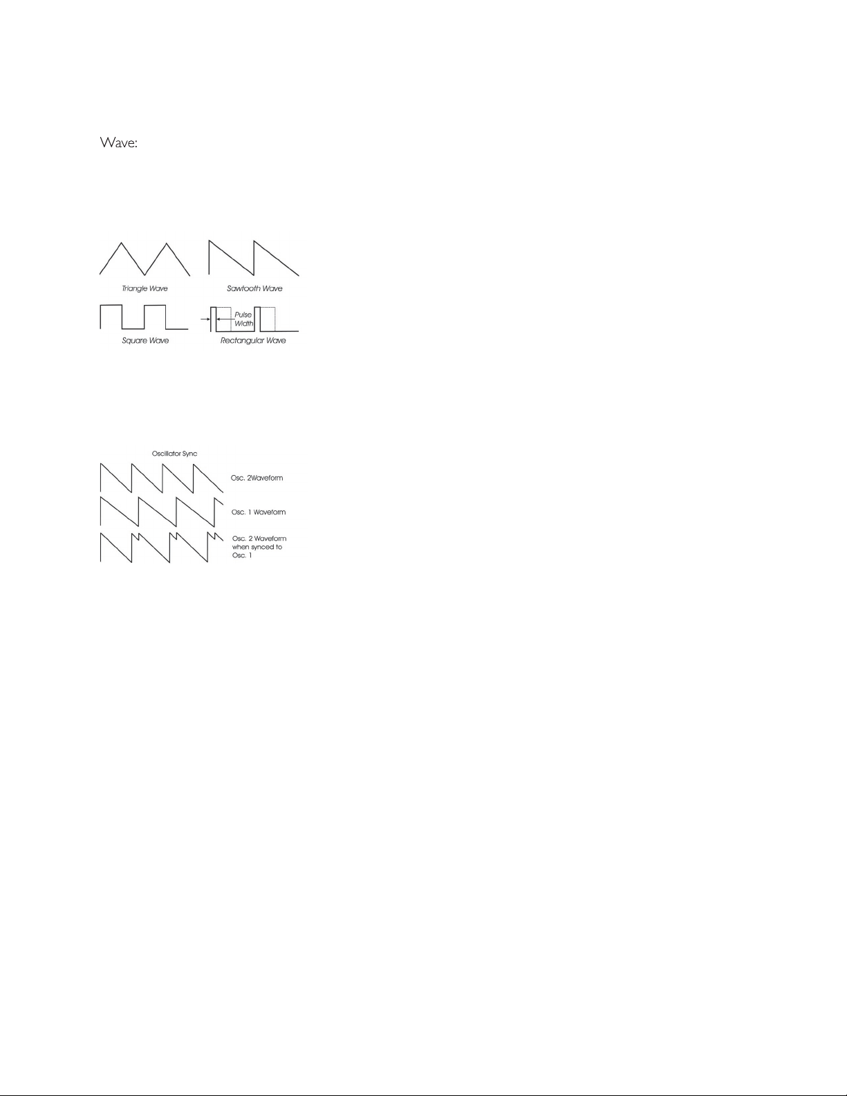
Wave:
WAVE
(waveform) control. The legend on the front panel
WAVE
control is rotated.
the square and rectangular waveform, you can get pulse width
front panel individually for each oscillator, modulation through the
The
switch is one of four switches located at the bottom of the oscillator panel. In the ON
1-2 SYNC
switch synchronizes Oscillator 2 to Oscillator 1. Oscillator sync is an effect caused
frequency heard is that of the reset oscillator. As the frequency
when Oscillator 2 is set to a higher octave than Oscillator 1.
The
3 KB CONT
switch disables keyboard control of Oscillator 3 when in the OFF position. By disabling
the keyboard control, you can use Oscillator 3 as a drone or as a modulation source whose frequency
to OFF increases the amount by which the Oscillator
control changes the frequency of
The
switch selects the frequency range of Oscillator 3. When the switch is in the LO position,
When the switch is in the HI position, Oscillator 3 operates with the same available frequency range as
Page 16
Page 15
Voyager OS User’s Manual - The Components
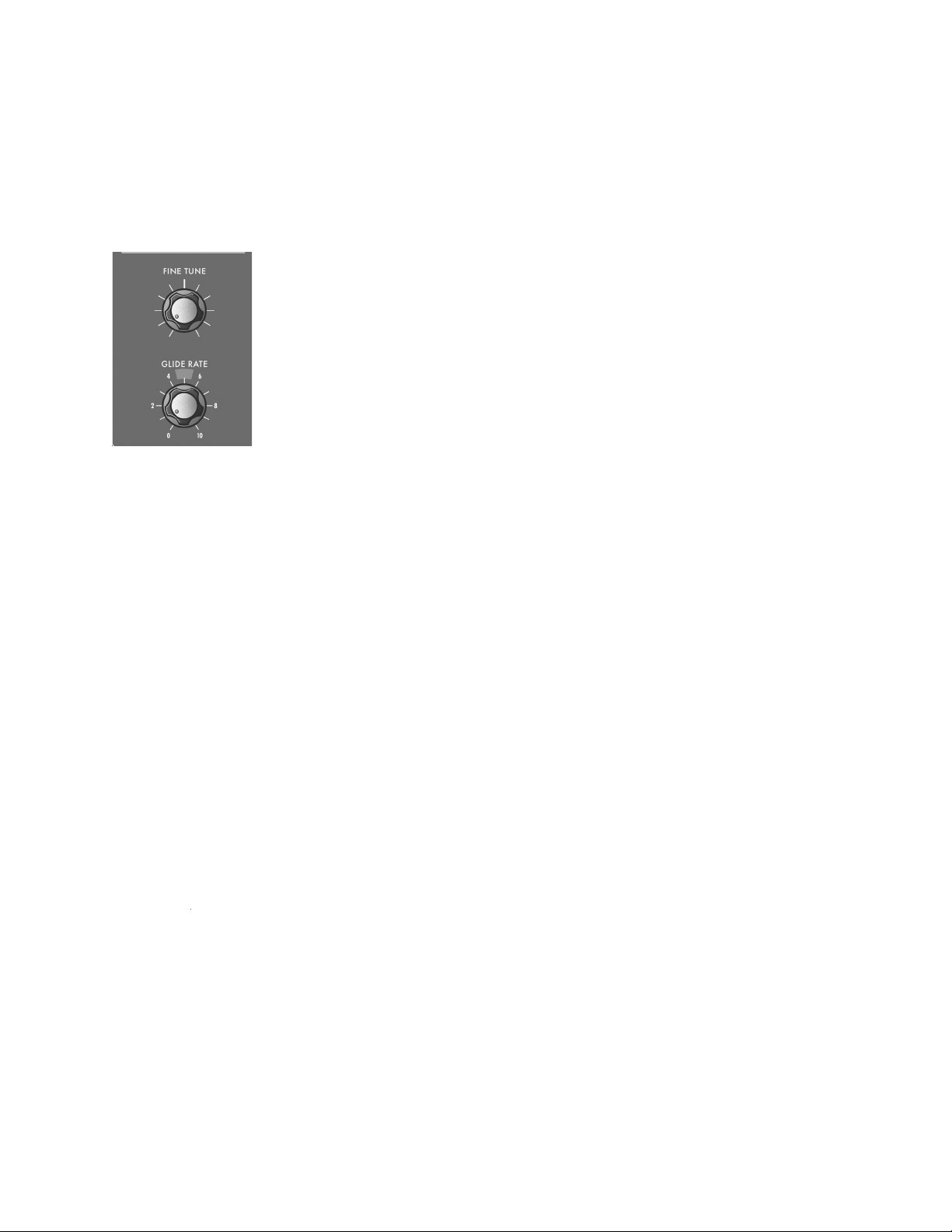
Two other panel controls interact with the Voyager Oscillators: Fine Tune and Glide
The
FINE TUNE
control is used to tune the Voyager’s oscillators +/ – 2 semitones
for matching an external reference pitch.
the rate of the glissando. The glide rate can vary from a very fast to a very slow
switch in the Voyager keyboard left-
Additional CV Connections (Input)
The
jack allows you to connect an external CV or expression pedal to control the Voyager’s pitch.
All three oscillators are effected by this connection. The effective input range is -5 to +5V, where a positive
voltage).
Wave:
The
WAVE
jack allows you to connect an external CV or expression pedal to control the oscillator wave-
forms. All three oscillators are effected by this connection. The effective input range is 0 to +5V, resulting in
WAVE
dial panel setting, making it
to force the width of the rectangular wave so skinny that it becomes silent.
Additional CV Connections (Output)
The
jack outputs the keyboard pitch control voltage, allowing you to control external CV gear. The
The
jack outputs a gate trigger signal every time a key is pressed. The Gate signal is a +5V trigger
that can be used to trigger external envelope generators, sequencers, or other sources.
Page 17
Page 16
Voyager OS User’s Manual - The Components
Page 19
Voyager OS User’s Manual - The Components
frequencies while allowing others to pass through. To understand the operation of lters and how they
vibe of the original hardware.
The rst is ‘Cutoff Frequency’. The cutoff frequency is the point at which an audio
frequencies below the cutoff frequency and rejects frequencies above the cutoff. A
the lowpass section de nes the maximum frequency that will pass through, while the
Another key lter term is the ‘Cutoff Slope’. The cutoff slope determines the amount
The last lter term to consider is ‘Resonance’. Resonance refers to a peak that appears at the cutoff
frequency. In synthesizers, this resonant peak is usually an adjustable parameter (called ‘ Resonance’ ) that
the sound being ltered, those overtones are reinforced. This gives the
the lters’ cutoff frequencies track the keyboard note that is played. As
you play higher on the keyboard, the cutoff frequency goes higher, too.
Page 18
Page 17
Voyager OS User’s Manual - The Components
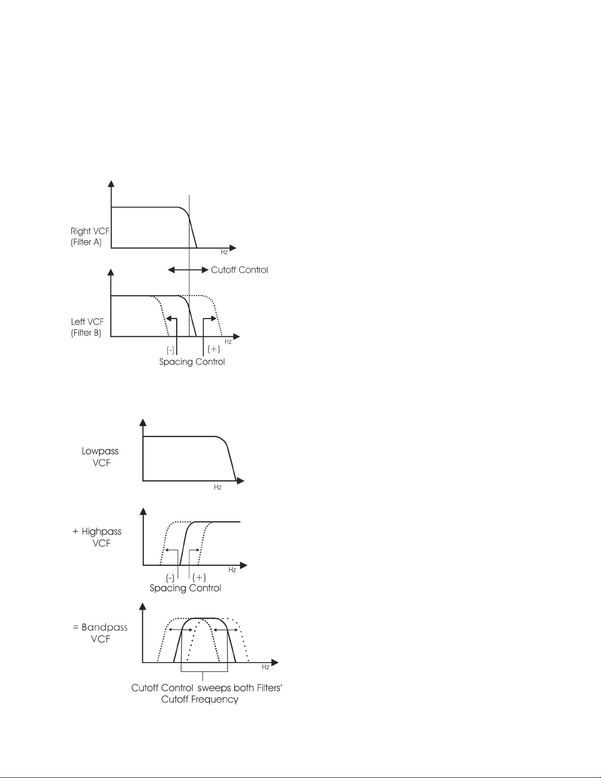
The Voyager’s Dual Lowpass mode provides two
The
knob controls the frequency cutoff of
frequency, or adjusted to different cutoff frequencies
control. When the two lters are
RESONANCE
control affects
the Dual Lowpass mode, the
control changes
the cutoff frequency of both lters, and the
the two lters creates a variable passband. In this mode,
the
RESONANCE
control affects only the Lowpass
The Voyager has two voltage controlled lters (VCF’s) that can be con gured either as dual lowpass lters
Page 19
Page 18

Voyager OS User’s Manual - The Components
Page 21
Voyager OS User’s Manual - The Components
The
knob is the main lter control. This sets the cutoff frequency of both lters in Dual Lowpass
through the lter. This is why as you turn the control clockwise the cutoff frequency becomes higher and
the sound becomes brighter. Of course, to hear the effect of a lowpass lter it helps to have a signal rich
control changes the center frequency of the passband.
The
control is used to determine the difference between the cutoff frequencies of the two lters
control knob is centered, the cutoff frequencies of the two
control to +1 in
control
control is swept, two resonant peaks are heard, giving the lter a unique quality.
control sets the difference between the cutoff frequencies by
control is fully clockwise, the
The
RESONANCE
control causes feedback in the lter circuit that adds harmonic emphasis at the cutoff
frequency. This control affects the Lowpass lter(s) in either lter mode, but not the Highpass lter. When
the
control is all the way down, the lowpass lters act as a tone control, rolling off the high
control is turned down. As the resonance increases, the lter begins to form
control is
turned up the peak increases in strength until the control is set to about 8 or higher, where it begins to self-
The
KEYBOARD CONTROL AMOUNT
knob allows the lter cutoff to follow the key played on the
Voyager keyboard. A higher key will cause a higher cutoff frequency. This allows a sound to retain its
The lter
switch selects either the Dual Lowpass con guration (DUAL LP) or the Highpass/Lowpass
Page 20
Page 19

Voyager OS User’s Manual - The Components
When triggered, EG’s produce a time-varying control voltage that has a
this pro le are Attack, Decay, Sustain and Release, sometimes abbrevi-
Attack determines the character of the onset of the sound. The EG’s
ATTACK
knob controls this parameter by adjusting the time it takes
for the envelope to go from zero to full value (in other words, the
fade-in time). The
control adjusts the second stage in the
to drop from the full level to the level set by the
control.
The envelope will remain at the Sustain level as long as an envelope
control determines the time it takes for the en-
velope to transition from the Sustain level to zero (refer to the ADSR
The Voyager has two identical EG circuits; one EG is dedicated to the
the ampli er (to control the volume). Both EG’s can also be used as
Additional CV Connections
The
jack allows you to connect an external CV or expression pedal to control the lter cutoff
frequency. Both lters are effected by this connection, regardless of the lter mode setting. The effective
Page 21
Page 20

Voyager OS User’s Manual - The Components
Page 23
Voyager OS User’s Manual - The Components
Attack:
The
ATTACK
control sets the attack time of the corresponding envelope generator, from 1 msec to 10
The
control sets the decay time of the corresponding envelope generator, from 1 msec to 10
The
control sets the corresponding level for the sustained part of the envelope.
The
control sets the release time of the corresponding envelope (the time for the envelope
to transition from the sustain level to zero), from 1 msec to 10 seconds.
Amount To Filter:
AMOUNT TO FILTER
control that adjusts the amount of the lter
AMOUNT TO FILTER
control has both positive and
dial
dial setting.
When the gate is off, the Release portion of the envelope is executed as shown below. The switch
KEYB/ ON/EXT
selects whether the envelopes are triggered from the keyboard, or from
(Keyboard) triggering is selected, the envelopes are triggered by
for
(On/External), the envelope gate source defaults to ON if nothing is plugged into the
their respective
controls. This is useful for keeping the envelopes sustaining without holding
Page 22
Page 21

Voyager OS User’s Manual - The Components
The release time of the envelopes is set by their respective
control knob, but this control can also
switch located in the left-hand control
Additional CV Connections:
The
jack allows you to connect a footswitch or input a CV gate signal to remotely trigger both
switch is set to
switch is set to ‘KEYB’, any input on the
jack will be ignored.
The
jack allows you to connect a footswitch or input a CV gate signal. Pressing the footswitch
the setting of the
switch.
The
jack is a CV input for external control of the Voyager’s envelope time constants, using either a
voltage applied to the
jack will decrease the attack, decay and release times from the envelope
Page 23
Page 22

Voyager OS User’s Manual - The Components
Page 25
Voyager OS User’s Manual - The Components
The Voyager has two audio outputs. There is a Voltage Controlled Ampli er (VCA) for each output, which
the Master Volume control. The Volume Envelope Generator modulates the output VCAs.
The
knob is the main volume control. Full-clockwise is
This
knob controls the volume that appears on
the
jack. Full-clockwise is maximum output, full-
The
connection is a ” TRS jack that outputs the
Voyager signal to a pair of stereo headphones.
Additional CV Connections:
Volume:
The
VOLUME
jack allows you to connect an external CV or expression pedal to control the output
volume. Both VCA’s are effected by this connection. The effective input range is 0 to +5V, where
The
jack allows you to connect an external CV or expression pedal to control panning between
the right and left outputs. The effective input range is -5 to +5V, where -5V = Fully Left and
jack, the pedal will reach its full
jack. Note also that you will
voltage does not go below 0V.
volume of the Voyager OS
Page 24
Page 23

Voyager OS User’s Manual - The Components
The Modulation Busses allow you to select a variety of modulation
two Mod Busses are labeled MOD BUS 1 and MOD BUS 2, and
to fade in and fade out the desired modulation. If nothing is plugged
AMOUNT
control sets the total modulation amount.
The diagram below shows the con guration of a single Mod Bus, but
the controls and selections for both busses are the same.
Page 25
Page 24

Voyager OS User’s Manual - The Components
Page 27
Voyager OS User’s Manual - The Components
Two controls modify the amount of modulation sent to the destination: the selected controller (set with the
knob) and the
AMOUNT
control. When the selected controller is a performance control
the selected controller is an envelope, the modulation varies according to the envelope parameters. In both
AMOUNT
control always sets the maximum amount of modulation.
To try out a simple modulation effect, make the following settings:
control to about 6 Hz
WAVE
control to ‘LFO’
control to ‘PITCH’
selector to ‘MOD WHEEL’
AMOUNT
control to 2
These settings allow the Mod Wheel performance control to be used to fade in the modulation, which
tion Busses offer a wealth of modulation possibilities which make the Voyager OS an incredible sound
The
There are six selections available:
The
control selects the destination of the modulation. The modulation destination is cho-
Page 26
Page 25

Voyager OS User’s Manual - The Components
The
dial selects from six modulation controller options. The Controller selections are:
Wheel in the left-hand controller section.
when this is selected, the Mod Bus AMOUNT control will set the total amount of
Amount:
The
AMOUNT
control
AMOUNT
control is set to 0, no modulation will pass. When
AMOUNT
is set to
the envelopes)
Additional CV Control
The
jack
The
jack allows you to apply an external modulation source into the MOD busses. The input
control is set to ‘ON/MOD2’, the voltage applied
to this jack becomes the Modulation Source.
Page 27
Page 26

Voyager OS User’s Manual - The Components
Page 29
Voyager OS User’s Manual - The Components
The Voyager OS has a dedicated Low Frequency Oscillator (LFO). The LFO produces triangle and square
waves as well as stepped and smoothed Sample & Hold (S&H) signals over a range of approximately 0.2 to
The Voyager’s CV Interface jacks on the back panel of the Voyager allow additional
the S&H Gate input, it will disconnect the LFO trigger; an external gate signal can
then be used to trigger the S&H circuit. Similarly, a plug inserted into the S&H
when the S&H circuit is triggered, the voltage at the tip of the plug is held at the
Page 28
Page 27

Voyager OS User’s Manual - The Components
The
control sets the frequency of the LFO. The
control frequency range is approximately 0.2
to 50 Hz.
Wave:
The
WAVE
control selects the LFO waveform. There are four waveforms available:
Triangle
Additional CV Connections
The
jack accepts an expression pedal or a control voltage from -5 to +5V. A positive voltage
control.
The
jack accepts a footswitch or a +5V Gate input. Closing the footswitch or applying a gate
The
jack accepts an expression pedal or a control voltage from -5 to +5V. The voltage on this jack
The
jack accepts a +5V Gate input. Applying a gate signal here will trigger the Sample and Hold
Page 29
Page 28

Voyager OS User’s Manual - The Components
Page 31
Voyager OS User’s Manual - The Components
The Voyager OS has a 44-note keyboard (3 octaves,
These voltages can be used as modulation
VX-351 CV Expander.
To the left of the keyboard is the Left Hand Controller Panel,
which contains the Pitch Bend and Mod Wheel performance
The Voyager OS keyboard priority is LAST NOTE, and the trigger mode is LEGATO. ‘Last Note’ means that
tion of notes on the keyboard is held down, the keyboard Gate signal is high (in other words, Single Trigger
Trigger mode the next time the unit is powered up unless the top two keys of the keyboard are held down.
This spring-loaded performance control affects the pitch of all three oscillators.
The pitch bend amount is
The Pitch Bend amount is set by an internal jumper. Although most players will be comfortable
with the factory default setting (+/-5 semitones), wider or narrower ranges can be set by recon guring
This performance control adjusts the amount of modulation that is sent to the modulation destination when
the Mod Buss
The
switch turns the Glide function ON and OFF. The glide rate is controlled by the
The
switch is used to shorten the release time of both the Filter and Volume envelopes. You will
switch is
Page 30
Page 29

Voyager OS User’s Manual - The Components
The
and
outputs on the Voyager OS are unbalanced ” TS jacks for use with
When just the
output is connected, both channels are summed to this output. A stereo
and
outputs are used. When the Voyager Filter is set
to ‘Dual Lowpass Mode’, the
output can be used to get a monophonic sound that is unaffected by
the Filter’s
control.
This is an unbalanced ” TS input that accepts any instrument or line level signal and routes the signal to
the Mixer. A dedicated
input control on the Mixer adjusts the signal level.
This is a ” TRS jack that is used for inserting a processing device between the Voyager’s Mixer and Filters.
The tip is the send and the ring is the return (see the illustration on page 14).
The CV/Expression Inputs are ” TS jacks color coded with a red nut. These jacks accept an input from
– Do not alter the power connector in any way. Doing so can
The back panel provides for all of the Voyager’s connectivity, including power, audio and CV expansion con-
This is a standard AC power inlet. Use only a power cord designed to mate with this receptacle. The
Voyager power supply is designed to work with power inputs of 100-240 VAC; 50-60 Hz.
Page 31
Page 30

Voyager OS User’s Manual - The Components
The Gate/Footswitch Inputs are ” TS jacks color coded with a blue nut. These jacks accept an input from
Accessory Port:
The Voyager OS has a DB-25 connector which connects to the optional VX-351 Voyager CV Expander.
This device outputs all the CV and Gate signals that are generated by the Voyager on ” jacks. For more
will trigger the envelopes. Make sure that the Volume Envelope SUSTAIN control is set to
CV Output:
The Keyboard Pitch CV (labeled ‘KB CV’) is available at this output. This CV is scaled to 1V/octave. The
actual voltage corresponds to the last note played on the keyboard.
Gate Output:
The Keyboard Gate (labeled ‘KB GATE’) is available at this output. This signal is a +5V trigger signal that is
generated with each key press.
Page 32
Page 31

Voyager OS User’s Manual - Appendices
Appendix A - Speci cations
form control, 1 Noise source, 5-input Mixer,
Transmits monophonic velocity and after-
touch control voltages
(range is internally adjustable)
AC Power Inlet (universal power supply,
that allow external control of
various CV and Gate functions)
Accessory Output Port (DB25 connector)
for optional VX-351 CV Expander
jacks on
TRS jack on
front panel. Dedicated Headphone
Volume control.
Weight:
Page 33
Page 32

Voyager OS User’s Manual - Appendices
Page 35
Voyager OS User’s Manual - Appendices
Appendix B - VX-351 CV Expander
were known as modular synthesizers, because each function of the synthesizer was contained in a single
was not without its drawbacks, however, which include:
Time – creating sounds from scratch takes a lot of practice, patience, and time.
templates, and, due to its smaller size and weight, the synth can actually be carried to gigs without having to
front panel, the Voyager OS offers even more functions than the original Minimoog, and provides expansion
full advantage of this capability, you need a way to access all of the Voyager’s control voltage signals, both
The VX-351 Voyager CV Expander is an add-on product that expands
your Voyager OS into a semi-modular synth. The VX-351 contains
on ” jacks (19 CV outputs
for reducing or inverting the strength of a CV signal, and two 4-way
Page 34
Page 33

Voyager OS User’s Manual - Appendices
To connect the VX-351, locate the male end (the end with recessed pins) of the DB-25 cable - this
Align the cable properly and make the connection. Use the thumbscrews to lock the connection.
ACCESSORY PORT”.
Voyager’s
control will change the rate that the Filter Cutoff moves up and down. This
the VX-351 Attenuators. Set the Attenuator amount to zero. Using another ” cable, make a
the Destination.
This is a very basic use for the VX-351, but it demonstrates the fundamental concept of how to use it:
Page 35
Page 34

Voyager OS User’s Manual - Appendices
Page 37
Voyager OS User’s Manual - Appendices
VX-351 CV Output Expander - Description
The following is a description of the outputs and functions contained in the VX-351 CV Output Expander.
TOUCH
This group of four outputs is not used with the Voyager OS.
This group of outputs is generated from the Voyager’s Keyboard. There are three control voltages (Pitch,
Velocity and Pressure) and one gate signal.
VEL:
This is the CV determined by the velocity used to press a key.
This is the CV determined by how much pressure is exerted on a key after it is pressed.
This is the gate signal generated when a key is pressed.
WHEELS
This group of outputs is generated from the Voyager keyboard’s Left Hand Controller Wheels.
This is the CV generated from the Mod Wheel.
This group of outputs is generated from the MOD1 and MOD2 jacks on the rear panel of the Voyager.
that determines how much of the PEDAL/ON Mod Bus Source goes to the PEDAL/ON Mod
Volt signal at the MOD1Input. The Voltage that appears at the MOD1 Input is duplicated at the
Voyager that is an external modulation source for the Mod Busses. With nothing plugged into
the MOD2 jack, the voltage that’s present at the MOD2 jack is +5V. When a CV is plugged
that appears at the MOD2 Input is duplicated at the MOD2 output.
This group of outputs is generated from the Voyager’s LFO. There are two CV waveforms available here
TRIANGLE: This is the triangle wave output of the LFO.
Page 36
Page 35

Voyager OS User’s Manual - Appendices
This group of outputs is generated by the Mod Buss signals. They are the Modulation source after being
WHEEL: This is the output of the Mod Wheel Mod Buss. It is the Mod Wheel SOURCE shaped by the
AMOUNT
control and the MOD WHEEL.
AMOUNT
control and the signal at the
This group of outputs is the output of the Envelope Generators.
VOLUME: This is the CV output of the Volume Envelope Generator.
This group of outputs is generated by the Sample and Hold Circuit.
ATTENUATORS
The VX-351 contains two attenuators. An attenuator is used to reduce the amount of a CV signal. The
The VX-351 contains two 4-way Multiples, or ‘Mults’. A Mult is used to distribute a single source to multiple
this case, all three of those parameters will be controlled simultaneously by the LFO.
use a CV mixer (like the
Page 37
Page 36

Voyager OS User’s Manual - Appendices
Page 39
Voyager OS User’s Manual - Appendices
TOUCH
Y
A
VEL
WHEELS
TRIANGLE
WHEEL (Note 4)
VOLUME
The table below shows the effective ranges of the VX-351 Outputs.
VX-351 CV Expander Outputs
Page 38
Page 37

Voyager OS User’s Manual - Appendices
VX-351 CV OUTPUT EXPANDER
Vol Env
Atten 1/Amount
Atten 2/Amount
A list of the Expander connections (like the one shown below) is a convenient way to document CV
on the VX-351 are not used. These jacks are omitted on the above list.
Page 39
Page 38

Voyager OS User’s Manual - Appendices
Page 41
Voyager OS User’s Manual - Appendices
The following are some simple ways to use the VX-351 with the Voyager OS. Gather up some ” patch
This will con gure the Mod Wheel as a volume controller. Perform the following steps:
AMOUNT:
Voyager’s VOLUME jack.
to 60 (about 9 o’clock) and turn the
GLIDE
and
theremin-like patch where the volume and timbre is completely controlled by your left hand
while you play the notes with your right hand.
This is an alternative to triggering a sound from the Voyager by pressing a key. In this example, the last key
you press will determine the pitch, but the LFO will continuously trigger the star t of the envelopes.
Voyager’s Envelope Gate (ENV GATE) Input.
switch to ‘ON/EXTERNAL’. You should immediately
control while you tweak
the
and Envelope controls.
Attenuator.
WAVE jack.
Page 40
Page 39

Voyager OS User’s Manual - Appendices
The Moogerfooger® CP-251 Control Processor makes an ideal
two waveforms (Triangle/Square), a Sample & Hold circuit with two
Voyager, so the CP-251 and VX-351 add an extra level of modulation
The LFO in the CP-251 can be used for common modulations such as vibrato, tremolo, auto-pan and
To try any of the examples shown below, begin by connecting the CP-251’s LFO Triangle output to an At-
tenuator Input, then follow the example to complete the modulation routing.
To create Vibrato:
jack. On the CP-251, set the LFO
control to 6 Hz (about 1 o’clock), and adjust the
ATTEN-
control to about ‘0.5’ on the dial (a very low amount). This con guration will produce a
control considerably higher will result in wild
To create Tremolo:
VOLUME jack. On the CP-251, set the LFO
ATTENUATOR
control to ‘10’ on the dial. This will produce a constant tremolo effect. Adjust the
To produce Auto-Panning:
jack. On the CP-251, set the LFO
control to ‘10’ on the dial. This will produce a constant panning effect. Adjust the LFO
Appendix C - Using the CP-251 with the Voyager
Page 41
Page 40

Voyager OS User’s Manual - Appendices
Page 43
Voyager OS User’s Manual - Appendices
To produce a modulated lter effect:
control to 6 Hz (about 1 o’clock), and adjust the
ATTENUATOR
to about ‘2’ on the dial. This will produce a cyclical tonal variation as the lter cutoff
frequency is modulated. Setting the CP-251’s LFO
control considerably higher will result in
wild timbral textures, while a very low setting will create a slowly evolving lter sweep.
This is a handy little trick that can be used to lower the lter cutoff as you play higher on the keyboard. This
control to ‘0’
ATTENUATOR
control level to -5.
and
ATTENUATOR
controls to taste.
A Sample and Hold circuit can be used for more than generating random voltages. One type of modulation
wave into discreet voltage levels that resembles a staircase. We’ll use two LFO’s for this; a slow one for the
Voyager’s Sample and Hold Input jack (S&H IN).
control to about 6 Hz (about 1 o’ clock on the dial).
the Voyager’s Sample and Hold Gate Input jack (S&H GATE).
WAVE
AMOUNT:
Page 42
Page 41

Voyager OS User’s Manual - Appendices
from the Mult to the Mixer 1 & Mixer 2 inputs. Set the Mixer 1 & 2, and Master levels to
We’ve covered some basic uses of the Voyager and the VX-351 and CP-251. Other CV compatible
analog effects can be incorporated to further expand the sonic palette.
With all of the control options provided, the possibilities for sound creation are nearly limitless!
We’ve just scratched the Surface
The examples provided here are just a few of the synthesis possibilities afforded by the Voyager OS and our
you should always connect a source to a destination, and that you shouldn’t combine multiple source CVs
without a mixer. We encourage you to experiment, as there are many possibilities for exploring synthesis
– whether you are trying to duplicate a sound or effect you heard, or if you are trying to make a sound that
Page 43
Page 42

Voyager OS User’s Manual - Appendices
Page 45
Voyager OS User’s Manual - Appendices
Appendix D - SynthesisTutorial
the low end) to about 20,000 Hz (on the high end). The frequency of
A second perception of sound is its volume or loudness. Loud sounds
Amplitude, which is measured in Decibels (dB).
A third perception of sound is its tone color, also known as its timbre. There is no standard of measurement
for timbre, so instead we use familiar terms to describe the tone color of a sound – bright or dull, buzzy or
they decrease as the frequency goes up, so a 200hz harmonic will be louder than a 300Hz harmonic, which
will be louder than a 400Hz harmonic, and so on. Note that there are some sounds that contain overtones
that are not mathematically related to the base pitch. These include the ‘metallic’ sounds created by percus-
timbre) to create new sounds and simulate existing ones. This process is called Synthesis. There are a
to achieve the desired sound.
A synthesizer design based on subtractive synthesis typically consists of three main components and three
Page 44
Page 43

Voyager OS User’s Manual - Appendices
The Oscillator is the starting point of Subtractive Synthesis, for it is here that the initial sound is created. The
The pitch of the oscillator is primarily determined by the keyboard, which creates speci c pitches based on an
The waveform determines the harmonic richness of the audio signal. There are four basic waveforms common
to most synthesizers: sawtooth, square, triangle and sine.
The sawtooth wave is the richest sounding of the four waves. It contains all
for brass and string sounds, bass sounds and rich accompaniments.
The square wave possesses a hollow sound compared to the sawtooth,
An interesting aspect of the square wave is that the waveshape can be
wave. By changing the shape of the wave, new harmonics are introduced.
for creating lush pads. Many synthesizers allow you to dynamically control
the shape, or ‘width’ of the pulse wave using modulation sources such as a
The Subtractive Synthesis Model
Page 45
Page 44

Voyager OS User’s Manual - Appendices
Page 47
Voyager OS User’s Manual - Appendices
triangle wave has a soft, slightly buzzy sound that is suitable for high-
The sine wave is the purest waveform of them all. It has no harmonics,
waveform and level (volume) parameters. Several oscillators make possible rich and complex sound source
to combine them with the oscillators, or process the external audio by itself using the synthesizer compo-
The combined sound sources are routed to the Filter, a circuit that removes or reduces frequencies (and
A Lowpass lter gets its name because it allows low frequencies to pass
through while removing or reducing the high frequencies. The point
to the lter’s ‘slope’, which is a measure of how well the lter works.
The slope of a lter is expressed in decibels per octave (dB/Oct). The
Voyager lter is rated at 24 dB/Oct, which creates a dramatic reduction
Another important lter parameter is the lter resonance. Resonance ampli es the frequencies at the
The Filtered signal is routed to the Ampli er, which controls the gain (volume) of the signal. The Ampli-
The Oscillator, Filter and Ampli er are voltage controlled, meaning that they respond to changes in voltages.
voltage, the higher the cutoff frequency. For the Ampli er, this means the higher the voltage, the greater the
volume. Since each of the three main components respond to a voltage, the entire synthesis system thus
further vary the sound.
Page 46
Page 45

Voyager OS User’s Manual - Appendices
whenever a key is pressed. The level of the control voltage signal is a function of which key is pressed - the
The keyboard’s control voltage signal is commonly routed to the oscillators to control the pitch, and it can also
trigger signal is routed to the Envelope Generators to trigger the envelopes.
The second
auxiliary component is the Envelope Generator, or EG. The
voltage that is typically used to control the gain of the ampli er, or the
The EG is triggered from a Gate signal that is generated every time a
The Voyager’s Envelope Generators have four stages that can be set individually:
Attack – The time to go from zero volts to the maximum voltage (the fade in time).
The last auxiliary component to mention is the Low Frequency Oscillator,
typically used to send modulation control signals to the main components.
vibrato by varying the pitch of the oscillator. If you send that same LFO
variations in the sound, making the sound more dynamic and interesting.
Page 47
Page 46

Voyager OS User’s Manual - Appendices
Page 49
Voyager OS User’s Manual - Appendices
two extensive modulation sections, and the Voyager’s third oscillator can act as an additional LFO. As you
would expect, synthesizers that offer more than one of each component provide a broader palette for
worth of explanations and examples. For tunately, a number of excellent books have been written on the
As with all musical instruments, practice, exploration and experimentation are an important par t of achiev-
Page 48
Page 47

Voyager OS User’s Manual - Appendices
Appendix E - Service and Support Information
tory basis. This warranty covers defects that Moog Music determines are no fault of the user. In countries
for service.
You must obtain prior approval in the form of an RMA (Return Material Authorization) number from Moog
What we will do
transport. If the product has been abused, damaged in transit, or is out of warranty, we will contact you with
you do not have web access, ll out the all the information on the included warranty card and mail to:
Attn: New Product Registration
Asheville, N.C. USA 28804
Appendix F - Caring for the Voyager Old School
Voyager’s wood casing can be cleaned with a guitar polish, or a ne furniture polish. Heed the safety warnings at
the beginning of the manual. Don’t drop the unit. If you are shipping your Voyager to the factory for servicing,
we recommend using the original shipping carton, or an ATA approved Road Case. Shipping the Voyager in a
AN IMPORTANT NOTE ABOUT SAFETY: Do not open the chassis. There are no user
Page 49
Page 48

Voyager OS User’s Manual - Appendices
Page 51
Voyager OS User’s Manual - Appendices
To further enhance the functionality and appearance of the Minimoog Voyager OS, Moog Music offers the
following optional accessories. For complete information on everything listed here, including pricing and
The EP2 Expression Pedal is the nest expression pedal available. Its smooth action gives it the feel
VX-351 CV Expander
The VX-351 Voyager CV Expander provides all the CV and Gate outputs of the Voyager OS on standard ”
The CP-251 Control Voltage Processor offers a number CV processing options that can be used with any
Voyager, Moogerfooger analog effects module, or other voltage-controlled gear. The CP-251 provides a dual
waveform LFO, Noise Generator, Sample-and-Hold circuit, as well as two active attenuators, a Lag Processor,
voltages to produce the incredible variety of sounds and effects that analog synthesizers are famous for.
VX-351 Rack Mount Kit
The VX-351 Rack Mount Kit allows you to mount any combination of two CV Expanders or CV Processors
The FS-1 Footswitch is a heavy-duty footswitch in a steel enclosure. The switch is a momentary, normally
with a ” mono phone plug attached.
touring schedules.
Appendix G - Accessories
Page 50
Page 49

Voyager OS User’s Manual - Appendices
Accessories (Con’t)
Voyager Gig Bag
Voyager. The gig bag is made of heavy-duty nylon material, with double-stitched construction and a pouch
for your cables and accessories.
Voyager Extended Warranty (available to US customers only)
The Extended Warranty adds three years to the Voyager’s standard one-year warranty, providing you a total
Page 51
Page 50

Voyager OS User’s Manual - Glossary
Page 53
Voyager User’s Manual - Glossary
ADSR – Abbreviation for Attack, Decay, Sustain and Release, the four stages of an envelope control voltage
Amplitude – The strength of a sound’s vibration measured in Decibels (dB). Amplitude corresponds to the
the CV, the higher the gain, or volume).
volume) over time. For example, when a string is plucked, its amplitude is suddenly very loud, but then
the plucked sound is very bright, but then the brightness fades away. This describes the Tonal envelope
tone) and ampli ers (affecting volume).
varying signal that can be applied to any voltage-controlled circuit. The Envelope Generators in the
Voyager have four adjustable segments: Attack, Decay, Sustain and Release, also sometimes referred to as
ADSR. The Attack, Decay and Release segments are speci ed as time parameters, while the Sustain seg-
ADSR envelope. This trigger is called a gate signal, and it’s produced whenever a key is pressed on the
the gate signal turns off. When the gate is on, the Envelope Generator is triggered and the envelope
.
Page 52
Page 51

Voyager User’s Manual - Glossary
A lter has a cutoff frequency that determines the point at which frequencies begin to be removed. A
frequency are removed and frequencies above the cutoff are passed through. A bandpass lter has two
two terms are not always interchangeable. Frequency is an objective measurement of a sound, while pitch
while the other oscillator is known as the ‘carrier’. The carrier oscillator is the one you hear. When
the modulator frequency is very low (about 6Hz), the effect is described as vibrato. As the modulator
frequency is raised into the audio range, new modulation frequency components are created, and the effect
the harmonic series. These sounds are typically pleasing to the ear and generally the consecutive vibrations
which the harmonics are not mathematically related. Their waveforms look chaotic. White noise is an
the pitch of a VCO, results in vibrato. Changing the LFO waveform to a square wave will result in a trill.
An LFO modulating a VCA with a triangle wave creates tremolo.
Page 53
Page 52

Voyager OS User’s Manual - Glossary
Page 55
Voyager User’s Manual - Glossary
frequency is determined by one or more control voltages. Changes to these voltages correspond to
time a trigger or gate signal is received. Sample and hold circuits commonly employ white noise as a signal
taken. Since the signal source is noise (a random audio signal), the output of the S&H circuit is also random.
The sampling interval is typically controlled by a low frequency oscillator (LFO). By adjusting the speed
Page 54
Page 53

Voyager User’s Manual - Glossary
Timbre – Pronounced ‘tamber’, it refers to the quality of a sound by its overtones. An unprocessed sawtooth
wave has a bright timbre, while a triangle wave has a mellow timbre.
Tremolo – Technically a form of low frequency amplitude modulation, tremolo is a smooth audible pulsing of
volume. In synthesizers, tremolo is produced when a 5-6Hz LFO triangle or sine wave signal is applied to a
voltage controlled ampli er.
Waveform – The shape of an oscillator’s vibration. This shape determines its timbre. Commonly used
waveforms in subtractive synthesis include sawtooth, triangle, square, or rectangular. Different waveforms
A square wave has only odd harmonics, and sounds bright but hollow, like a clarinet. A rectangular wave
VCA – Shor t for Voltage Controlled Ampli er, a VCA is an ampli er circuit where the gain is a function of the
VCF – Short for Voltage Controlled Filter, a VCF is a lter circuit where the lter cutoff frequency is a function of
the control voltage. A VCF is used to control the timbre of a sound. In the Voyager, the VCF is paired with
the Filter Envelope Generator for dynamic control. Other CV sources for the VCF include the Keyboard
Amount, Modulation Matrix and Filter CV Input.
VCO – Short for Voltage Controlled Oscillator, a VCO is an oscillator circuit where the oscillator frequency is a
function of the control voltage. In the Voyager, the VCO is primarily controlled from the keyboard. Other
Vibrato – Technically a very low frequency modulation, vibrato is a smooth, mild pitch warble. In synthesizers,
vibrato is produced when a 5-6Hz LFO triangle or sine wave signal is applied to a voltage controlled
Voyager OS – A monophonic analog performance synthesizer that is a successor to the classic Minimoog
Page 55
Page 54

Voyager OS User’s Manual - Glossary
Just like the original Minimoog, the best way to record your patches for later recall is to document them us-
To help get you started on your musical explorations, here are a couple of sample patches of typical
visit the Voyager OS section on the Moog Music web site (www.moogmusic.com).
Page 56
Page 55

Voyager OS User’s Manual
Page 57
Page 56

Voyager OS User’s Manual
Page 59
Voyager OS User’s Manual
Page 58
Page 57

Voyager OS User’s Manual
Text and illustrations by Greg Kist, Steve Dunnington
Page 59
 Loading...