

Ethernet Serial
Encapsulation
Guide
Class 6 SmartMotor
Technology
For the mobile version of this guide, see:
animatics.com/docs/guides-html/c6_enetse/

Copyright Notice
©2017, Moog Inc., Animatics.
Moog Animatics Class 6 SmartMotor™ Ethernet Serial Encapsulation Guide, PN: SC80100017001, Rev. B.
This manual, as well as the software described in it, is furnished under license and may be
used or copied only in accordance with the terms of such license. The content of this manual is
furnished for informational use only, is subject to change without notice and should not be
construed as a commitment by Moog Inc., Animatics. Moog Inc., Animatics assumes no
responsibility or liability for any errors or inaccuracies that may appear herein.
Except as permitted by such license, no part of this publication may be reproduced, stored in a
retrieval system or transmitted, in any form or by any means, electronic, mechanical,
recording, or otherwise, without the prior written permission of Moog Inc., Animatics.
The programs and code samples in this manual are provided for example purposes only. It is
the user's responsibility to decide if a particular code sample or program applies to the
application being developed and to adjust the values to fit that application.
Moog Animatics and the Moog Animatics logo, SmartMotor and the SmartMotor logo,
Combitronic and the Combitronic logo are all trademarks of Moog Inc., Animatics. Other
trademarks are the property of their respective owners.
Please let us know if you find any errors or omissions in this manual so that we can improve it
for future readers. Such notifications should contain the words "Ethernet Serial Encapsulation
Guide" in the subject line and be sent by e-mail to: animatics_marcom@moog.com. Thank
you in advance for your contribution.
Contact Us:
Americas - West
Moog Animatics
2581 Leghorn Street
Mountain View, CA 94043
USA
Tel: 1 650-960-4215 Tel: 1 610-328-4000 x3999
Support: 1 (888) 356-0357
Website: www.animatics.com
Email: animatics_sales@moog.com
Americas - East
Moog Animatics
750 West Sproul Road
Springfield, PA 19064
USA
Fax: 1 610-605-6216

Table Of Contents
Introduction 4
Purpose 5
Safety Information 6
Safety Symbols 6
Other Safety Considerations 6
Safety Information Resources 8
Additional Documents 9
Related Guides 9
Other Documents 9
Additional Resources 10
Motor Pinouts, Connections and Status LEDs 11
Connecting the System 12
Class 6 M-Style EIP Motors: Connectors and Pinouts 12
Moog Animatics Industrial Ethernet Cables 13
Ethernet Custom Cable 13
Cable Diagram 14
Understanding the Status LEDs 15
Using Ethernet Serial Encapsulation 16
Ethernet Serial Encapsulation Description 17
TCPPort 17
UDP Port 17
Detecting the Motors in SMI 18
Setting the IPAddress 18
Supported/Not-Supported Functionality 19
Supported Functionality 19
Not-Supported Functionality 20
Ethernet Serial Encapsulation Communications Setup 21
Ethernet Serial Encapsulation Sample Command Sequences 21
UDP (User Datagram Protocol) Discovery Example 23
TCP (Transmission Control Protocol) Command Examples 24
Troubleshooting 29
Moog Animatics Class 6 SmartMotor™Ethernet Serial Encapsulation Guide,Rev. B
Page 3 of 32

Introduction
Introduction
This chapter provides information on the purpose and scope of this manual. It also provides
information on safety notation, related documents and additional resources.
Purpose 5
Safety Information 6
Safety Symbols 6
Other Safety Considerations 6
Safety Information Resources 8
Additional Documents 9
Related Guides 9
Other Documents 9
Additional Resources 10
Moog Animatics Class 6 SmartMotor™Ethernet Serial Encapsulation Guide,Rev. B
Page 4 of 32
Purpose
Purpose
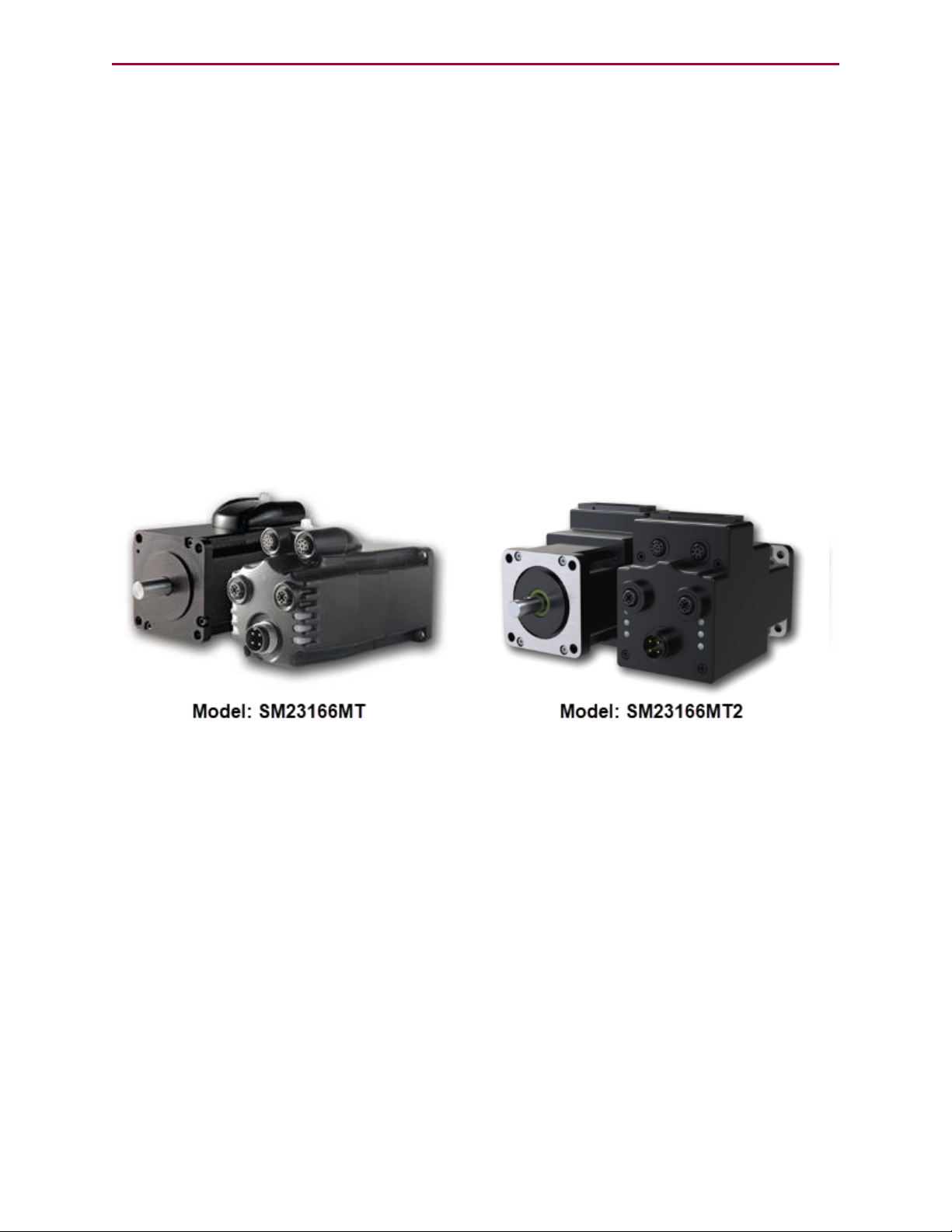
This guide describes the Moog Animatics Ethernet Serial Encapsulation protocol provided by
the Class 6 EtherNet/IP (EIP) SmartMotor™ (see the following figure). It describes the major
concepts that must be understood to integrate a SmartMotor slave with an Ethernet Serial
Encapsulation master device. It also includes a byte-by-byte discussion of the Moog Animatics
Ethernet Serial Encapsulation protocol.
NOTE: The feature set described in this version of the manual refers to SmartMotor
(–EIP option) firmware version 6.0.2.28 and netX firmware (NXF) version 3.3.0.3.
NOTE: The keepalive feature to reset broken connections requires firmware
6.0.2.41 or higher with netX firmware (NXF) version 3.4.0.5 or higher. Earlier
firmware versions will not activate this feature.
The Ethernet Serial Encapsulation protocol was developed by Moog Animatics as a means for
the Class 6 EtherNet/IP (EIP) motor to receive and send serial communications over Ethernet.
In addition to this protocol, Moog Animatics offers a variety of other fieldbus protocol options
for the Class 6 M-style motors, such as EtherNet/IP, Modbus, and more. Please contact Moog
Animatics for details.
Moog Animatics Class 6 SmartMotor™Ethernet Serial Encapsulation Guide,Rev. B
Page 5 of 32
Safety Information
Safety Information
This section describes the safety symbols and other safety information.
Safety Symbols
The manual may use one or more of the following safety symbols:
WARNING: This symbol indicates a potentially non-lethal mechanical hazard,
where failure to follow the instructions could result in serious injury to the
operator or major damage to the equipment.
CAUTION: This symbol indicates a potential minor hazard, where failure to
follow the instructions could result in slight injury to the operator or minor
damage to the equipment.
NOTE: Notes are used to emphasize non-safety concepts or related information.
Other Safety Considerations
The Moog Animatics SmartMotors are supplied as components that are intended for use in an
automated machine or system. As such, it is beyond the scope of this manual to attempt to
cover all the safety standards and considerations that are part of the overall machine/system
design and manufacturing safety. Therefore, the following information is intended to be used
only as a general guideline for the machine/system designer.
It is the responsibility of the machine/system designer to perform a thorough "Risk
Assessment" and to ensure that the machine/system and its safeguards comply with the
safety standards specified by the governing authority (for example, ISO, OSHA, UL, etc.) for
the locale where the machine is being installed and operated. For more details, see Machine
Safety on page 7.
Motor Sizing
It is the responsibility of the machine/system designer to select SmartMotors that are
properly sized for the specific application. Undersized motors may: perform poorly, cause
excessive downtime or cause unsafe operating conditions by not being able to handle the
loads placed on them. The Moog Animatics Product Catalog, contains information and
equations that can be used for selecting the appropriate motor for the application.
Replacement motors must have the same specifications and firmware version used in the
approved and validated system. Specification changes or firmware upgrades require the
approval of the system designer and may require another Risk Assessment.
Environmental Considerations
It is the responsibility of the machine/system designer to evaluate the intended operating
environment for dust, high-humidity or presence of water (for example, a food-processing
environment that requires water or steam wash down of equipment), corrosives or chemicals
that may come in contact with the machine, etc. Moog Animatics manufactures specialized
IP-rated motors for operating in extreme conditions. For details, see the Moog Animatics
Product Catalog.
Moog Animatics Class 6 SmartMotor™Ethernet Serial Encapsulation Guide,Rev. B
Page 6 of 32

Other Safety Considerations
Machine Safety
In order to protect personnel from any safety hazards in the machine or system, the
machine/system builder must perform a "Risk Assessment", which is often based on the ISO
13849 standard. The design/implementation of barriers, emergency stop (E-stop)
mechanisms and other safeguards will be driven by the Risk Assessment and the safety
standards specified by the governing authority (for example, ISO, OSHA, UL, etc.) for the
locale where the machine is being installed and operated. The methodology and details of
such an assessment are beyond the scope of this manual. However, there are various sources
of Risk Assessment information available in print and on the internet.
NOTE: The following list is an example of items that would be evaluated when
performing the Risk Assessment. Additional items may be required. The safeguards
must ensure the safety of all personnel who may come in contact with or be in the
vicinity of the machine.
In general, the machine/system safeguards must:
l
Provide a barrier to prevent unauthorized entry or access to the machine or system. The
barrier must be designed so that personnel cannot reach into any identified danger
zones.
l
Position the control panel so that it is outside the barrier area but located for an
unrestricted view of the moving mechanism. The control panel must include an E-stop
mechanism. Buttons that start the machine must be protected from accidental
activation.
l
Provide E-stop mechanisms located at the control panel and at other points around the
perimeter of the barrier that will stop all machine movement when tripped.
l
Provide appropriate sensors and interlocks on gates or other points of entry into the
protected zone that will stop all machine movement when tripped.
l
Ensure that if a portable control/programming device is supplied (for example, a handheld operator/programmer pendant), the device is equipped with an E-stop mechanism.
NOTE: A portable operation/programming device requires many additional
system design considerations and safeguards beyond those listed in this
section. For details, see the safety standards specified by the governing
authority (for example, ISO, OSHA, UL, etc.) for the locale where the
machine is being installed and operated.
l
Prevent contact with moving mechanisms (for example, arms, gears, belts, pulleys,
tooling, etc.).
l
Prevent contact with a part that is thrown from the machine tooling or other parthandling equipment.
l
Prevent contact with any electrical, hydraulic, pneumatic, thermal, chemical or other
hazards that may be present at the machine.
l
Prevent unauthorized access to wiring and power-supply cabinets, electrical boxes, etc.
l
Provide a proper control system, program logic and error checking to ensure the safety
of all personnel and equipment (for example, to prevent a run-away condition). The
control system must be designed so that it does not automatically restart the
machine/system after a power failure.
l
Prevent unauthorized access or changes to the control system or software.
Moog Animatics Class 6 SmartMotor™Ethernet Serial Encapsulation Guide,Rev. B
Page 7 of 32

Safety Information Resources
Documentation and Training
It is the responsibility of the machine/system designer to provide documentation on safety,
operation, maintenance and programming, along with training for all machine operators,
maintenance technicians, programmers, and other personnel who may have access to the
machine. This documentation must include proper lockout/tagout procedures for maintenance
and programming operations.
It is the responsibility of the operating company to ensure that:
l
All operators, maintenance technicians, programmers and other personnel are tested
and qualified before acquiring access to the machine or system.
l
The above personnel perform their assigned functions in a responsible and safe manner
to comply with the procedures in the supplied documentation and the company safety
practices.
l
The equipment is maintained as described in the documentation and training supplied by
the machine/system designer.
Additional Equipment and Considerations
The Risk Assessment and the operating company's standard safety policies will dictate the
need for additional equipment. In general, it is the responsibility of the operating company to
ensure that:
l
Unauthorized access to the machine is prevented at all times.
l
The personnel are supplied with the proper equipment for the environment and their job
functions, which may include: safety glasses, hearing protection, safety footwear,
smocks or aprons, gloves, hard hats and other protective gear.
l
The work area is equipped with proper safety equipment such as first aid equipment,
fire suppression equipment, emergency eye wash and full-body wash stations, etc.
l
There are no modifications made to the machine or system without proper engineering
evaluation for design, safety, reliability, etc., and a Risk Assessment.
Safety Information Resources
Additional SmartMotor safety information can be found on the Moog Animatics website; open
the file "109_Controls, Warnings and Cautions.pdf" located at:
http://www.animatics.com/support/moog-animatics-catalog.html
OSHA standards information can be found at:
https://www.osha.gov/law-regs.html
ANSI-RIA robotic safety information can be found at:
http://www.robotics.org/robotic-content.cfm/Robotics/Safety-Compliance/id/23
UL standards information can be found at:
http://ulstandards.ul.com/standards-catalog/
Moog Animatics Class 6 SmartMotor™Ethernet Serial Encapsulation Guide,Rev. B
Page 8 of 32

Additional Documents
ISOstandards information can be found at:
http://www.iso.org/iso/home/standards.htm
EUstandards information can be found at:
http://ec.europa.eu/growth/single-market/european-standards/harmonisedstandards/index_en.htm
Additional Documents
The Moog Animatics website contains additional documents that are related to the information
in this manual. Please refer to the following list.
Related Guides
l
Class 6 SmartMotor™ Installation and Startup Guide
http://www.animatics.com/cl-6-install-startup-guide
l
SmartMotor™ Developer's Guide
http://www.animatics.com/smartmotor-developers-guide
Other Documents
l
SmartMotor™ Product Certificate of Conformance
http://www.animatics.com/download/Declaration of Conformity.pdf
l
SmartMotor™ ULCertification
http://www.animatics.com/download/MA_UL_online_listing.pdf
l
SmartMotor Developer's Worksheet
(interactive tools to assist developer: Scale Factor Calculator, Status Words, CAN Port
Status, Serial Port Status, RMODE Decoder and Syntax Error Codes)
http://www.animatics.com/tools
l
Moog Animatics Product Catalog
http://www.animatics.com/support/moog-animatics-catalog.html
Moog Animatics Class 6 SmartMotor™Ethernet Serial Encapsulation Guide,Rev. B
Page 9 of 32

Additional Resources
Additional Resources
The Moog Animatics website contains additional resources such as product information,
documentation, product support and more. Please refer to the following list:
l
General company information:
http://www.animatics.com
l
Product information:
http://www.animatics.com/products.html
l
Product support (Downloads, How To videos, Forums, Knowledge Base, and FAQs):
http://www.animatics.com/support.html
l
Sales and distributor information:
http://www.animatics.com/sales-offices.html
l
Application ideas (including videos and sample programs):
http://www.animatics.com/applications.html
Moog Animatics Class 6 SmartMotor™Ethernet Serial Encapsulation Guide,Rev. B
Page 10 of 32

Motor Pinouts, Connections and Status LEDs
Motor Pinouts, Connections and
Status LEDs
The following sections describe the motor pinouts, system connections and the status LEDs.
Connecting the System 12
Class 6 M-Style EIP Motors: Connectors and Pinouts 12
Moog Animatics Industrial Ethernet Cables 13
Ethernet Custom Cable 13
Cable Diagram 14
Understanding the Status LEDs 15
Moog Animatics Class 6 SmartMotor™Ethernet Serial Encapsulation Guide,Rev. B
Page 11 of 32

Connecting the System
1
2 3
4
POWER INPUT
PIN
FUNCTION
DESCRIPTION
1
24 VDC
CONTROL I/O POWER
2
EARTH
CHASSIS GROUND
3
GND
MOTOR COMMON GROUND
4
48 VDC
MOTOR POWER
COMMUNICATION
PIN
FUNCTION
1
GND-COMMON
2
RS-485B CH0
3
RS-485A CH0
4
ENC A+ (IN/OUT)
5
ENC B- (IN/OUT)
6
ENC A- (IN/OUT)
7
5 VDC OUT
8
ENC B+
(IN/OUT)
1
2
3
4
5
6
7
8
1
2
3
4
5
6
7
8
9
10
11
12
I/Os
PIN
FUNCTION
DEFAULT
1
IN0
GENERAL PURPOSE
2
IN1
GENERAL PURPOSE
3
IN2/POSLIMIT
POSITIVE LIMIT
4
IN3/NEGLIMIT
NEGATIVE LIMIT
5
IN/OUT4
GENERAL PURPOSE
6
IN
/OUT
5
GENERAL PURPOSE
7
IN6
GENERAL PURPOSE
8
IN7-DRVEN
DRIVE ENABLE
9
OUT8/BRAKE
BRAKE OUTPUT
10
OUT9-NOFAULT
NOT FAULT
11
24 VDC OUT*
CONTROL I/O POWER
12
GND
MOTOR COMMON GROUND
INPUT OR OUTPUT
INPUT, DISCRETE OR ANALOG
POSSIBLE (SELECTABLE) FUNCTIONS
INPUT, DISCRETE OR ANALOG
INPUT
INPUT
INPUT/OUTPUT
INPUT/OUTPUT
INPUT
INPUT
OUTPUT
OUTPUT
POWER OUTPUT**
N/A
GENERAL PURPOSE
GENERAL PURPOSE
POSITIVE LIMIT OR GENERAL PURPOSE
NEGATIVE LIMIT OR GENERAL PURPOSE
GENERAL PURPOSE, OR EXTERNAL ENCODER
INDEX CAPTURE
GENERAL PURPOSE, OR INTERNAL ENCODER
INDEX CAPTURE
GENERAL PURPOSE, G COMMAND, OR
HOMING INPUT (ETHERCAT ONLY)
N/A
NOT FAULT
BRAKE OUTPUT OR GENERAL-PURPOSE OUTPUT
DRIVE ENABLE
*NOTE: 2 AMPS MAX **SUPPLIED FROM POWER INPUT PIN 1
CONTROL I/O POWER
RS-485 serial communication uses a
voltage differential signal. Appropriate
terminating resistors should be included
on the RS-485 network to ensure reliable
performance. For details, see the section
Power and RS-485 Com Multidrop.
1
2
3
4
Shield tied to motor
housing
LED 4: EtherNet/IP Link 1 Port LED
LED 2: EtherNet/IP Network Status LED
LED 0: Motor Drive LED
LED 5: Link EtherNet/IP Link 2 LED
LED 3: EtherNet/IP Module Status LED
LED 1: Motor Busy LED
USB Port LED
SD Card LED
EtherNet/IP
PIN
FUNCTION
1
+TX
2
+RX
3
-TX
4
-RX
*Input *Output
Connecting the System
The following sections show system connections and cable diagrams for typical Class 6 Mstyle EIPmotors.
Class 6 M-Style EIP Motors: Connectors and Pinouts
The following figure provides a brief overview of the connectors and pinouts available on the
Class 6 M-style SmartMotors. Additional connector specifications are available in the Class 6
SmartMotor™ Installation Guide.
The EtherNet/IP(industrial Ethernet) ports are used to connect the motor to the Ethernet
network. See the figure below for the location of those ports.
NOTE: When daisy-chaining SmartMotors for an Ethernet Serial Encapsulation
network, there is no specific IN or OUTEthernet port. In other words, either
Ethernet port can be used for the input or the output.
Moog Animatics Class 6 SmartMotor™Ethernet Serial Encapsulation Guide,Rev. B
Page 12 of 32

Moog Animatics Industrial Ethernet Cables
Moog Animatics Industrial Ethernet Cables
The following Industrial Ethernet cables are available from Moog Animatics.
M-style to M-style Ethernet Cable
This cable has M12 male threaded connectors at both ends. It is available in 1, 3, 5 and 10
meter lengths. For the standard cable, use part number CBLIP-ETH-MM-xM, where "x"
denotes the cable length. A right-angle version is also available; use part number
CBLIP-ETH-MM-xMRA.
M-style to RJ45 Ethernet Cable
This cable has an M12 male threaded connector at one end, and an RJ45 male connector at the
opposite end. It is available in 1, 3, 5 and 10 meter lengths. For the standard cable, use part
number CBLIP-ETH-MRJ-xM, where "x" denotes the cable length. A right-angle version is also
available; use part number CBLIP-ETH-MRJ-xMRA.
Ethernet Custom Cable
The following figure provides details for creating a custom shielded Ethernet cable.
NOTE: The motor end of the cable requires an industrial Ethernet connector.
Moog Animatics Class 6 SmartMotor™Ethernet Serial Encapsulation Guide,Rev. B
Page 13 of 32

Cable Diagram
Ethernet TCP/IP Network
Other Ethernet device:
- I/O block,
- Servo drive,
- etc.
TCP/IP Master
- PC,
- PLC,
- etc.
Moog Animatics
SmartMotor -EIP
Moog Animatics
SmartMotor -EIP
NOTE: Either Ethernet port can be used
to daisy-chain the motors.
Example Daisy-Chain Conguration
Ethernet TCP/IP Network
Other Ethernet device:
- I/O block,
- Servo drive,
- etc.
TCP/IP Master
- PC,
- PLC,
- etc.
Moog Animatics
SmartMotor -EIP
Moog Animatics
SmartMotor -EIP
NOTE: Either Ethernet port can be
used to connect the motors.
Example Star Conguration
Ethernet Hub or Switch
Cable Diagram
The following figures show a Ethernet Serial Encapsulation master connected to a series of
slave devices. Although only two configurations are shown, many different network topologies
are possible. Other devices (routers, gateways, etc.) may also be on the network. See the
previous page for cable part numbers.
NOTE: Unlike other fieldbus protocols, this configuration does not require
terminators at each end of the network.
NOTE: Unlike other fieldbus protocols, this configuration does not require
terminators at each end of the network.
Moog Animatics Class 6 SmartMotor™Ethernet Serial Encapsulation Guide,Rev. B
Page 14 of 32

Understanding the Status LEDs
Off No power
Solid green Drive on
Blinking green Drive off, no faults
Triple red flash Watchdog fault
Solid red Faulted or no drive enable input
Off Not busy
Solid green Drive on, trajectory in progress
Off No/bad cable; no/bad Link port
Solid green Link established
Flashing # red Flashes fault code* (see below)
when Drive LED is solid red
Blinking green Activity
Off No/bad cable; no/bad Link port
Solid green Link established
Blinking green Activity
Off No power
Flashing red/grn Power-up self test
Flashing green Standby
Solid green Device operational
Flashing red Minor fault
Solid red Major fault
Off No power or no IP address
Flashing red/grn Power-up self test
Flashing green No connections
Solid green Connected
Flashing red Connection timeout
Solid red Duplicate IP
LED 4: EtherNet/IP Link 1 Input LED
LED 2: EtherNet/IP Network Status LED
LED 0: Motor Drive LED
LED 5: EtherNet/IP Link 2 Output LED
LED 3: EtherNet/IP Module Status LED
LED 1: Motor Busy LED
LED 0: Motor Drive LED LED 1: Motor Busy LED
LED 3: EtherNet/IP Module Status LED
LED 5: EtherNet/IP Link 2 Output LED
LED 2: EtherNet/IP Network Status LED
LED 4: EtherNet/IP Link 1 Input LED
LED Status on Power-up:
• With no program and the travel limit inputs are low:
LED 0 solid red; motor is in fault state due to travel limit fault
LED 1 off
• With no program and the travel limits are high:
LED 0 solid red for 500 milliseconds then flashing green
LED 1 off
• With a program that only disables travel limits:
LED 0 red for 500 milliseconds then flashing green
LED 1 off
Flash
1
2
3
4
5
6
7
8
9
10
11
Description
NOT Used
Bus Voltage
Over Current
Excessive Temperature
Excessive Position
Velocity Limit
dE/Dt - First derivative of position error is excessive
Hardware Positive Limit Reached
Hardware Negative Limit Reached
Software Positive Travel Limit Reached
Software Negative Travel Limit Reached
LED1 Fault Codes:
*Busy LED pauses for 2 seconds before flashing the code
Flickering = On/Off in 0.1 sec; Blinking = On/Off in 0.5 sec; Flashing = separated by 1 sec for EtherNet/IP LEDs and 2 sec for Fault Codes
Flashing green Active
Flashing red Suspended
Solid red USB power detected, no
configuration
USB Active LED
Under cover:
USB Active LED
SD Card LED (for SD
Card-equipped motors)*
Blinking green Busy, do not remove card
Solid green
Card detected
Solid red
Card with no SmartMotor data
SD Card LED (for SD Card-equipped motors)
No card, bad or damaged cardOff
*For details, see “Understanding the SD Card” in the
Class 6 SmartMotor™ Installation & Startup Guide.
Understanding the Status LEDs
The following figure and tables describe the functionality of the Ethernet Serial Encapsulation
Status LEDs on the Class 6 EIP SmartMotor.
Moog Animatics Class 6 SmartMotor™Ethernet Serial Encapsulation Guide,Rev. B
Page 15 of 32

Using Ethernet Serial Encapsulation
Using Ethernet Serial Encapsulation
The following sections describe how to enable Ethernet Serial Encapsulation communications
with your SmartMotor, along with information on supported function codes, input registers
and holding registers.
Ethernet Serial Encapsulation Description 17
TCPPort 17
UDP Port 17
Detecting the Motors in SMI 18
Setting the IPAddress 18
Supported/Not-Supported Functionality 19
Supported Functionality 19
Not-Supported Functionality 20
Ethernet Serial Encapsulation Communications Setup 21
Ethernet Serial Encapsulation Sample Command Sequences 21
UDP (User Datagram Protocol) Discovery Example 23
TCP (Transmission Control Protocol) Command Examples 24
Moog Animatics Class 6 SmartMotor™Ethernet Serial Encapsulation Guide,Rev. B
Page 16 of 32

Ethernet Serial Encapsulation Description
Ethernet Serial Encapsulation Description
Ethernet Serial Encapsulation is a protocol developed by Moog Animatics that allows host
software, such as SMI, to communicate via serial commands over Ethernet. The Moog
Animatics Class 6 EtherNet/IP (EIP) SmartMotor supports communication with a PLC, HMI, or
other host device over Ethernet.
Unlike Modbus RTU serial communication, the OCHNcommand is not needed or used for
Ethernet Serial Encapsulation communication. In fact, once the motors are connected to the
Ethernet network, they will be able to communicate with the Ethernet Serial Encapsulation
master if DHCPis used, or they will simply need a static IPaddress if DHCPis not being used.
TCPPort
There is a single instance of the TCP port that acts like a serial command parser. Note that a
second concurrent attempt to connect will be rejected. However, if the first connection is
closed by the client, then the motor will accept another connection.
CAUTION: There is no security check or other method available to disable the
TCP port. Therefore, the network is assumed to be "friendly" (i.e., secure,
ready and safe to connect to).
TCP Port 10001
The TCPport uses ASCII commands to create a "pipeline" to the same handling as a serial
port, as follows:
l
Prepend with a byte of the value: 0x80
l
Terminate with a byte of the value: 0x20 (a space)
l
Responses terminate with 0x0d
Example:
l
Command: 0x80RPA0x20 = "0x80RPA " (note there is a space at the end).
l
Response: 102330x0d = the number 10233 with the byte value 0x0d at the end.
UDP Port
Optionally, and unrelated to the TCP connection, a broadcast to port 30718 over UDP can be
used to discover the SmartMotor(s).
UDP port 30718
Send a UDP packet broadcast:
To address 255.255.255.255, port 30718 with the BCAST flag:
Moog Animatics Class 6 SmartMotor™Ethernet Serial Encapsulation Guide,Rev. B
Page 17 of 32

Detecting the Motors in SMI
1.
Send the packet from your port 30718
2.
Send this data:
l
Datagram length: four bytes
l
Content (from first to last): 0x00, 0x00, 0x00, 0xf6
Listen for response back to your port 30718:
1.
Check that data length received is 30 bytes.
2.
Check that the first four bytes (0-3) are:
0x00, 0x00, 0x00, 0xf7
3. For the remaining bytes:
l
Bytes 4-23 should all be 0
l
Bytes 24-29 represent the MAC ID of the motor
Detecting the Motors in SMI
When using the Detect Motors feature in SMI to detect the SmartMotor(s), they will be
detected as "Ethernet". Note the following:
l
The ability to change the SmartMotor IP address through the SMI menus and dialogs will
not function. However, you can use SMI software's Terminal window to issue commands
that set the IP address. See the SMI software's online help for details on the Terminal
window.
l
The SmartMotor "webpage" feature, also used to set the IPaddress, will not function.
Therefore, the IP address must be set through either:
l
The IP Control command (IPCTL), or
l
The SmartMotor's USBport
For details, refer to the following section.
Setting the IPAddress
As mentioned previously, for Ethernet Serial Encapsulation on the SmartMotor, the IPaddress
can be either static or dynamic (DHCP). The default operation is dynamic addressing. For
applications requiring a fixed IPaddress, it must be set using the IP control command (IPCTL)
through either:
l
The Ethernet port, or
l
The SmartMotor's USBport
The IPCTLcommand allows you to change the IPaddress of the SmartMotor. The default
setting is "0.0.0.0" for IP address, subnet mask, and gateway disabled/automatic. Three
function codes (0, 1, and 2) are available for setting a specific IPaddress, a specific subnet
mask, and/or a specific gateway address, respectively. It uses the form:
IPCTL(function,"string")
Moog Animatics Class 6 SmartMotor™Ethernet Serial Encapsulation Guide,Rev. B
Page 18 of 32

Supported/Not-Supported Functionality
l
function is one of the following codes:
function Description
0 Set IP address
1 Set subnet mask
2 Set gateway
l
"string" is formatted as an IP address and entered as a string
For example:
IPCTL(0,"192.168.0.10") 'Set the IP address to 192.168.0.10
For more details on the IPCTLcommand, see the SmartMotor™ Developer's Guide. For details
on the Ethernet and USB ports, see the Class 6 SmartMotor™ Installation &Startup Guide.
Supported/Not-Supported Functionality
Supported Functionality
A small set of functions are supported for access to these basic SmartMotor operations:
l
Report commands: RPA, RSP, etc.
Report commands are shown in the SmartMotor Developer's Guide. They can be
identified by looking at the command lists (near the end of the guide) for commands
that begin with a superscript "R" character, for example:RPA,RSP,RPC etc.
Commands that begin with an "R"character that is not superscript are not report
commands, for example: RANDOM=, RESUME, RETURN, RETURNI, RUN, RUN?.
NOTE: Also, refer to the Not-Supported Functionality section.
For more details, refer to Example with a String Response on page 24 and Example with
a Numeric Response on page 25.
l
Assign a variable: a=400
For more details, refer to Example of Assigning a Variable on page 26.
Moog Animatics Class 6 SmartMotor™Ethernet Serial Encapsulation Guide,Rev. B
Page 19 of 32

Not-Supported Functionality
l
Motion commands
All the motion commands listed in the Motion Control section of the SmartMotor
Developer's Guide will work with the exception of the following (as these are not yet
supported in Class 6 SmartMotors):
l ADTS
l ATS
l DTS
l VTS
l PTS
l PRTS
l GS
l PRTSS
l PTSS
l RPTSD
l RPTST
l
User program download, run and upload.
For more details, refer to Example of Program Downloading, Running and Uploading on
page 27.
l
Channel 2 is always open (see Not-Supported Functionality)
l
TCP keepalive feature (requires firmware 6.0.2.41 or higher with netX firmware (NXF)
version 3.4.0.5 or higher.)
Not-Supported Functionality
The following SmartMotor functions are not supported:
l
Serial "data" mode is not supported (for example, RGETCHR)
Report commands specific to the serial port, like RGETCHR, RGETCHR1, etc. (reporting
the state of the actual serial ports) will report a value without problem. However,
commands like RGETCHR2, RLEN2 are not supported specific to the state of the serial
encapsulation channel itself; i.e., you can’t put the serial encapsulation into "data"
mode.
Any command that can be performed on the serial port should also work through
Ethernet Serial Encapsulation. There are a few operations, however, that don't apply to
this environment:
l
Setting or reading the baud rate specific to that port
l
OCHN, serial interpolation time sync
l
Serial addressing
l
Open channel and change channel (OCHN and CCHN, respectively) commands are not
supported
NOTE: Channel 2 is always open.
Moog Animatics Class 6 SmartMotor™Ethernet Serial Encapsulation Guide,Rev. B
Page 20 of 32

Ethernet Serial Encapsulation Communications Setup
Ethernet Serial Encapsulation
Communications Setup
This topic contains Ethernet Serial Encapsulation communications setup information.
For a typical Ethernet Serial Encapsulation application:
l
Ethernet Serial Encapsulation requires the Class 6 "–EIP" SmartMotor model. Verify that
you have the correct motor.
l
Verify the type of motor addressing being used. Note the following:
l
For dynamic IP (DHCP)addressing (SmartMotor default), there is no need to set
an IPaddress on the motor.
l
For static IPaddressing, you will need to set a static IP address on the motor. For
more details, see Setting the IPAddress on page 18.
l
There is no need to open the Ethernet Serial Encapsulation port, it is already open by
default (using TCP port 10001). Therefore, no special program is needed.
l
There is no need for a node ID—the IP address serves as the motor's identification.
Note that the Node ID is typically assumed to be "0" in Ethernet Serial Encapsulation.
Command Purpose Value
ETHCTL(100, value) Enable/disable
ports
ETHCTL(110, value) Keepalive time for
Ethernet serial
encapsulated
connection.
-1 default
0 disable TCP communications port
and UDP discovery port.
1 enable TCPcommunications port
only
2 enable UDP discovery port only
3 enable TCP communications port
and UDP discovery port.
(default)
-1 default (3 seconds)
0 disable
1-127 keepalive time (seconds)
Ethernet Serial Encapsulation Sample Command Sequences
Non-Volatile
Setting
Yes
Yes
This topic contains some sample Ethernet Serial Encapsulation command sequences. These
examples show the data sent from and received by SMI software communicating with a
Moog Animatics Class 6 SmartMotor™Ethernet Serial Encapsulation Guide,Rev. B
Page 21 of 32

Ethernet Serial Encapsulation Sample Command Sequences
SmartMotor. For these examples, an open-source software (Wireshark network protocol
analyzer) is used to show the communications between SMI software and the SmartMotor.
NOTE: There are various utilities available for this purpose. Therefore, Moog
Animatics does not endorse any particular one—the selection depends on the
requirements of your application.
For each of the following sections:
l
Section title = action being performed
l
Output = formatted byte stream sent from master to the SmartMotor
l
Input = formatted byte stream received by the master from the SmartMotor
For the following tables:
NOTE: A table is provided to illustrate the parts of the byte sequence only. The
byte sequence must be transmitted as a stream of bytes shown in the Output/Input
strings above the table (i.e., no pause or null for the blank cells).
These items unique to the UDPDiscovery Example:
l
Operation Code (Bytes 0-3) = specifies the operation being performed
l
Reserved (Bytes 4-23) = reserved bytes
l
MAC address (Bytes 24-29) = the MAC address of the responding motor
These items are common to TCPCommand Examples:
l
Prefix = required stream prefix (Output always 80; Input = N/A)
l
Command = Output byte string representing the desired command
l
Response = Input byte string representing the response from the motor
l
Terminator = required stream terminator (Output always 20; Input = 0d)
Moog Animatics Class 6 SmartMotor™Ethernet Serial Encapsulation Guide,Rev. B
Page 22 of 32

UDP (User Datagram Protocol) Discovery Example
UDP (User Datagram Protocol) Discovery Example
Output: 00 00 00 f6
Input: 00 00 00 f7 00 00 00 00 00 00 00 00 00 00 00 00 00 00 00 00 00 00 00 00 00 02 a2 2b 41 ff
UDP Packet Data Payload
Operation Code
(Bytes 0-3)
Output 00 00 00 f6
Input 00 00 00 f7 00 00 00 00 00 00 00 00 00 00 00
A table is provided to illustrate the parts of the byte sequence only. The byte sequence must be transmitted as a
stream of bytes shown in the Output/Input strings above the table (i.e., no pause or null for the blank cells).
Output:
Reserved (Bytes 4-23) MAC addr ess (Bytes 24-29)
00 02 a2 2b 41 ff
00 00 00 00 00 00 00 00 00
Input:
Moog Animatics Class 6 SmartMotor™Ethernet Serial Encapsulation Guide,Rev. B
Page 23 of 32

TCP (Transmission Control Protocol) Command Examples
TCP (Transmission Control Protocol) Command Examples
Example with a String Response
This is a TCP example with a string response; the RSP command replies with "06250/6.0.2.30"
Output: 80 52 53 50 20
Input: 30 36 32 35 30 2f 36 2e 30 2e 32 2e 33 30 0d
TCP Stream
Prefix Command Response Terminator
Output 80 52 53 50
("RSP")
Input 30 36 32 35 30 2f 36 2e 30 2e 32 2e 33 30
("06250/6.0.2.30")
A table is provided to illustrate the parts of the byte sequence only. The byte sequence must be transmitted as a
stream of bytes shown in the Output/Input strings above the table (i.e., no pause or null for the blank cells).
Output:
20
0d
Input:
Moog Animatics Class 6 SmartMotor™Ethernet Serial Encapsulation Guide,Rev. B
Page 24 of 32

TCP (Transmission Control Protocol) Command Examples
Example with a Numeric Response
This is a TCP example with a numeric response as a string; the RPA command reports the
value 1105.
Output: 80 52 50 41 20
Input: 31 31 30 35 0d
TCP Stream*
Prefix Command Response Terminator
Output 80 52 50 41
("RPA")
Input 31 31 30 35
("1105")
A table is provided to illustrate the parts of the byte sequence only. The byte sequence must be transmitted as a
stream of bytes shown in the Output/Input strings above the table (i.e., no pause or null for the blank cells).
Output:
20
0d
Input:
Moog Animatics Class 6 SmartMotor™Ethernet Serial Encapsulation Guide,Rev. B
Page 25 of 32

TCP (Transmission Control Protocol) Command Examples
Example of Assigning a Variable
This is a TCPexample of assigning a numeric value to a variable: a=400.
Output: 80 61 3D 34 30 30 20
Input: 31 31 30 35 0d
TCP Stream*
Prefix Command Response Terminator
Output 80 61 3D 34 30 30
("a=400")
Input N/A - See Input figure below
A table is provided to illustrate the parts of the byte sequence only. The byte sequence must be transmitted as a
stream of bytes shown in the Output/Input strings above the table (i.e., no pause or null for the blank cells).
Output:
20
Input:
The following figure shows the SmartMotor ACKnowledgement back to the PC/master.
However, it doesn't contain any data to respond to; it is just to keep the TCP connection alive.
Moog Animatics Class 6 SmartMotor™Ethernet Serial Encapsulation Guide,Rev. B
Page 26 of 32

TCP (Transmission Control Protocol) Command Examples
Example of Program Downloading, Running and Uploading
This is a TCPexample of downloading, running and uploading the following program:
' My test program
WHILE 1
PRINT2("Hi there Ethernet host",#13)
WAIT=1000
LOOP
END
Downloading the Program
Output: 80 4C 4F 41 44 20 LOAD command s ent to motor
Input: 06 ACK from motor
Output:
Input: 06 ACK from motor
Output:
Input: 06 ACK from motor
Output:
Input: 06 ACK from motor
Output:
Input: 06 ACK from motor
Output: 02 87 00 00 00 59 08
Output: FF FF 20 Output, but no reply expected
Output: 80 52 43 4B 53 20 RCKScommand
Input: 30 30 30 30 30 30 20 30 30 31 31 36 44 20 50 0D Two checksum values and P (pass)
24 36 30 30 30 30 30 31 31 36 44 30 30 30 30 34
30 30 30 30 30 30 30 30 30 30 30 24 57 30 30 33
43 4C 45 20 31 0A 50 52 49 4E 54 32 28 22 48 69
20 74 68 65 72 65 20 45 74 68 65 72 6E 65 74 20
68 6F 73 74 22 2C 23 31 33 29 0A 57 41 49 54 3D
31 30 30 30 0A 24 4C 30 30 30 30 50 0A 45 4E 44
0A FF 24 74 65 73 74 20 65 74 68 65 72 6E 65 74
2E 73 6D 78 00 20 20 20 20 20 20 10 0B 16 13 07
32 character block of program download
32 character block of program download
32 character block of program download
32 character block of program download
Remaining character block of program download
SMISerial Data Analyzer (shows Output and Input)
Moog Animatics Class 6 SmartMotor™Ethernet Serial Encapsulation Guide,Rev. B
Page 27 of 32

TCP (Transmission Control Protocol) Command Examples
Running the Program
Output: 80 52 55 4E 20 RUNc ommand
48 69 20 74 68 65 72 65 20 45 74 68 65 72 6E 65
74 20 68 6F 73 74 0D
Input:
Output: 80 45 4E 44 20 END command
. . .
48 69 20 74 68 65 72 65 20 45 74 68 65 72 6E 65
74 20 68 6F 73 74 0D
"Hi there..." messages from program loop
SMISerial Data Analyzer (shows Output and Input)
Uploading the Program
Output: 80 55 50 4C 4F 41 44 20 UPLOAD command sent to motor
Input: 57 48 49 4C 45 20 31 0A 16 character block of upload from motor
Output: 06 ACK from host
Input: 50 52 49 4E 54 32 28 22 16 character block of upload from motor
Output: 06 ACK from host
Input: 48 69 20 74 68 65 72 65 16 character block of upload from motor
Output: 06 ACK from host
Input: 20 45 74 68 65 72 6E 65 16 character block of upload from motor
Output: 06 ACK from host
Input: 74 20 68 6F 73 74 22 2C 16 character block of upload from motor
Output: 06 ACK from host
Input: 23 31 33 29 0A 57 41 49 16 character block of upload from motor
Output: 06 ACK from host
Input: 54 3D 31 30 30 30 0A 4C 16 character block of upload from motor
Output: 06 ACK from host
Input: 4F 4F 50 0A 45 4E 44 0A 16 character block of upload from motor
SMISerial Data Analyzer (shows Output and Input)
Moog Animatics Class 6 SmartMotor™Ethernet Serial Encapsulation Guide,Rev. B
Page 28 of 32

Troubleshooting
Troubleshooting
The following table provides troubleshooting information for solving common problems. For
additional support resources, see the Moog Animatics Support page at:
http://www.animatics.com/support.html
Issue Cause Solution
Communication and Control Issues
Motor control
power light does
not illuminate.
Motor does not
communicate
with SMI.
Motor not detected or not communicating
through TCP (Ethernet port in
SMI).
Motor
disc onnects from
SMI sporadically.
Red PWR SERVO
light illuminated.
Common Faults
Bus voltage fault. Bus voltage is either too
Overcurrent
occurred.
Excessive
temperature
fault.
Control power is off,
disc onnected or
incorrectly wired.
Motor has routed drive
power through driveenable pins.
Motor is equipped with
the DE option.
Transmit, receive or
ground pins are not
connected correctly.
Motor program is stuck in
a continuous loop or is
disabling
communications.
IP address and/or netmask not set.
Feature disabled See ETHCTL(100,<value>) command.
COM port buffer settings
are too high.
Poor connection on serial
cable.
Power supply unit (PSU)
brownout.
Critical fault. To discover the source of the fault, use the Motor View tool located
high or too low for
operation.
Motor intermittently drew
more than its rated level
of curr ent. Does not cease
motion.
Motor has exceeded
temperature limit of 85°C.
Motor will remain
unresponsive until it cools
down below 80°C.
Check that control power is connected to the proper pins and
turned on. For connection details, see Connecting the System on
page 12.
Ensure cabling is correct and drive power is not being delivered
through the 15-pin connector.
To energize control power, apply 24-48 VDC to pin 15 and ground
to pin 14.
Ensure that transmit, receive and ground are all connected
properly to the host PC.
To prevent the program from running on power up, use the
Communications Lockup Wizard located on theSMI software
Communications menu.
See IPCTL command, or check DHCP s erver.
Adjust the COM port buffer settings to their lowest values.
Check the serial c able connections and/or replace it.
PSU may be too high-precision and/or undersized for the
application, which causes it to brown-out during motion. Make
moves less aggressive, increase PSU size or change to a linear
unregulated power supply.
on the SMI software Tools menu.
Check servo bus voltage. If motor uses the DE power option,
ensure that both drive and control power are connected.
Consider making motion less abrupt with softer tuning
parameters or acceleration profiles.
Motor may be undersized or ambient temperature is too high.
Consider adding heat sinks or forced air cooling to the system.
Moog Animatics Class 6 SmartMotor™Ethernet Serial Encapsulation Guide,Rev. B
Page 29 of 32

Troubleshooting
Issue Cause Solution
Excessive
position error.
Historical
positive/negative
hardware limit
faults.
Programming and SMI Issues
Several
commands not
recognized
during compiling.
The motor's commanded
position and actual
position differ by more
than the user-supplied
error limit.
A limit switch was tripped
in the past.
Motor does not have limit
switches attached.
Compiler default firmware
version set incorrectly.
Increase error limit, decrease load or make movement less
aggress ive.
Clear errors with the ZS command.
Configure the motor to be used without limit switches by setting
their inputs as general use.
Use the Compiler default firmware version option in the SMI
software Compile menu to select a default firmware version
closest to the motor's firmware version. In the SMI software, view
the motor's firmware version by right-clicking the motor and
selecting Properties.
Moog Animatics Class 6 SmartMotor™Ethernet Serial Encapsulation Guide,Rev. B
Page 30 of 32


PN: SC80100017-001, Rev. B
Ethernet Serial Encapsulation
 Loading...