

Page 1
MOOG
Manual IMI220-145D001
Parison Controller
Page 2
PARISON CONTROLLER
Document Revision
Hardware
Software Rev.
Author
Date
Preliminary
Preliminary
Preliminary
Lstrabla - nfrassine
6th Dec 2004
1.02
1.02
1.02
rfacchi - nfrassine
31st Aug 2005
MAN145-UM-A02A-EN
IMI220-145A002
2.01
rfacchi - nfrassine
5th Oct 2005
MAN145-UM-A03A-EN
IMI220-145A003
3.01
sverga - nfrassine
29th May 2006
MAN145-UM-A03B-EN
IMI220-145A003
3.01 - 3.02
sverga - nfrassine
June 2006
MAN145-UM-B01A-EN
IMI220-145B001
3.04 - 3.05
4.01 - 4.02 - 4.03 - 4.04
– 4.05
sverga - nfrassine
June 2010
MAN145-UM-C01A-EN
IMI220-145C001
5.01
nfrassine
July 2012
MAN145-UM-D01A-EN
IMI220-145D001
6.07
sverga – mamoruso
July 2017
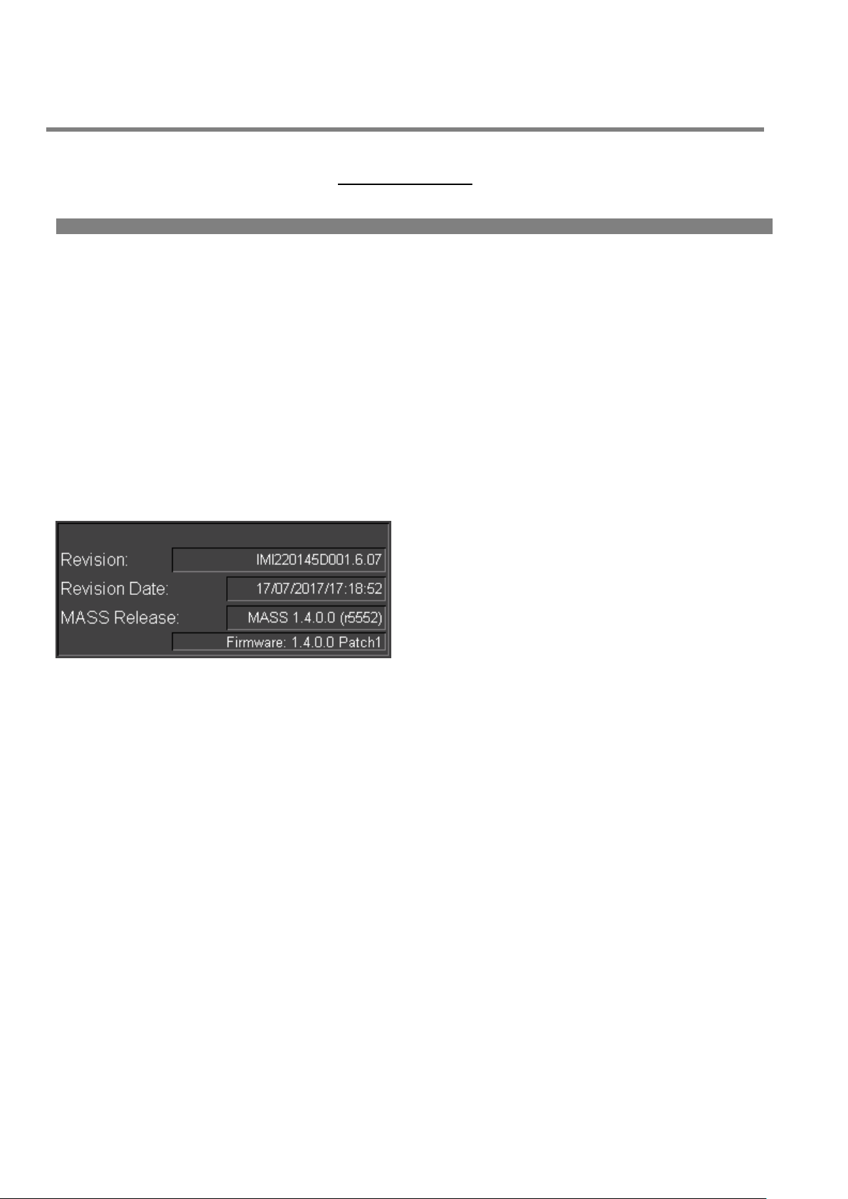
Revision: Number of the current revision application
inside in the PLC.
Revision Date: Date of the current revision application
inside in the PLC.
MASS Release: MASS version related to the actual
application.
Firmware: Firmware release; can differ from MASS
release
Revision History
moog
2 MAN145-UM-D01A-EN Moog Italiana srl - Bergamo
Page 3

PARISON CONTROLLER
moog
1 Installation.
1.1 Installation Overview.
Since there are many makes, models and vintages of blow moulding machines it is impossible to give specific
instructions as to the mounting, wiring and plumbing schemes to use. Different machines have different
requirements that the installer must ascertain before beginning the actual physical installation of the system. A
careful examination of the machine and some thoughtful planning beforehand will usually produce a good,
serviceable installation. There are some suggestions that hopefully will make your installation smooth and provide
many years of trouble free operation.
It is recommended that, if space is available on the machine, the programmer and its various electrical components
be mounted in a separate enclosure. While it might be possible to mount these components in the machine’s main
electrical cabinet, quite a bit of electrical “noise” and heat is usually generated there. While the Parison Controller
was designed with some degree of tolerance for these conditions it must be remembered that it is, in essence, a
computer.
To minimize any detrimental effects on the system that can be sometimes caused in such an environment, it may
be easier and wiser to circumvent any problems before they are created. The old adage “An ounce of prevention…”
can definitely apply here.
If using a separate enclosure or not, thoughtful layout of components is quite important. Remember, for future
troubleshooting it is important to consider accessibility to terminals to allow for voltage readings and the ability to
reach fasteners so components can be removed and replaced. Cable routing should also be considered to prevent
stretching of cables, straining of connections, pinch points and sharp edges that could damage a wire or cable.
Transducer and valve cables should be run through a “Seal-Tite” type of flexible, liquid tight conduit. Although it is
much faster and easier to run them over the machine unprotected, enclosing them in conduit provides protection
against physical damage as well as protection against insulation breakdown due to airborne chemical.
Cabling should also be run away from sources of heat (extruders, accumulators, and heater bands) and strong
electrical fields (motors, transformers, etc.).
The programmer can be mounted anywhere convenient to the operator station but should be located away from
areas where it could be damaged by falling objects or flooded by broken coolant or hydraulic lines.
Cable lengths to valves and transducers should be kept as short as possible to minimize line loss and signal
corruption, but long enough to provide movement of machine members for unrestricted operation and machine
maintenance. When routing cables it is wiser to avoid possible noise sources or areas of potential damage than to
minimize cable lengths.
Moog Italiana srl - Bergamo MAN145-UM-D01A-EN 3
Page 4

PARISON CONTROLLER
moog
1.2 Hydraulic Installation.
Hydraulic installation involves the mounting and plumbing of filters, servo-valve manifolds, cylinders, etc.
If the programmer is being installed as a replacement for another programmer all the necessary components should
already be in place. If not, the following suggestions are offered:
Do not reuse old hose, pipe fittings or tubing. Contamination in old plumbing is almost impossible to
effectively remove and can cause problems in future servo-valve reliability. Old fittings that have been
painted and assembled with old thread sealing compounds will not only introduce contamination, but are
1.3 Hydraulic Filtration.
Clean oil is the key to reliable hydraulic system operation. Dirt, silt and sludge in the system increase operating
temperatures by decreasing heat exchanger efficiency and create excessive wear on pumps, directional and relief
valves and valve seats. Contamination breeds contamination by wearing hoses and other hydraulic components
from the inside.
Moog servo-valves are designed to operate with an ISO code of 14/11. While this may be lower than what you are
accustomed to, the benefits of improved filtration will show up not only in increased servo-valve life but will help to
reduce premature machine wear and the frequency of oil related failures.
Moog offer a full line of filters and filter systems with element ratings starting at 3 microns, flow-rates from 10 to
100 gallons per minute, and operating pressures as high as 3,000 psi. There are a number of good filter systems
available and, even if a Moog filter is not chosen, it is strongly urged you employ one of these other filter systems
on your machine.
High-pressure filter assemblies should be plumbed between the high-pressure hydraulic supply and the “P”
(pressure) port of the servo-valve manifold(s). Plumbing from the filter outlet to the “P” port should be completed
with steel tubing or pipe.
If the machine employs a hydraulic accumulator to maintain stability in the machine’s hydraulic system, the filter
should be installed after the accumulator and before the valve manifold(s).
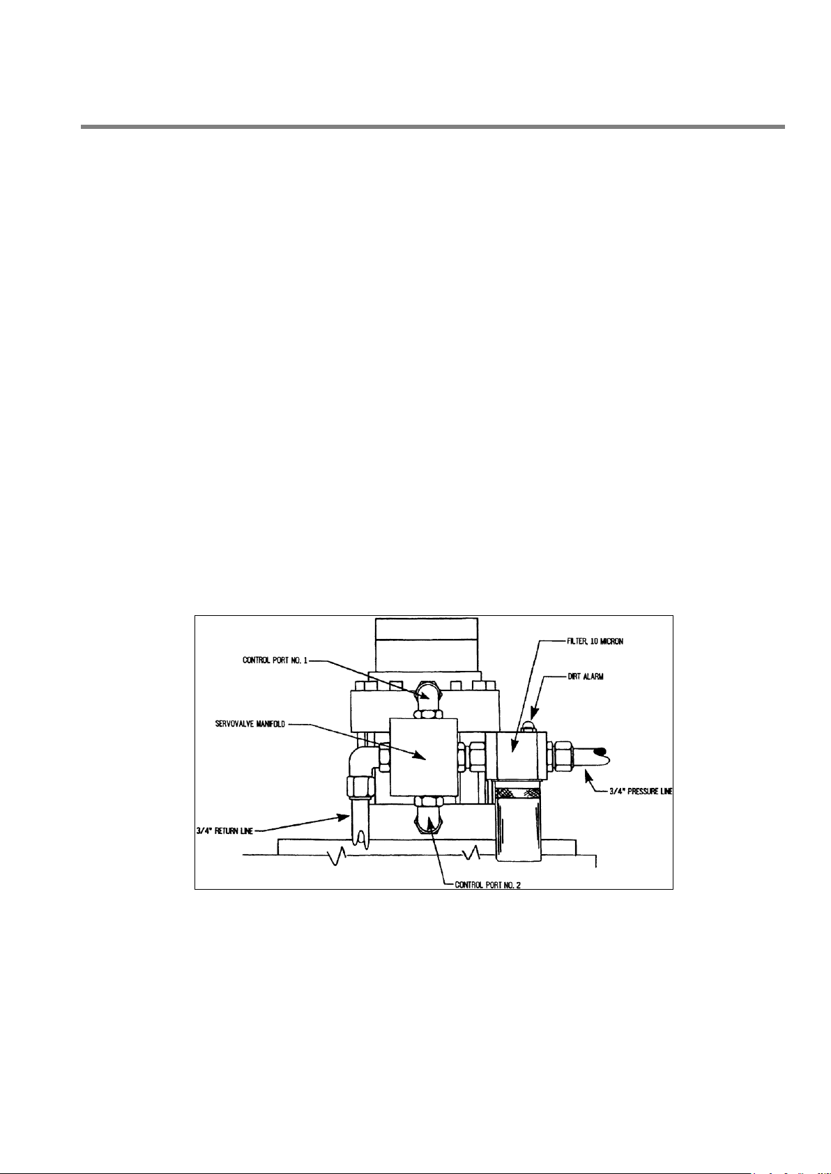
1.4 Servovalve Manifolds.
Servo-valve mounting is accomplished with the use of manifolds for each head. These manifolds allow for easy
removal of the valves to facilitate system flushing or valve replacement in the event of failure.
harder to work with and can contribute to added installation time.
Before assembling any new plumbing, inspect it carefully to insure that there are no metal filings or foreign
matter left over from cutting or assembly. Now is the best time to clean it out, before it can get into the
hydraulic system.
Replace the hydraulic oil or have it analyzed by a reputable lab. Depending on your maintenance program,
the oil may not have been checked for some time. Now is a good time to perform any oil-related
maintenance BEFORE the servo-valves are installed.
If you are replacing the oil remember to filter it as you pump it into the machine. New oil right from the
refinery is sometimes the dirtiest oil in the shop.
4 MAN145-UM-D01A-EN Moog Italiana srl - Bergamo
Page 5
PARISON CONTROLLER
moog
Moog servo-valves used in blow moulding Parison control are most often internally piloted devices. This means
that the manifolds used will have 4 ports that connect to the machine’s hydraulic system:
“P” port is the incoming high-pressure supply to the valve.
“T” or “R” port is the servo-valve return to tank.
“A” or “C1” port is one of the controlled ports. This should plumb to one end of the programming cylinder.
“B” or “C2” port is the other controlled port. This should plumb to the other end of the programming cylinder.
Some manifolds may be supplied with an additional fifth port labeled “X”. These manifolds are designed for use
with hydraulic systems capable of supplying an independent source of pilot pressure. If the need for this port is
uncertain, contact Moog Field Engineering for additional information.
There is no specification as to which controlled port should plumb to which end of the programming cylinder. The
following suggestions are offered concerning plumbing:
Try to keep the overall length of the controlled port lines as close to equal as possible.
Keep the servo-valve manifold as close to the programming cylinders as possible. The shorter the length
It is EXTREMELY IMPORTANT that plumbing between the controlled ports of the manifolds and the programming
cylinders be completed with solid tube or pipe. Do Not Use Hoses To Make These Connections! Hydraulic supply
up to the filter and the return lines from the servo-valve manifolds can be done with hose if desired.
In a great number of cases, the solid hydraulic lines that connect the controlled ports to the programming cylinders
will provide enough support for the servo-valve and manifold combination. If the machine is prone to excessive
vibration it would be wise to fabricate some type of bracket to support the servo-valve assembly.
A typical servo-valve and manifold installation is depicted below:
of the control lines, the more accurate position control will be.
Try to plumb all the valves the same way. (All “A” ports to the top of the cylinders or all “B” ports to the top
of the cylinders.) This will reduce confusion and make wiring easier later.
Figure 1
Moog Italiana srl - Bergamo MAN145-UM-D01A-EN 5
Page 6
PARISON CONTROLLER
moog
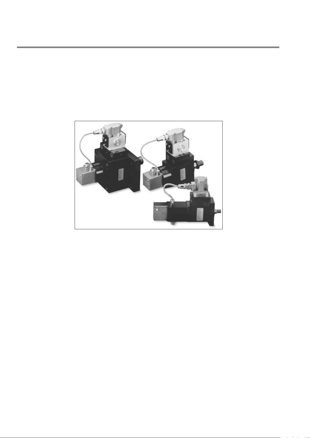
1.5 Servoactuators.
A servo-actuator is a device, which can be used to take the place of the standard hydraulic cylinder. It combines
the cylinder, DCDT position transducer and servo-valve manifold into one compact, pre-adjusted package. Servoactuators can help reduce hydraulic installation time significantly and make calibration faster and easier.
There are a number of servo-actuators available with different specifications and mounting hardware, therefore no
specific information will be supplied in this document. Please contact Moog if more information is required on a
specific model or type.
Figure 2
1.6 Flushing.
Once all the hydraulic work has been completed you can start the process of flushing the hydraulic system. This
step is recommended to remove as much of the foreign matter left behind in the hydraulic system as possible
before installing the servo-valves.
It is also recommended that the system be flushed every time the reservoir is drained and refilled, a cylinder is
replaced, or a pump or any other major hydraulic component on the machine is replaced.
The first step in flushing is to remove the servo-valves from their manifolds or actuators and replace with the proper
flushing blocks. Install the flushing element in the high-pressure filter assembly and make sure the dirt alarm has
been properly reset. (Flushing elements are identified by a red band printed around the filter element.)
Jog the pumps to insure that there are no major leaks in the hydraulic system. If all looks tight start the pumps and
allow them to run. After a short run time carefully inspect all the hydraulic fittings and lines to insure there are no
leaks.
Periodically check the filter dirt alarm on the high-pressure filter to see if it has tripped. If it has, stop the pumps and
replace the flushing element with a new one. Reset the dirt alarm and restart the pumps. Allow them to run while
periodically inspecting the dirt alarm.
The system has been satisfactorily flushed when the pumps can run for two complete hours without tripping the
dirt alarm.
6 MAN145-UM-D01A-EN Moog Italiana srl - Bergamo
Page 7

PARISON CONTROLLER
CAUTION
The flushing element is a LOW-PRESSURE element designed to be used in conjunction with the flushing
blocks. Failure to replace it with the correct high-pressure filter element after removing the flushing blocks
will result in the filter element collapsing and possibly damaging the machine.
NOTE
On some machines when the flushing blocks are installed in place of the servo-valves, hydraulically
operated devices may not function. The flushing blocks are configured to direct pressure back to tank
allowing the system to be flushed at low pressure. Because of this, no pressure will be created in the
hydraulic system.
moog
After flushing is complete, stop the pumps and replace the flushing element with a standard high-pressure filter
element. Replace the flushing blocks with the servo-valves. Remember to reconnect the electrical connectors.
1.7 A Word About Hydraulic Pumps.
One of the most common failures seen in parison control valves is a buildup varnish in the valve. This is usually
caused by oil overheating and breaking down. Most standard petroleum based hydraulic fluids begin to reach their
temperature specification somewhere between 130 and 150 degrees Fahrenheit (between 55 and 65 degrees
Celsius). While you may never surpass this temperature while running, it can easily be exceeded when the pumps
are off and the machine heats are on. The stationary oil in the valve absorbs the heat and can quickly surpass the
oil’s breakdown point.
To reduce the possibility of this happening it is suggested that anytime the heats are on, the pumps should continue
to run. The oil moving through the valve will actually act as a coolant and help to prolong servo-valve life.
1.8 Transducers Installation.
The Parison Controller uses DCDT position transducers to feed back programming cylinder position information to
the controller. A separate DCDT is required for each individual head.
If servo-actuators of the type described above are being used, the DCDT is integrated into the actuator package
and has been pre-adjusted at the factory. No further adjustment is required.
If the programmer is used in a position based application there is also a linear position transducer that is needed
to monitor the position of the reciprocating screw or accumulator push-out cylinder.
Moog Italiana srl - Bergamo MAN145-UM-D01A-EN 7
Page 8

PARISON CONTROLLER
moog
1.9 DCDT Position Transducers.
In order to maintain accuracy and repeatability of the programming cylinder motion, care must be taken when
mounting the DCDT tooling position transducer(s).
A DCDT can be mounted with the transducer body as the stationary element and the core as the moving member
or the core can be stationary and the body can move. Whatever method is used, the stationary element must be
rigidly mounted on a non-moving portion of the machine frame to provide a reference for piston movement.
Please note the following precautions when mounting the transducer:
The core must move freely in the body. There should be no side loading of the core nor should the core
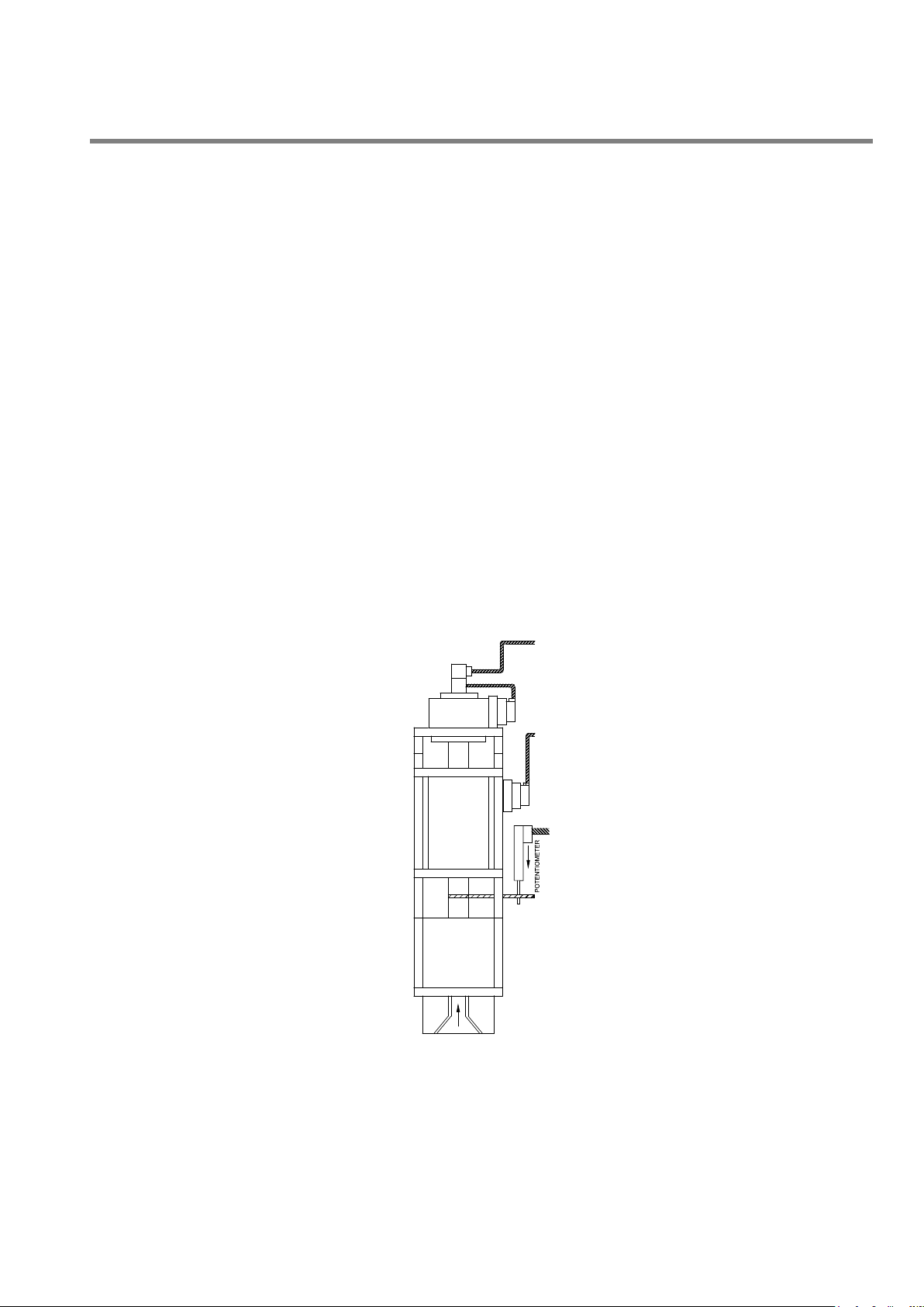
A typical DCDT transducer installation using the moving core method is depicted in the drawing below.
rod be bent in order to make it align with the transducer body.
Mountings for both core and transducer body must be rigid. There should be no free play in any of the
brackets and the brackets should be made of a stiff material, which will not bend or give, with normal
machine vibration.
Provision must be made to allow for adjustment of the stationary element of the transducer. The
transducer’s position will need to be adjusted during calibration to bring the programming cylinder’s stroke
into the usable portion of the DCDT’s stroke. The ability to align the body with the core will also make future
DCDT replacement easier, if necessary.
When designing the DCDT mounting brackets allow for some type of anti-rotational device to keep the core
and body properly aligned.
Figure 3
Note the provisions made for the vertical adjustment of the DCDT body and the anti-rotational arrangement
incorporated to keep the core and body aligned.
8 MAN145-UM-D01A-EN Moog Italiana srl - Bergamo
Page 9
PARISON CONTROLLER
moog
1.10 Linear Position Transducer (position based applications ONLY).
Since the profile is synchronized to the position of the push out ram, the Parison Controller requires a means to
track the ram throughout the push-out stroke. In addition, to keep the profile points properly positioned on the
Parison, the Parison Controller must have control over the accumulator or reciprocating screw’s FULL (End of Fill.)
and EMPTY (End of Extr.) points. Both of these tasks are accomplished by the signal provided from the linear
position transducer, also referred to as a linear pot.
The transducer can be mounted so that the shaft EXTENDS FROM the pot body during push-out, or RETRACTS
INTO the body during push-out, whichever makes for a more convenient mounting method.
As with DCDT’s, there are several precautions that should be observed when mounting linear position transducers:
The pot body and shaft must be as parallel to the push out ram as possible. This will prevent side loading
of the transducer shaft and premature failure of the bushings in the transducer body.
The transducer should never be at the full mechanical end of its stroke in either direction. When mounting
be sure that the shaft is at least 0.25” (~5 mm) from its mechanical end stop when the push out cylinder is
at full bottom (empty).
The body should be rigidly mounted to eliminate the possibility of movement caused by machine vibration.
There should be no more than 1/16 inch (~1.5 mm) of end play in the transducer shaft in the direction of
ram movement when the shaft is secured to the ram follower assembly.
The end of the shaft should never be screwed down tightly to the follower assembly. Instead, the ball joint
on the shaft should be allowed to “float” slightly up and down the securing screw. This will reduce any
stresses caused by the slight misalignment between transducer and cylinder that are always present.
Figure 4
Moog Italiana srl - Bergamo MAN145-UM-D01A-EN 9
Page 10
PARISON CONTROLLER
Figure 5
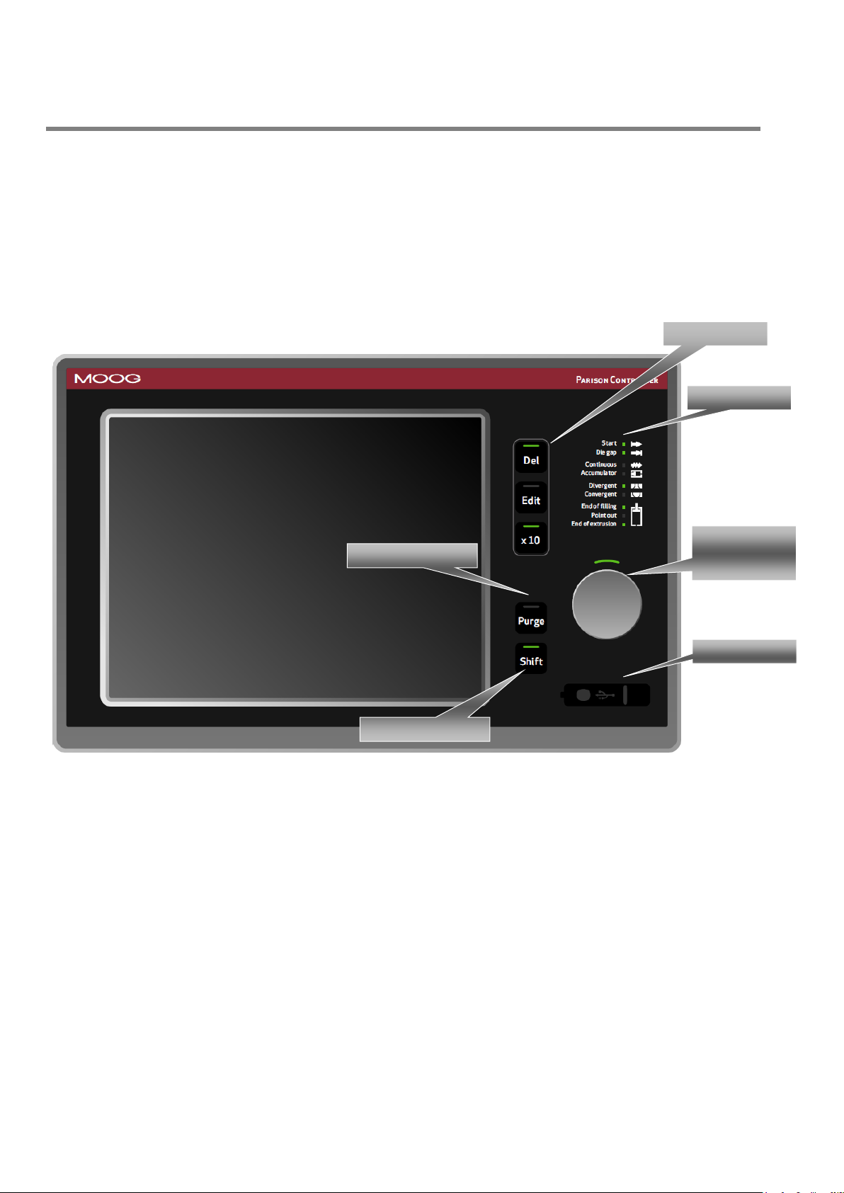
Leds panel
Rotary Knob
SET key
Usb Device
Buttons
Purge Command
Shift key
moog
2 System Architecture.
2.1 Terminal (Front).
The Panel Operator is the place where all the interactions happen between the operator and the Parison
Controller.
The Operative Panel is constituted by a LCD TFT 10.4 inches touch screen and by groups of buttons.
The Parison Controller looks as follows:
10 MAN145-UM-D01A-EN Moog Italiana srl - Bergamo
Page 11
PARISON CONTROLLER
Figure 6
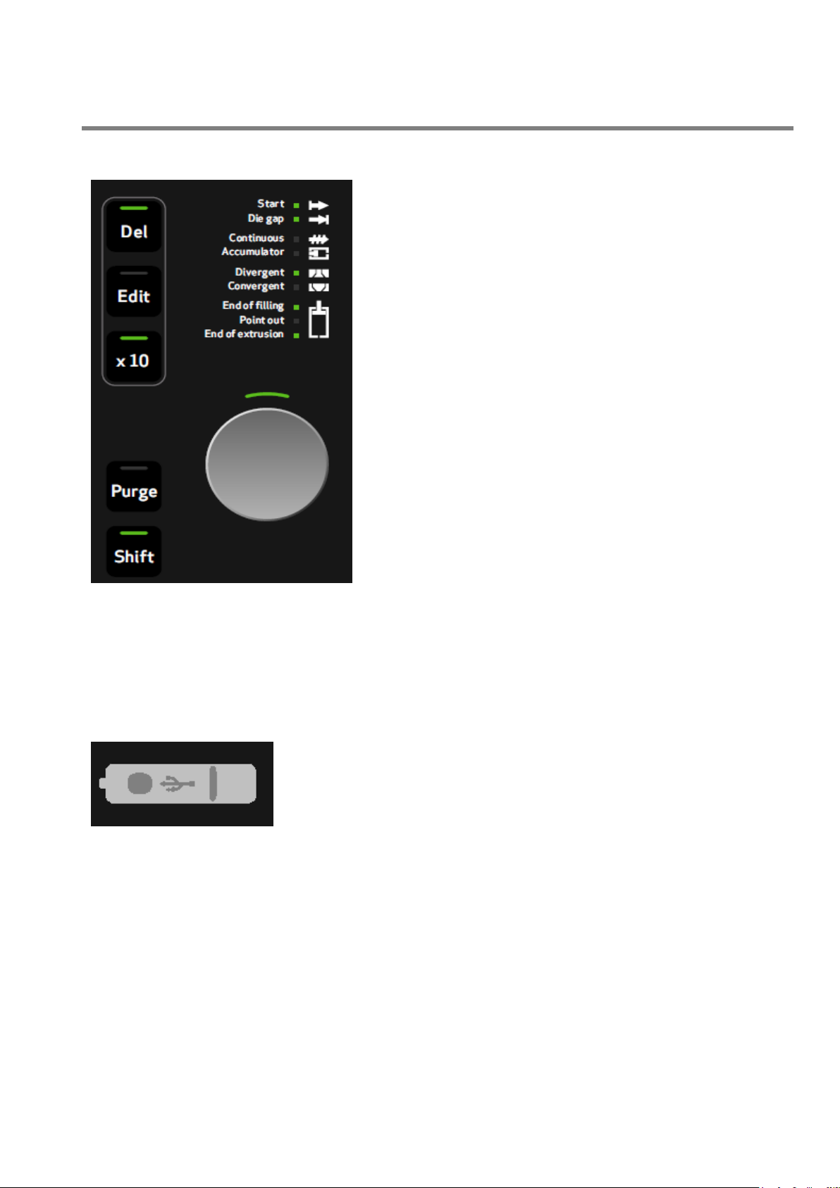
Entry Knob: Used to change the value of various functions.
Rotation in a clockwise sense to increment and anticlockwise
sense to decrement. It is also used as a SET key to confirm a
change.
Del: Delete key. When a field is focused and this button is
pressed the content of the field is erased.
Edit: This button allows to enter the Parison field and edit the
profile. The button LED is ON. Push the Edit button again to end
the Parison editing. The button LED turns OFF.
X10: Increase the sensitivity of the entry knob by a factor of 10.
When X
10
is active the associated led is ON.
Figure 7
Usb device: Allows to save or load the recipes on an external memory.
2.1.1 Fast Access Keys and Knob.
moog
Purge: This button starts the movement of the heads to the purge position; as long as the key “PURGE” is active.
Shift: This button used contemporarily with another button changes the operation of it. This is explained for each
button in the relative pages.
2.1.2 Usb device.
Moog Italiana srl - Bergamo MAN145-UM-D01A-EN 11
Page 12

PARISON CONTROLLER
Figure 8
Start: Lit when the cycle Start (1 or 2) signal is received.
Die gap: Lit when the Die Gap signal is received (only in position accumulator
mode).
Continuous: Lit when the “Continuous Extrusion” machine type is selected.
Accumulator: Lit when “Accumulator” machine type is selected.
Divergent: Lit when “Divergent” die is selected. Normally it is reported to the
head number 1. If the work page visualizes another head this led reports to this
same head.
Convergent: Lit when “Convergent” die is selected. Normally it is reported to
the head number 1. If the work page visualizes another head this led reports to
this same head.
moog
2.1.3 Display Led panel.
End of filling: Lit at the end of the accumulator filling (only in position accumulator mode).
Point out: Lit when each serial marker point is reached.
End of extrusion: Lit at the end of extrusion. (both in continuous extrusion and accumulator mode)
12 MAN145-UM-D01A-EN Moog Italiana srl - Bergamo
Page 13

PARISON CONTROLLER
Green numbers
The fields that can be reached by cursor and can be changed.
Grey numbers
The fields that can’t be reached by cursor and can’t be changed.
Blue bargraphs
Show the value of an analog output.
Yellow numbers
Show actual value.
Yellow bargraphs
Show actual value (feedback e.t.a.).
White
The texts on the screens.
Text left bottom: Shows
the actual recipe that is
working.
Lock: No password inserted.
Acc. Resp: Access Responsible Level on. For changing this password enter in Technical
Level and enter in setup machine.
Acc. Tech: Access Technical Level on. This password is fixed by Moog.
Bottom page: soft
key to change the
page
Alarm line: If there are one or more
alarms on the alarms page, the alarms
are displayed at the bottom of each
page.
Min and Max: Minimum and maximum are displayed in the status line.
In the example on the left the minimum valid value is 0, while the
maximum is 5000.
moog
2.2 General page description.
2.2.1 Colours assignment for all pages:
2.2.2 Page Header:
Center: Shows the page title.
Date and time of day: Show the actual day, date and hour of the system. For adjustment go to the Technical level
or a Resp. level password.
Text right bottom: (yellow) Shows the current level state:
The other one shows the current number page.
2.2.3 Page Bottom:
This line shows the last alarm and changes the back colour depending on the priority. On the left of the text the
number shows the code of the alarm displayed at the moment.
Moog Italiana srl - Bergamo MAN145-UM-D01A-EN 13
Page 14
PARISON CONTROLLER
Figure 9
Figure 10
Figure 11
Figure 12
moog
2.3 Change of Setpoints.
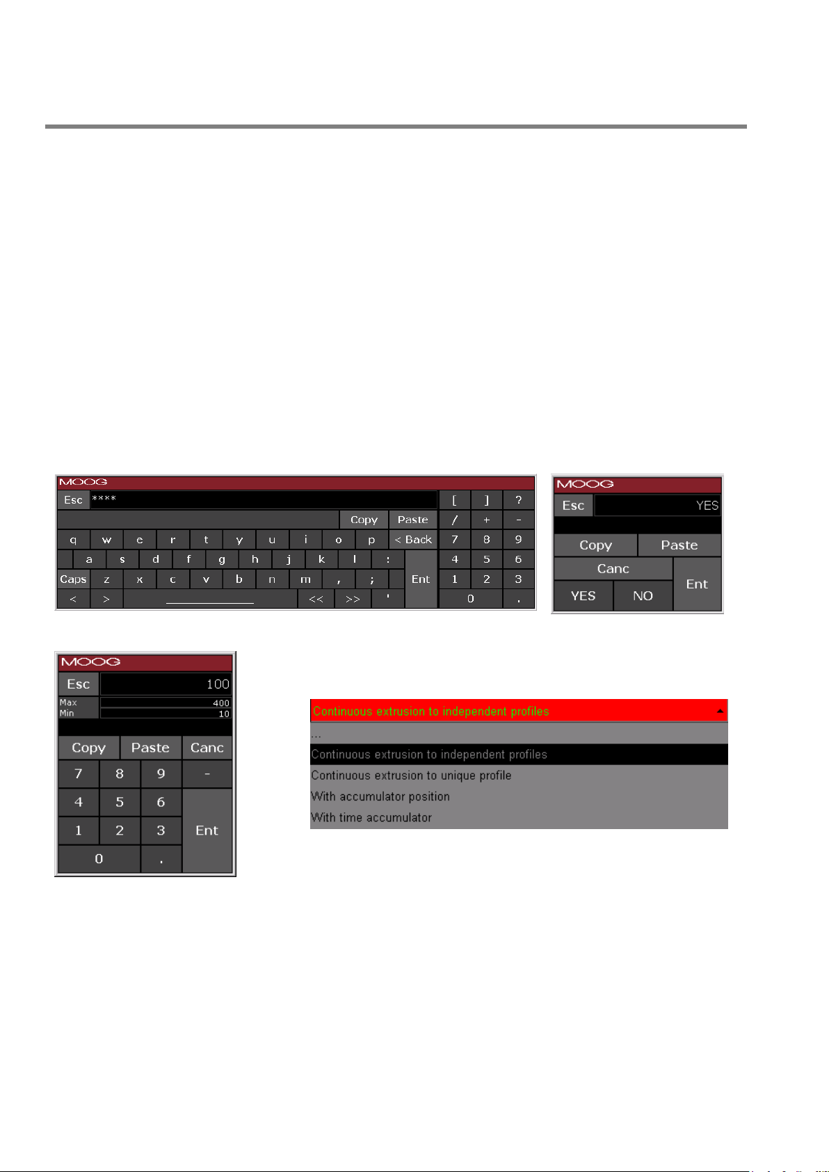
If the cursor is on a numeric, Boolean, multi text list, alphanumeric field (green), the value can be changed.
Numeric fields: insert the desired number with the rotation of the Entry Knob. In clockwise the numbers increase.
It is possible to insert the decimal value only rotating the Knob and it is possible to insert the value left of the dot
with X10 multiplication factor and entry knob. Confirm by Set key.
Boolean fields: switch to YES/NO with rotate Entry Knob. In clockwise it is YES selection. Confirm by Set key.
Multi text list fields: rotate Entry Knob (one or more times) to scroll forward or (one or more times) to scroll
backward until desired text is displayed. Press Set key to accept the change.
Alphanumeric fields: Insert the first character alphanumeric with the rotation of the Entry Knob, move to the right
using the shift key + entry knob, using again the entry knob insert the following character. When the string is
completed confirm by Set key.
If a field need not to be changed (i.e. after typing a wrong number or changing the intention) move the cursor
away.
When a field is in variation with the insertion of a new data the led near Set Key is lit and the field changes colour.
It is also possible to modify all the existing fields using the relative keyboard (double click on the field):
14 MAN145-UM-D01A-EN Moog Italiana srl - Bergamo
Page 15
PARISON CONTROLLER
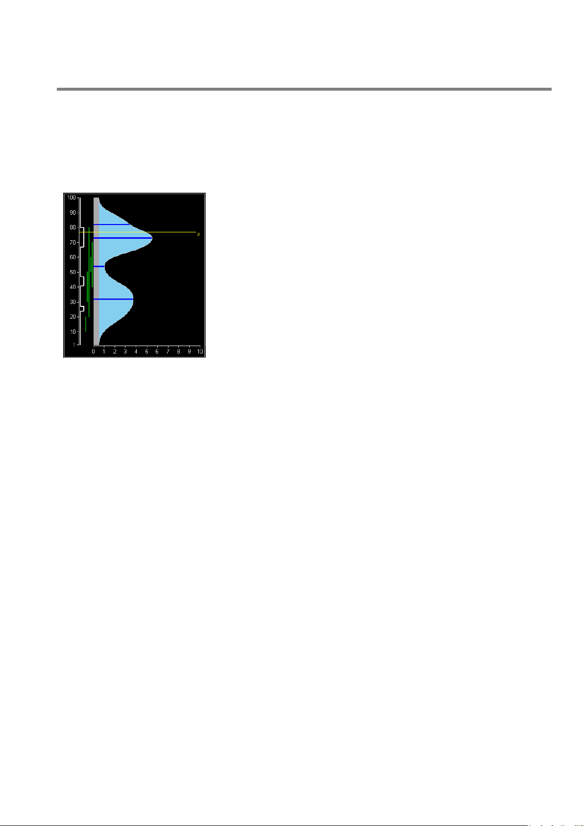
Figure 13
Working point panel: vertical histogram showing current working point
(for selected head).
Serial markers panel: (visible if select ON in Setup Machine Page)
vertical panel containing a logic status diagram of serial marker status
along the profile. The left position is OFF, the right position is ON.
Synchronism panel: (visible if set 1 or plus at number synchronism on
Setup Machine Page) vertical panel containing from 0 to max 5 vertical
lines as programmed synchronization points; each synchronism signals is
defined through start and stop points (which define synchronism line
width) and through type.(with accumulator machine).
Profile panel: area where the profile appears (maximum 400 points).
Each point can get a value from 0 through 10000 (100.00%); the profile is
drawn making an interpolation among some basic points (masters),
highlighted by horizontal line. Interpolation can be of various types: Bezier
curves, linear, flat, parabolic 1 (parabola with tangent 0 on end point) or
parabolic 2 (parabola with tangent 0 on start point); an interpolation can
be selected in a different way for each area available between a master
and the next one. The parison field, besides showing current profile, can
display the offset between programmed profile and the feedback profile
actually present on the head. On a profile it is possible to place some
markers allowing to physically detect a parison point.
2.4 The Parison field.
2.4.1 Field appearance.
When parison field is displayed by browser, it's sub-divided into 4 parts:
Starting from left you can see:
moog
2.4.2 Editing profile.
The cursor can be moved on a parison field using UP, DOWN arrow keys. The cursor position is drawn by a dashed
line; when the field is focused, the cursor is drawn by a continuous line. In this phase any operation involving a
change in current profile invokes field editing (background colour becomes orange); the field shows both original
profile and that being edited (changing page is possible going back to original profile).
When focus is on parison field, these operations are allowed:
2.4.3 Normal functioning:
- Arrows
- by pressing UP/DOWN arrow keys it's possible to move the cursor by a point upwards or downwards.
- by pressing +/- keys it's possible to change the amplitude of the current cursor point; the value changes
according to the amount contained in Increase; the changed point is setup as a master.
- Entry knob
- by the rotation it's possible to change the amplitude of the current cursor point; the value changes according
to the amount contained in Increment; the changed point is setup as a master.
- by pressing SHIFT + Rotation it's possible to move the cursor upwards or downwards.
Moog Italiana srl - Bergamo MAN145-UM-D01A-EN 15
Page 16
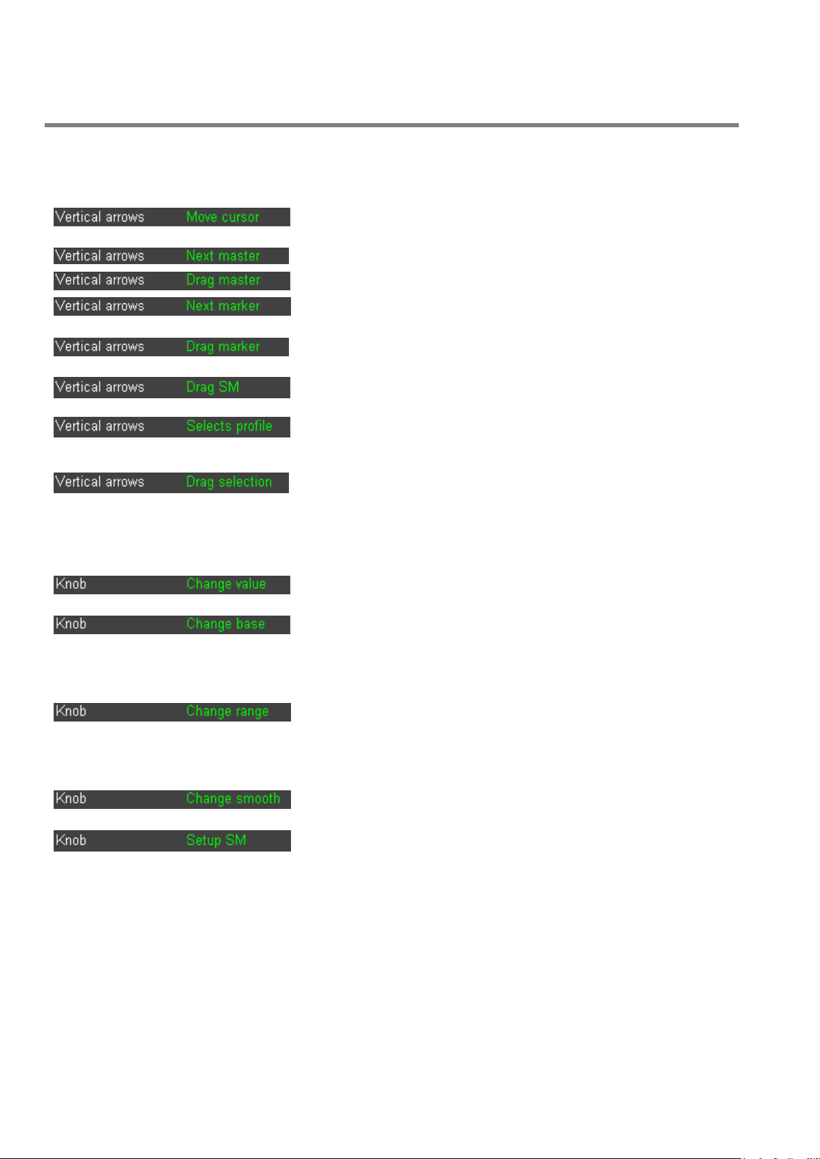
PARISON CONTROLLER
Move cursor: move the cursor up and down (default
functioning)
Next master: move the cursor among the masters
Drag master: drag the master up and down
Next marker: move the cursor among the markers
(visible if select ON in Setup Machine Page)
Drag marker: drag the marker up and down. (visible if
select ON in Setup Machine Page)
Drag SM: drag the Serial Marker up and down. (visible
if select ON in Setup Machine Page)
Selects profile: select a part of the profile. It is possible
to select an area of points (reverse mode): selection is
active from previous master to next master
Drag selection: drag the selection up and down. If an
area is selected, it is possible to move it: if the motion
meets a master, it will be cancelled
Rotate the knob to change the Value (default
functioning)
Rotate the knob to change the Base. To increase the
minimum value (base) of the whole profile: all points are
translated in such a way that the profile keeps the same
look. The base can be changed up to that the maximum
value of the profile is 100
Rotate the knob to change the Range. To increase/
decrease the whole profile range: all points are
proportionally changed in such a way that the profile
keeps the same look. The range can be changed up to
that the maximum value of the profile is 100
Rotate the knob to change the Smooth. The value can
be from 0.5 up to 2 and it is only for Bezier interpolation
Rotate the knob to setup the Serial Marker (if selected
ON in Setup Machine Page)
2.4.4 Other possibilities.
It is possible to select (F5) how the vertical arrows have to work.
moog
It is possible to select (F6) how the Knob has to work.
16 MAN145-UM-D01A-EN Moog Italiana srl - Bergamo
Page 17

PARISON CONTROLLER
moog
2.4.5 Other function keys possibilities.
by pressing the key DEL it's possible to remove a master on the profile, in correspondence to the cursor
point.
by pressing the function key programmed as Toggle marker (F2) it's possible to add or remove a marker
on the profile in correspondence with the cursor point. By the function key DEL it's possible to remove a
marker.
If a master and a marker are both on the same point, press the key DEL to remove the marker as first.
by pressing the function key programmed as Select interpolation (F4) it's possible to change the type of
the interpolation area between two masters, the choice selection is made among Bezier curves, linear, flat,
parabolic 1, parabolic 2.
by the function key programmed as Clear (F3) it's possible to completely delete the current profile. The
When the serial marker panel is visible (set the parameter to ON in Setup Machine Page), the following operations
are possible:
PLC profile will be updated only when the operation is confirmed by pressing the Set Key.
modify the serial marker using F5 to set Vertical arrows to Drag SM and F6 to select Knob as Setup SM.
The SM can be dragged using the arrows.
the status of the serial marker can be switched ON and OFF using the knob or
2.5 Functionality.
2.5.1 Safe Condition.
Necessary conditions to start issuing a new profile are:
Temperature Ok ON
Emergencies ON
Alarm OFF
machine in automatic ON
Purge OFF
Tooling OFF
The digital input “machine in automatic” has to be ON during the normal work and has to be OFF
during the machine configuration. (Machine type selection, number of heads selection, number of
point selection, number of extruder selection, output command type selection, heads and
accumulator calibration and die type selection)
2.5.2 Language packages.
PARISON CONTROLLER is supplied with a language package (application rev. IMI220145D001.X.XX). It is
possible to choose among the following languages:
English, Italian, German, French, Spanish, Portuguese, Danish, Russian, Turkish, Greek, Chinese and Japanese.
and - keys.
+
Moog Italiana srl - Bergamo MAN145-UM-D01A-EN 17
Page 18

PARISON CONTROLLER
moog
2.5.3 Elements.
PARISON CONTROLLER can be configured to manage up to 4 heads.
Each regulator uses an analog input to acquire the mandrel opening and an analog output to drive the mandrel
positioning actuator.
The regulator can operate in closed loop (with no-intelligent actuators) or in open loop (with intelligent actuators
that operate in closed loop stand alone).
The input value is calibrated in range 0% - 100.00% through definition of upper extreme voltage and lower extreme
voltage. In case of intelligent actuators the calibration points are set to 0 mV and 10000 mV if it is not necessary to
make the calibration.
PARISON CONTROLLER can be configured to manage 1 accumulator.
A regulator in position in accumulation mode requires that the accumulator management is setup on fourth channel.
The setpoint generated by thickness regulator depends on the accumulator position in injection stroke relating to
the total injection stroke.
Input value is calibrated in range 0% - 100.00% through definition of full accumulator voltage (100% and input
higher than empty position) and empty accumulator voltage (0% and input lower than full position). It is possible to
exchange the analog output polarity to ignore the actuator connection polarity. The default polarity value waits for
increasing voltage values to bring the accumulator to empty position.
The input calibration should be made in this way:
It is possible to indicate a voltage to be applied on extrusion control output and activate empty accumulator
calibration procedure. The system automatically detects mechanical end-of-stroke, stores this value and interrupts
extrusion control. Using manual methods, the accumulator should be brought to empty and full position and it is
possible to manually confirm the positions.
PARISON CONTROLLER can be configured to manage up to 2 extruders.
It is possible to decide whether to use the extruder or not and which channel it should be associated to. It can be
associated to:
A thickness regulator in continuous extrusion.
A thickness regulator in time accumulation.
Accumulator.
It is possible to decide whether the extruder is driven by an analog or digital command. In case of analog command
the output voltage of a channel is the speed setpoint. In case of a digital command two digital outputs allow increase
or decrease of speed.
Extruder with analog command:
o It is possible to calibrate the input with: 0 speed voltage, maximum voltage, and maximum speed.
The speed is expressed in RPM.
o It is possible to calibrate the output with: maximum speed, voltage to reach maximum speed.
o These setpoints can be setup: speed to be reached, rising ramp in RMP/sec., falling ramp in
RPM/sec., minimum speed, maximum speed.
Extruder with digital command:
Timer Switch
The Parison Controller can manage a weekly timer switch to activate the machine heating system and it can
manage a production counter.
o You can setup the maximum ON time for digital output depending on a manual command.
18 MAN145-UM-D01A-EN Moog Italiana srl - Bergamo
Page 19
PARISON CONTROLLER
Figure 16
chose the page number and press the softkey
Figure 17
it is also possible to perform the touch calibration keeping pressed the SET
key (entry knob) for 10 seconds
moog
2.5.4 Access.
PARISON CONTROLLER manages 3 access levels to protect data entry:
1. minimum access for machine user. Lock: no password inserted.
2. responsible access for responsible. Acc. Resp. For changing this password enter in Technical Level and
enter in setup machine.
3. service access for installer/serviceman. Acc. Tech. This password is fixed by Moog.
Access to levels 2 and 3 is password-protected. Level 2 persists at power down and power up, while level 3 does
not.
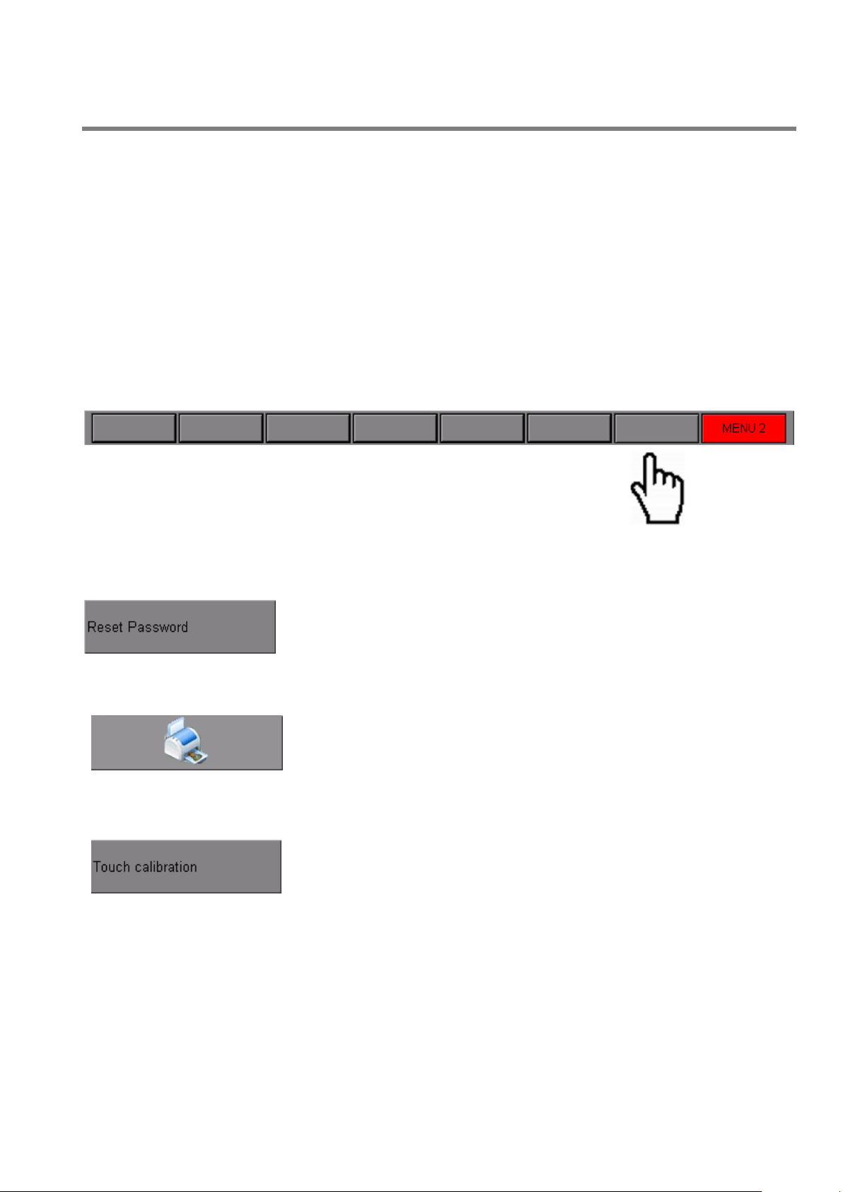
2.5.5 Keyboard test page.
From the input/output page and in manual mode (digital input 13 has to be OFF)
Keeping pressed the button F7 (next to the button MENU 2) for 5 seconds it is possible to access the test page
In this page it is possible to:
Reset the password:
Figure 15
Print the pages:
Perform the touch calibration:
-
Figure 14
Moog Italiana srl - Bergamo MAN145-UM-D01A-EN 19
Page 20
PARISON CONTROLLER
moog
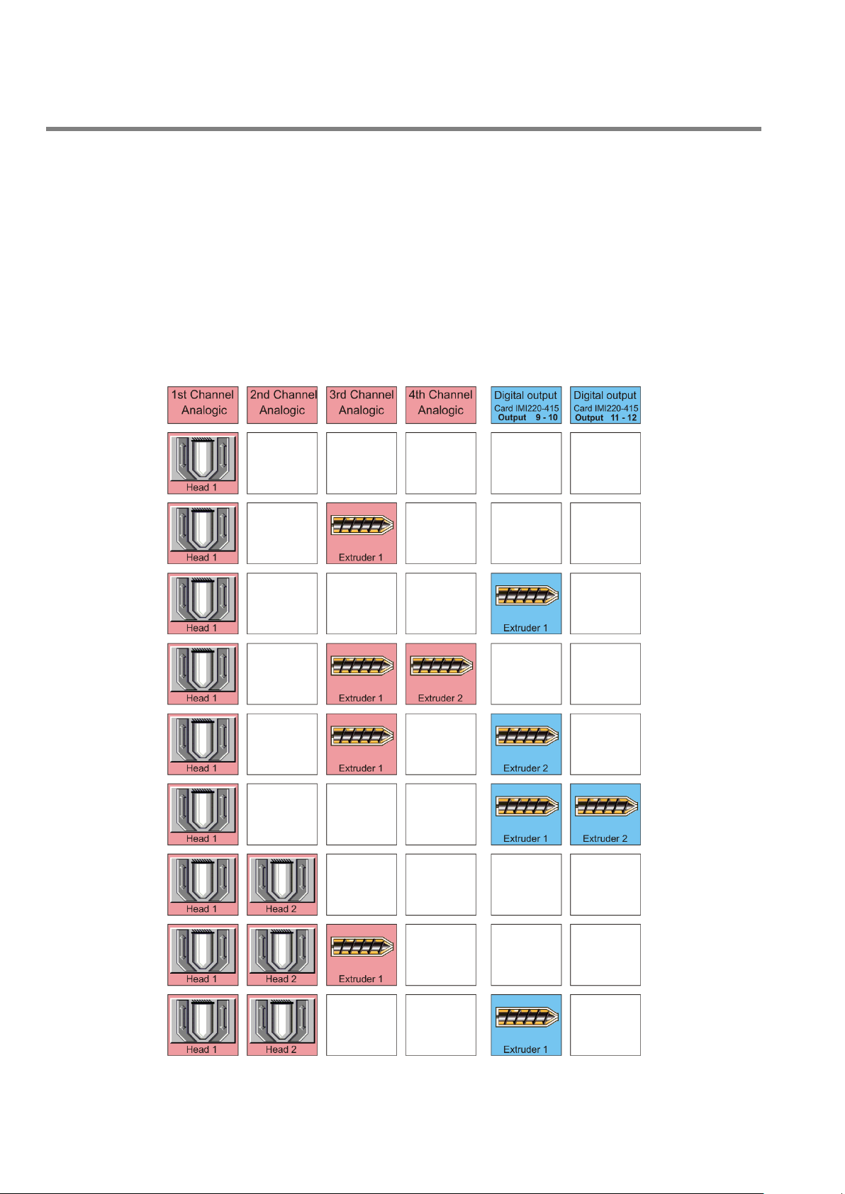
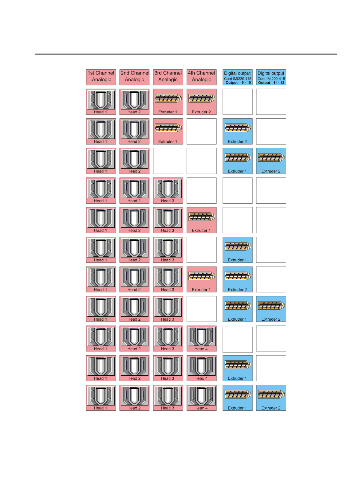
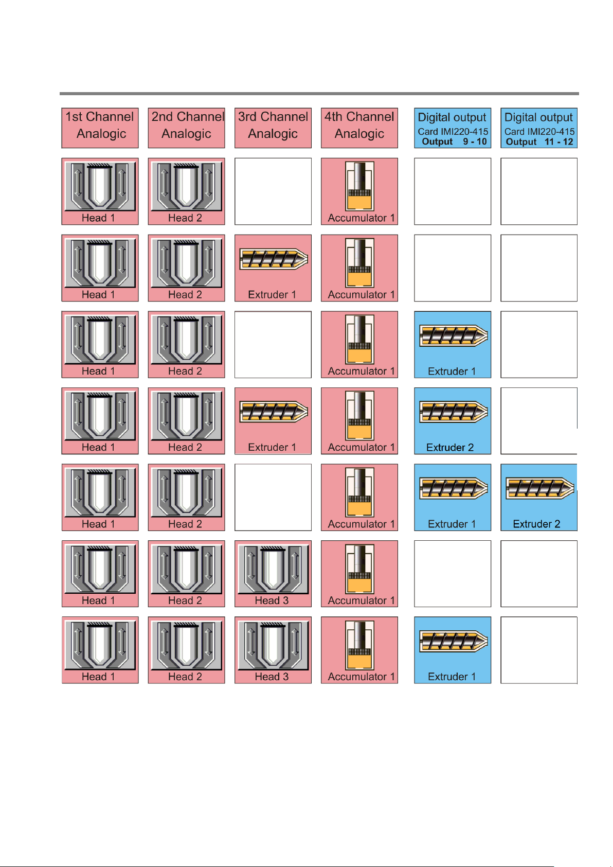
2.5.6 Machine configuration.
Parison Controller can be configured to run in:
continuous extrusion with independent profiles
in continuous extrusion with unique profile
with accumulator position
time accumulator.
In the following figures it is possible to evaluate all the configurations supported by PARISON CONTROLLER (as
continuous extrusion or position accumulator).
2.5.7 Continuous Extrusion or Time Accumulator.
Figure 18
20 MAN145-UM-D01A-EN Moog Italiana srl - Bergamo
Page 21
PARISON CONTROLLER
moog
Figure 19
In continuous extrusion with independent profiles there are 2 command sets to make regulators 1 and 2
running independently from regulators 3 and 4. In this way it is possible to have a completely synchronized
operation of both parts. Regulators 1 and 2 will run with digital input START1 and regulators 3 and 4 will run with
digital input START2.
Moog Italiana srl - Bergamo MAN145-UM-D01A-EN 21
Page 22
PARISON CONTROLLER
moog
If a new start front is received before the current profile ends, this is interrupted and the next profile immediately
starts. If the new start front is received after the profile ends, the last point value is kept on output.
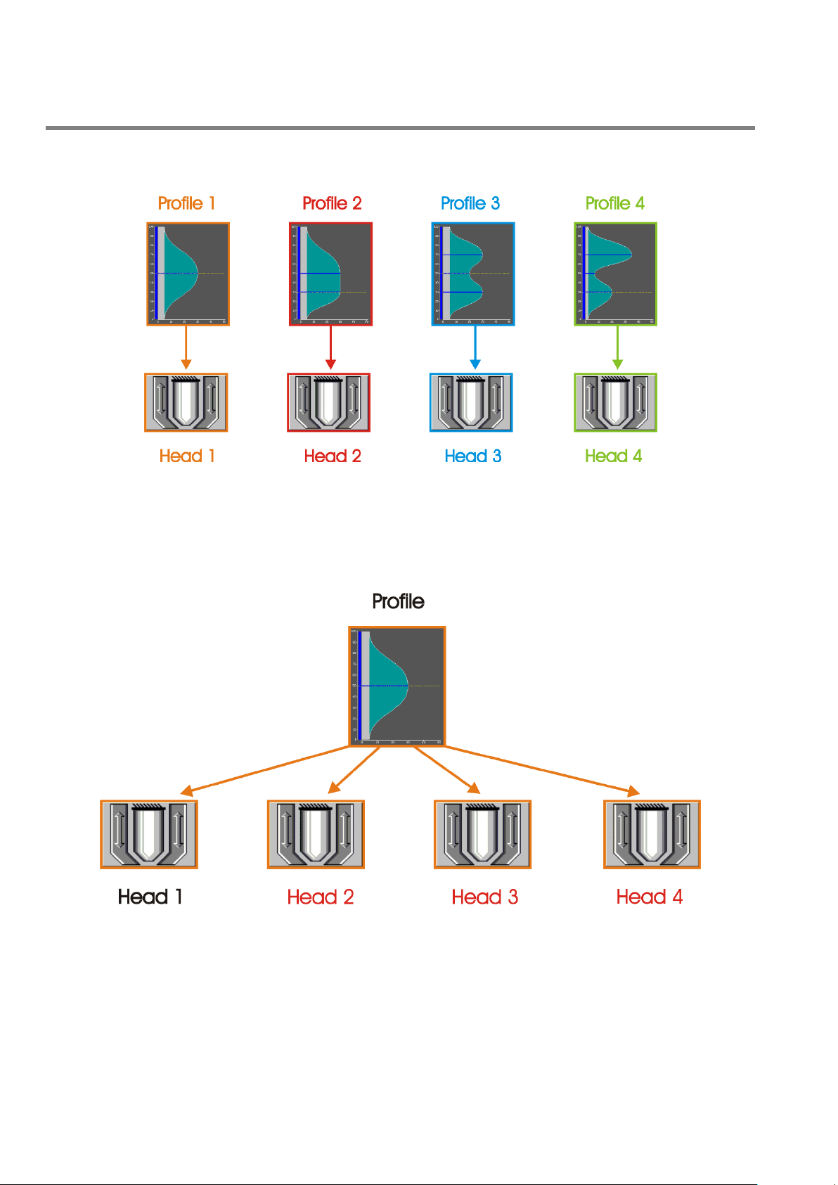
Figure 20
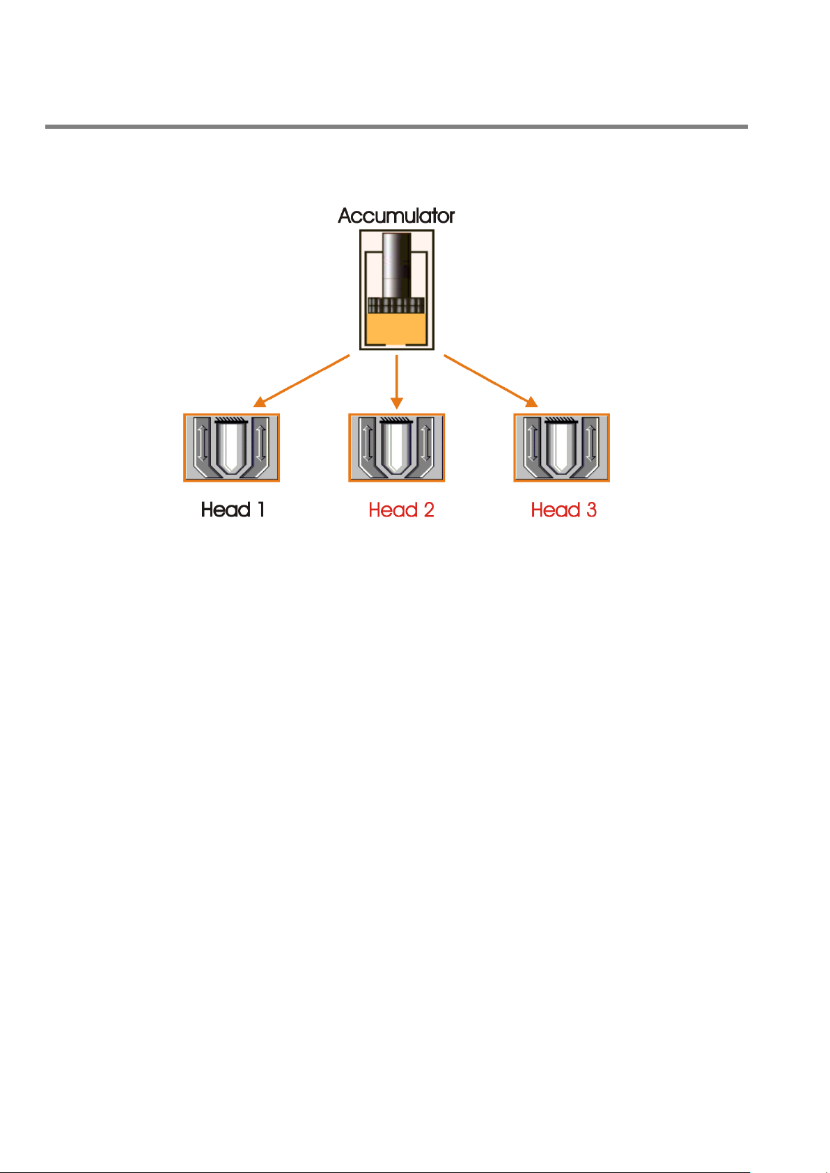
In continuous extrusion with unique profile there are 4 thickness regulators available (ranging from 1 to 4) and
one unique profile drives all of them. The profile issue for all the regulators is with digital input START1.
There is only one work page (Profile) and more setup page of setup for the calibration of the used heads.
In the work page it is possible to change the weight of the profile for every single head. The markers are active only
on head 1.
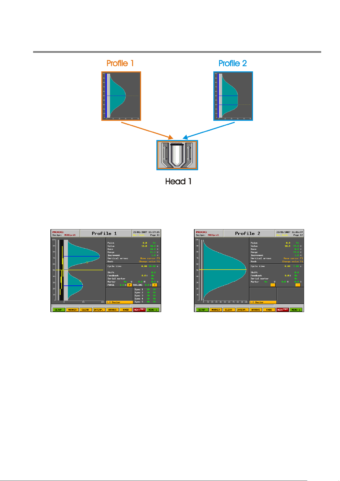
Figure 21
In continuous extrusion with unique profile and with only one head it is possible to enable the alternate
parison function.
Every profile has the start signal (Start 1 => Profile 1, Start 2 => Profile 2), the cycle time and the correction
independent.
22 MAN145-UM-D01A-EN Moog Italiana srl - Bergamo
Page 23
PARISON CONTROLLER
Figure 23
Figure 24
moog
Figure 22
Example alternate profile:
Profile 1 and Profile 2 work with output head 1 in alternate mode. The Profile 1 starts with Start group 1 and the
profile 2 starts with Start group 2.
Moog Italiana srl - Bergamo MAN145-UM-D01A-EN 23
Page 24
PARISON CONTROLLER
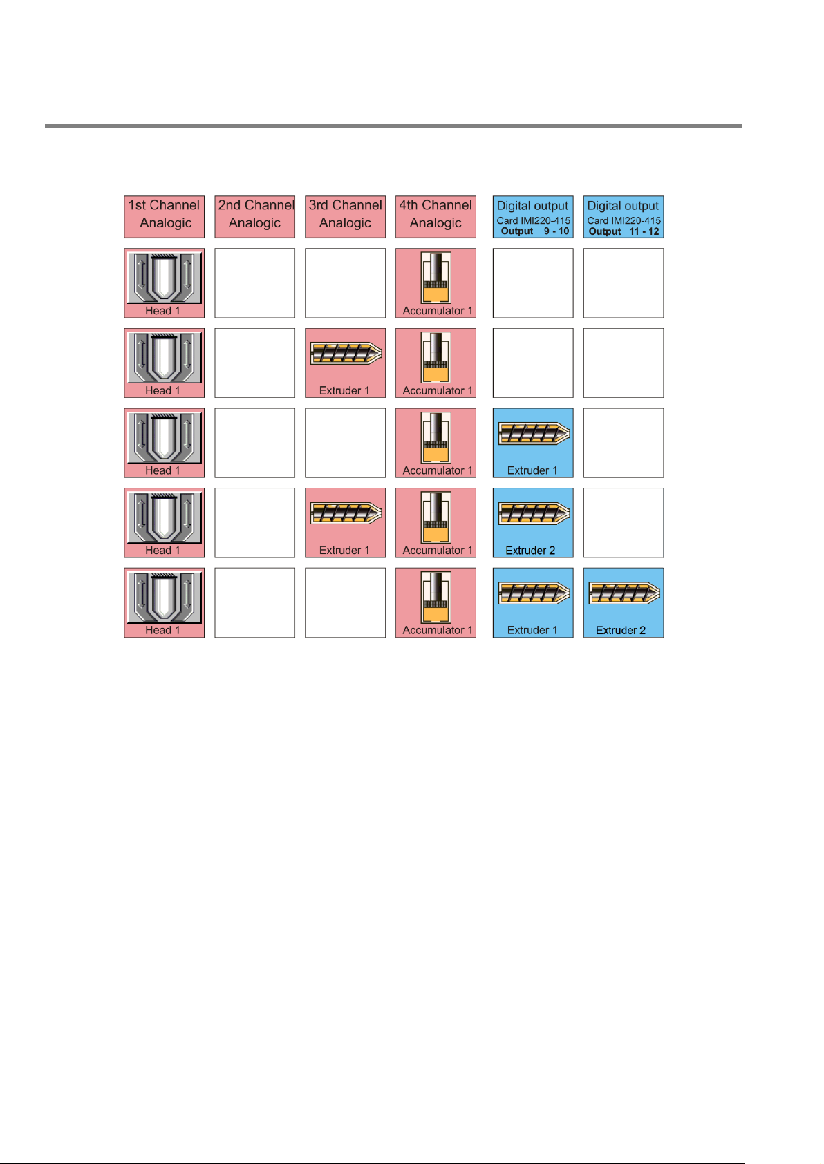
2.5.8 Position Accumulator.
moog
Figure 25
24 MAN145-UM-D01A-EN Moog Italiana srl - Bergamo
Page 25
PARISON CONTROLLER
moog
Figure 26
Moog Italiana srl - Bergamo MAN145-UM-D01A-EN 25
Page 26
PARISON CONTROLLER
moog
With accumulator position there are 3 position-dependent thickness regulators available (ranging from 1 to 3).
The thickness regulators follow the accumulator position. Thickness regulators work with independent profiles. The
accumulator extrusion is driven by the digital input START1.
Figure 27
With time accumulator there are 4 thickness regulators available (ranging from 1 to 4). The thickness regulators
are time-base driven by a single start signal (START1). Thickness regulators work with independent profiles.
Cycle time automatic correction not enabled: profile is generated by a fixed setpoint.
Cycle time automatic correction enabled: the time between rising edge of Start1 signal and its falling
edge it is measured; this time becomes the setpoint for the profile generation at next start.
Average correction enabled: carry out the average of 3 latest cycles. The average becomes the setpoint
for profile generation at next start.
If the falling edge of Start1 signal is received before the end of the current profile, the profile is interrupted. If the
falling edge is received after profile end, the setpoint holds the last point value.
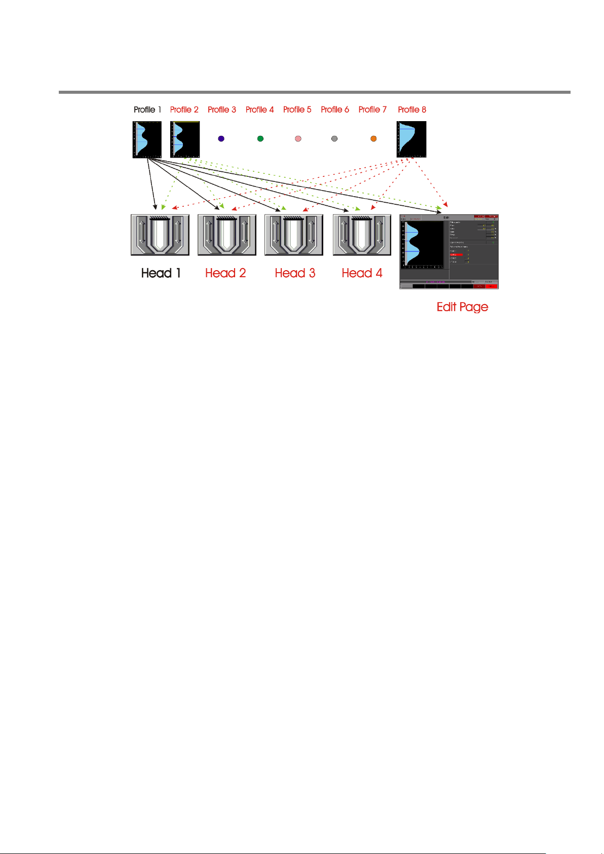
In every machine configuration type (except for alternate parison) it is possible to assign any profile to each head.
If the function Free Profiles Assignment is not enabled (see Setup Machine Page) the assignment of the profiles
is fixed (head 1 = profile 1; head 2 = profile 2, etc.).
26 MAN145-UM-D01A-EN Moog Italiana srl - Bergamo
Page 27
PARISON CONTROLLER
moog
Figure 28
If the function Free Profiles Assignment is enabled (full edit mode; see Setup Machine Page) it is possible to
assign to each head anyone of the 8 profiles available.
The 8 profiles can be displayed, modified and copied (if they are not already assigned to some head) in the Edit
page. In this page it is possible to know which profile each regulator is using.
2.5.9 Control Update Rate.
The close loop sampling time is normally 2 ms.
In continuous extrusion with only one head the control is faster (only 1 ms sampling time).
Moog Italiana srl - Bergamo MAN145-UM-D01A-EN 27
Page 28
PARISON CONTROLLER
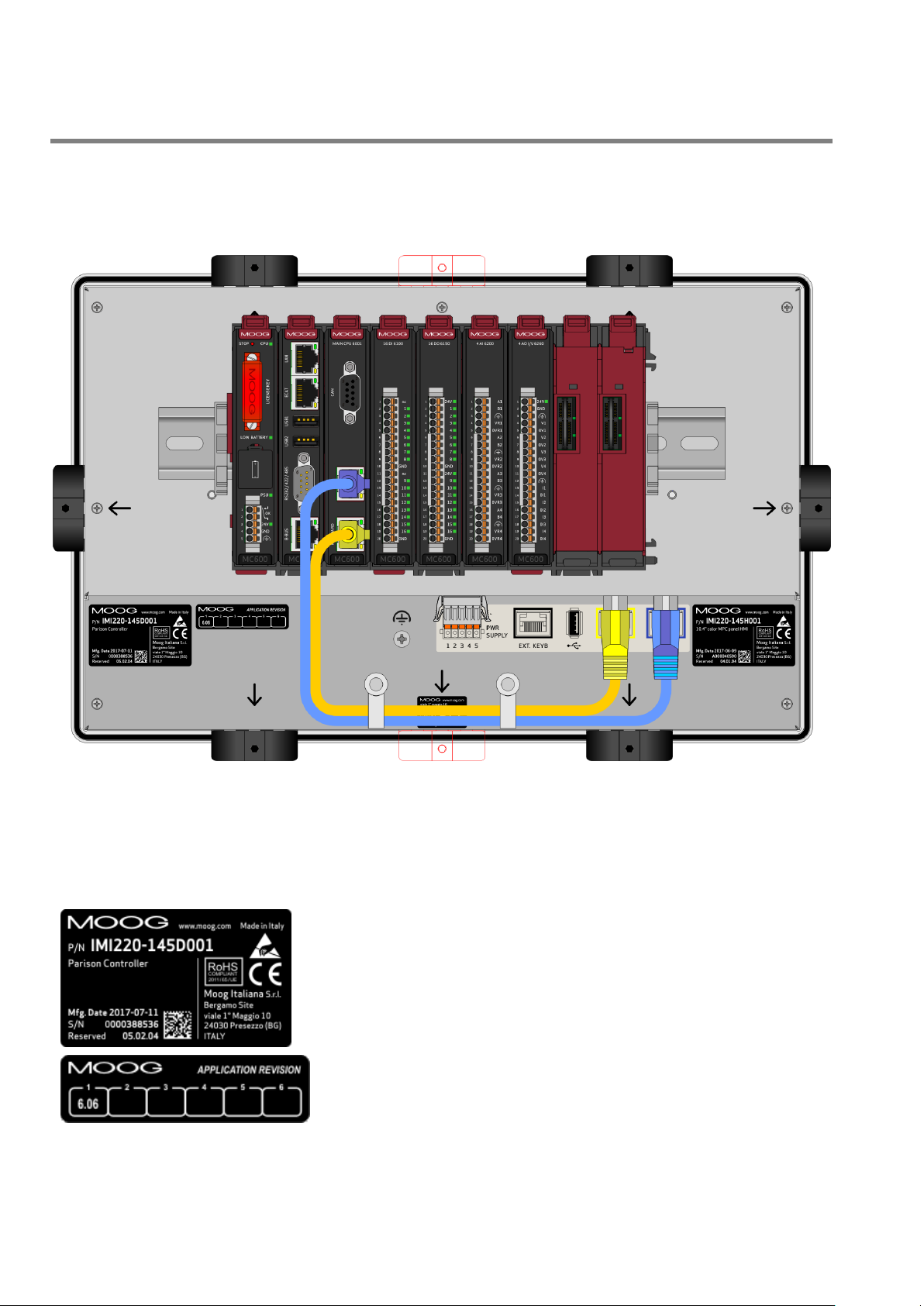
P/N: Ordering code (Product Code: 145; Release Level: D; hardware
equipment: 001).
Mfg. Date: Release date.
S/N: Serial number.
Reserved: Code reserved to the qualified personnel.
Application Revision
3 Hardware Description.
3.1 Parison Controller Rack based 600 Series (Rear).
moog
Figure 29
Place 1/2/3 Card IMI220-6001A001 (POWER SUPPLY – MAIN CPU – HMI DRIVER).
Place 4 Card IMI220-6100A001 (16 Digital Input card 24Vdc).
Place 5 Card IMI220-6150A001 (16 Digital Output 24V 0.5A card).
Place 6 Card IMI220-6200A001 (4 Analog Input 16 Bit).
Place 7 Card IMI220-6260A001 (4 Analog Output I/V 16 Bit).
28 MAN145-UM-D01A-EN Moog Italiana srl - Bergamo
Page 29
PARISON CONTROLLER
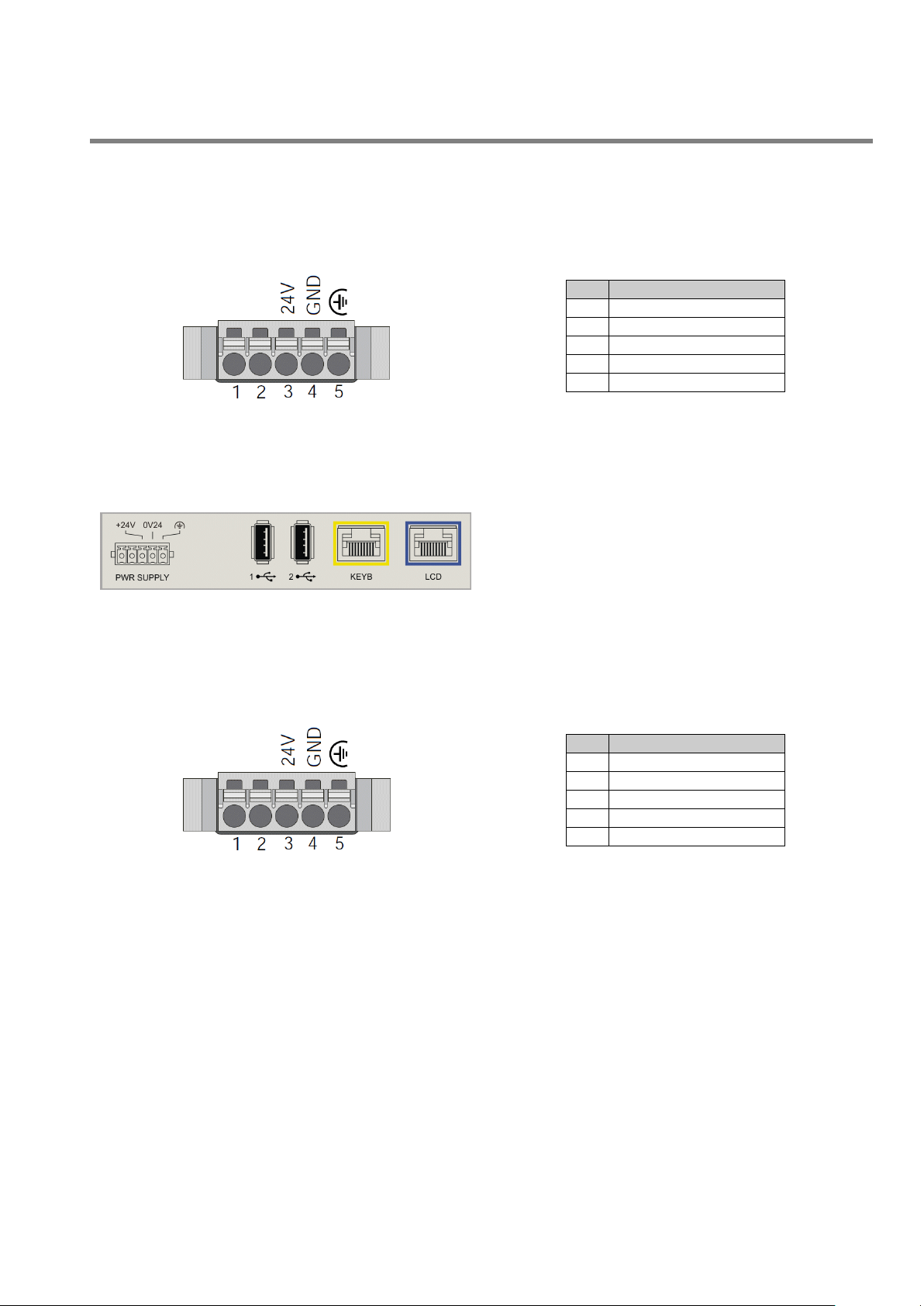
Figure 30
N°
Signal
1
OK Rely NO contact
2
OK Rely (Common)
3
+ 24V
4
GND
5
Earth
Figure 31
System label: Description of the position of the USB and
video connectors.
PWR SUPPLY: Power Supply of the display.
USB1: front USB device.
USB2: not to use
KEYB: LVDS keyboard connection
LCD: LVDS display connection
Figure 32
N°
Signal
1
Not used
2
Not used
3
+ 24V
4
0V24
5
GROUND
PLC Power Supply:.
moog
Display Power Supply:
Moog Italiana srl - Bergamo MAN145-UM-D01A-EN 29
Page 30
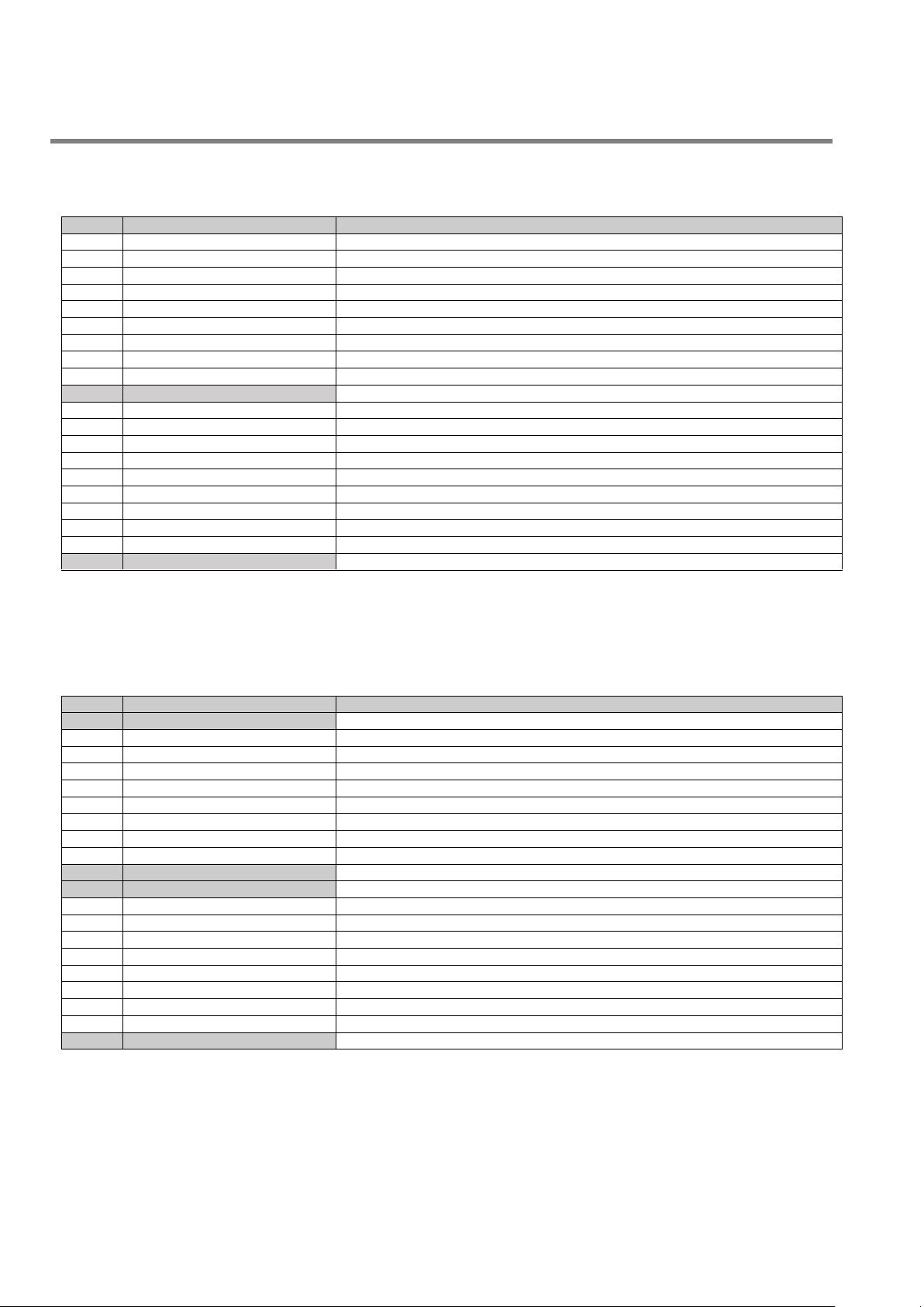
PARISON CONTROLLER
Pin n°
Name
Description
1
nc 2
Start profile group 1
Profile start signal for group 1 regulators
3
Photocell parison group 1
Measure signal of parison length for group 1 regulators
4
Mould ready group 1
Signal for mould ready to collect group 1 parison
5
Purge group 1
External enable for group 1 purge
6
Start profile group 2
Profile start signal for group 2 regulators
7
Photocell parison group 2
Measure signal of parison length for group 2 regulators
8
Mould ready group 2
Signal for mould ready to collect group 2 parison
9
Purge group 2
External enable of group 2 purge
10
GND
11
nc
12
Stand by die gap
Die gap closing signal during accumulation phases
13
Temperature OK
Operation enable of regulators and extruders
14
Emergency
Operation enable
15
Presence alarm in machine
Indication of machine alarm pieces
16
Machine in automatic
Indication of machine in automatic or manual mode
17
Piece discard
Decrease of produced pieces caused by a rejection
18
Not used.
19
Not used.
20
GND
Pin n°
Name
Description
1
+24V
Supply voltage +24V.
2
End filling
Indication of reached accumulator end of filling quota
3
End extrusion
Indication of reached end of extrusion quota
4
Synchronism 1
Sync command n°1 of first thickness regulator
5
Synchronism 2
Sync command n°2 of first thickness regulator
6
Synchronism 3
Sync command n°3 of first thickness regulator
7
Synchronism 4
Sync command n°4 of first thickness regulator
8
Synchronism 5
Sync command n°5 of first thickness regulator
9
Serial marker
Command of serial marker actuator
10
GND
Supply voltage 0V.
11
+24V
Supply voltage +24V.
12
Increment extruder 1
Increase command for extruder 1
13
Decrement extruder 1
Decrease command for extruder 1
14
Increment extruder 2
Increase command for extruder 2
15
Decrement extruder 2
Decrease command for extruder 2
16
Enable timer switch
Enable command from timer switch
17
End production
End of product signal
18
Alarm
Alarm signal
19
Head in calibration
Head number 1 in calibration mode
20
GND
Supply voltage 0V.
3.2 Digital Input (Card IMI220-6100A001).
moog
3.3 Digital Output (Card IMI220-6150A001).
30 MAN145-UM-D01A-EN Moog Italiana srl - Bergamo
Page 31

PARISON CONTROLLER
Pin n°
Name
Description
1
A1
Positive analog input 1
2
B1
Negative analog input 1
3
PE
Ground pin for connecting ground and shield
4
VR1
+10V reference voltage for sensors
5
0VR1
0V reference voltage return line
6
A2
Positive analog input 2
7
B2
Negative analog input 2
8
PE
Ground pin for connecting ground and shield
9
VR2
+10V reference voltage for sensors
10
0VR2
0V reference voltage return line
11
A3
Positive analog input 3
12
B3
Negative analog input 3
13
PE
Ground pin for connecting ground and shield
14
VR3
+10V reference voltage for sensors
15
0VR3
0V reference voltage return line
16
A4
Positive analog input 4
17
B4
Negative analog input 4
18
PE
Ground pin for connecting ground and shield
19
VR4
+10V reference voltage for sensors
20
0VR4
0V reference voltage return line
Pin n°
Name
Description
1
24V
Positive analog input 1
2
GND
Negative analog input 1
3
PE
Ground pin for connecting ground and shield
4
V1
Analog output (voltage) 1
5
0V1
Analog output (voltage) return line 1
6
V2
Analog output (voltage) 2
7
0V2
Analog output (voltage) return line 2
8
V3
Analog output (voltage) 3
9
0V3
Analog output (voltage) return line 3
10
V4
Analog output (voltage) 4
11
0V4
Analog output (voltage) return line 4
12
PE
Ground pin for connecting ground and shield
13
I1
Analog output (current) 1
14
0I1
Analog output (current) return line 1
15
I2
Analog output (current) 2
16
0I2
Analog output (current) return line 2
17
I3
Analog output (current) 3
18
0I3
Analog output (current) return line 3
19
I4
Analog output (current) 4
20
0I4
Analog output (current) return line 4
3.4 Analog Input (Card IMI220-6200A001).
moog
3.5 Analog Output (Card IMI220-6260A001).
Moog Italiana srl - Bergamo MAN145-UM-D01A-EN 31
Page 32

PARISON CONTROLLER
Figure 33
Figure 34
Figure 35
moog
3.6 Wiring.
In the following pages some wiring examples with different types of parison controls are presented.
For the actuators which are equipped with a position current feedback signal of 4÷20 mA it has been indicated to
use a buffer to convert the current signal into a voltage signal. This is required because the analog input card 4 AI
6200 accepts only voltage signals.
It is possible to use a 500 Ω resistor to convert the current signal into a voltage signal that can be connected to the
analog input card. The following drawings help to clarify this application; note that one side of the resistor is
connected to input A and to the current signal coming from the actuator; the other side of the resistor is connected
to input B and to the signal zero volt.
For those actuators which have the same wiring arrangement but a voltage feedback instead of a
current feedback, it is possible to directly route the signal to the A pin of the relevant analog input
and connect pin B to the signal common as depicted in the following picture.
32 MAN145-UM-D01A-EN Moog Italiana srl - Bergamo
Page 33

PARISON CONTROLLER
Wiring for Digital Input/Output and Power Supply.
moog
Moog Italiana srl - Bergamo MAN145-UM-D01A-EN 33
Page 34

PARISON CONTROLLER
moog
Wiring for continuous extrusion with Moog servo actuator cable L081-016 (Integrated Electronic Type 15Vdc).
34 MAN145-UM-D01A-EN Moog Italiana srl - Bergamo
Page 35

PARISON CONTROLLER
moog
Wiring for continuous extrusion with Moog servo actuator cable L081-018 (Integrated Electronic Type 15Vdc).
Moog Italiana srl - Bergamo MAN145-UM-D01A-EN 35
Page 36

PARISON CONTROLLER
moog
Wiring for continuous extrusion with Moog servo actuator in current (Integrated Electronic Type 24Vdc).
36 MAN145-UM-D01A-EN Moog Italiana srl - Bergamo
Page 37

PARISON CONTROLLER
moog
Wiring for accumulator head with Moog servo actuator (Integrated Electronic Type 15Vdc).
Moog Italiana srl - Bergamo MAN145-UM-D01A-EN 37
Page 38

PARISON CONTROLLER
moog
Wiring for accumulator head with Moog servo actuator (Integrated Electronic Type 24Vdc).
38 MAN145-UM-D01A-EN Moog Italiana srl - Bergamo
Page 39

PARISON CONTROLLER
Wiring for continuous extrusion with customer actuator.
moog
Moog Italiana srl - Bergamo MAN145-UM-D01A-EN 39
Page 40

PARISON CONTROLLER
Wiring for accumulator head with customer actuator.
moog
40 MAN145-UM-D01A-EN Moog Italiana srl - Bergamo
Page 41

PARISON CONTROLLER
Wiring for continuous extrusion with Moog actuator (With DCDT Type).
moog
Moog Italiana srl - Bergamo MAN145-UM-D01A-EN 41
Page 42

PARISON CONTROLLER
Wiring for accumulator head with Moog actuator (With DCDT Type).
moog
42 MAN145-UM-D01A-EN Moog Italiana srl - Bergamo
Page 43

PARISON CONTROLLER
Wiring for continuous extrusion Moog EMA L875-XXX.
moog
Moog Italiana srl - Bergamo MAN145-UM-D01A-EN 43
Page 44

PARISON CONTROLLER
UNIT: mm
3.7 Terminal measures.
moog
Figure 36
44 MAN145-UM-D01A-EN Moog Italiana srl - Bergamo
Page 45

PARISON CONTROLLER
UNIT: mm
moog
Figure 37
Moog Italiana srl - Bergamo MAN145-UM-D01A-EN 45
Page 46

PARISON CONTROLLER
UNIT: mm
moog
Figure 38
46 MAN145-UM-D01A-EN Moog Italiana srl - Bergamo
Page 47

PARISON CONTROLLER
Figure 40
With Technician or Responsible password, the fields date,
actual time and data format will appear. To change any
value double-click the appropriate field and set the desired
value.
4 Description of the Screen Functions.
4.1 Main Menu.
moog
Main Menu: Main part of the Main Menu.
Access: From all pages with key F8.
Use: Change page to submenus using keys F1 to F8.
4.1.1 Password.
The password is a 4 character string; to insert the value:
double-click on the field and then insert the string with the relative keyboard
press Ent key to confirm the entry
press Esc key to abandon the insertion
4.1.2 Date Change.
For example if you want to set 03/08/2017 (dd/mm/yy), you type 03082017 (as numeric fields) followed by Ent key.
Similarly for the actual time: if you want to set 08:50:00, you type 085000 followed by Ent key.
Is possible to select between European data format (dd/mm/yy) or American data format (mm/dd/yy).
Moog Italiana srl - Bergamo MAN145-UM-D01A-EN 47
Figure 39
Page 48

PARISON CONTROLLER
Work head 1: Setup and display the Parison profiles.
Profile 1: Setup and display the alternate profiles.
Work head 2: Setup and display the Parison profiles.
Profile 2: Setup and display the alternate profiles.
Work head 3: Setup and display the Parison profiles.
Work head 4: Setup and display the Parison profiles.
Accumulator: Setup and display the Accumulator profile.
Work extruder 1: Setup and display the extruder.
Work extruder 2: Setup and display the extruder.
Alarms: Display alarms from PLC and from system.
Main Menu 2: Go to main menu 2.
4.1.3 Function Keys.
moog
48 MAN145-UM-D01A-EN Moog Italiana srl - Bergamo
Page 49

PARISON CONTROLLER
Edit: Editing the Parison profiles. It is possible to access the Edit page only if on
Setup Machine Page the Free Profiles Assignment ON.
Timer Switch: Setup the time of turning on and off the heating. It is possible to
access the Timer Switch page only if on Setup Machine Page you set
Management timer switch ON.
Production: Production data management. It is possible to access the Production
page only if on Setup Machine Page you set Production Control ON.
Recipe: Recipe management. It is possible to access the recipe page only if you
insert a Technician or Responsible password.
All Profiles: open the all profiles page where it is possible to view all active
profiles at a glance.
Input / Output: Monitor status input/output digital/analogical data.
4.2 Main Menu 2.
moog
Main Menu 2: Second part of the Main Menu.
Access: From Main Menu with key F8.
Use: Enter submenus.
4.2.1 Function Keys.
Figure 41
Moog Italiana srl - Bergamo MAN145-UM-D01A-EN 49
Page 50

PARISON CONTROLLER
Setup Machine: Setup the machine configuration. It is possible to access the
machine setup page only if you insert a password of Technician level.
Main Menu: Go to main menu 1.
moog
50 MAN145-UM-D01A-EN Moog Italiana srl - Bergamo
Page 51

PARISON CONTROLLER
It is possible to select one of the following
types of machine (in manual mode):
Continuous extrusion to independent
profile.
Continuous extrusion to unique profile.
With accumulator position.
With time accumulator.
4.3 Machine Setup.
moog
Figure 42
Machine Setup: Configure the machine.
Access: From Main Menu 2 with key F7.
Use: Configure the PARISON CONTROLLER according to the typology of the machine that will be
connected.
ATTENTION: to modify some parameters the digital input number 13 (machine in
automatic mode) has to be OFF. This operation is permitted only if the machine is in
manual mode.
4.3.1 Function of the machine.
Moog Italiana srl - Bergamo MAN145-UM-D01A-EN 51
Page 52

PARISON CONTROLLER
Figure 43
Number of heads: Select(in manual mode) how many heads are
connected (range 1 ÷ 4).
Number of extruders: Select (in manual mode) how many extruders
have to be managed by the controller. (0 to 2).
Number points profile: Select (in manual mode) how many points
the Parison profile wants (range 10 - 400 points). The change of the
points number of the profile could show some anomalies in the
visualization of the profile shape. It is necessary to reset the old
profiles and draw the new one (see the reference table).
Task Time 1 ms
Cycle time
> 0.4 sec
0.3 0.4 sec
0.2 0.3 sec
0.1 0.2 sec
Suggested points
400
300
200
100
Task Time 2 ms
Cycle time
> 0.8 sec
0.6 0.8 sec
0.4 0.6 sec
0.2 0.4 sec
Suggested points
400
300
200
100
moog
4.3.2 General setup of the machine.
Technician password: Write the password for Technician level. This Password is permanently saved. With this
level password is possible to modify every field.
Responsible password: Write the password for Responsible level. This Password is permanently saved. With
this level password is possible to modify every field but all the setup pages are disabled.
Current language: Select the visualization language. The following languages are available:
English, Italian, German, French, Spanish, Portuguese, Danish, Russian, Turkish, Greek, Chinese, Japanese.
Number synchronisms: Number of synchronisms. The controller can manage up to 5 sync points driving a specific
output. With the Continuous extrusion mode the syncs are edited in the Work Head page where Profile 1 is active.
With Accumulator position mode they are edited in the Accumulator page.
Mode sync 1 (or 2/3/4/5): (visible in Accumulator position mode) Select synchronism mode: Filling, Extrusion or
both. This parameter sets the accumulator movement in which the sync is active.
Default interpolation: Select default interpolation used when you insert a new master in the profile.
4.3.3 How to chose the correct points number:
Task Time is 1 ms if 1 head is active in continuous extrusion mode. Task Time is 2 ms in all other cases.
Reference table:
Points = Cycle time (s) / Task time (s)
52 MAN145-UM-D01A-EN Moog Italiana srl - Bergamo
Page 53

PARISON CONTROLLER
Figure 44
Alternate parison: (visible in Continuous extrusion to unique
profile mode and with only one head) Decides if the head has to
work with one or two alternated profiles.
Production Control: Enable or disable the visualization of the
Production page.
Visualize serial marker: Enable or disable the visualization of
the serial marker in head 1 work page.
Visualize marker: Enable or disable the visualization of the
markers in all heads pages.
Vis. horizontal ruler: Enable the visualization of the horizontal
ruler in the profile pages.
Vis. vertical ruler: Enable the visualization of the vertical ruler
in the profile pages.
Figure 45
Output N°x type: is possible to select (in
manual mode) the command output type,
Voltage or Current, for each channel. The
yellow labels on the right show what
actuator is connected to each channel.
moog
4.3.4 Machine Settings.
Vis. Feedback as a line: Enable the feedback visualization as a line in the profile pages. It is recommended with
cycles times shorter than 5 seconds.
Autorange profile: Enable auto-range profile to resize the horizontal rulers. (Range 0 - 25, 0 - 50, 0 - 100).
Free profiles assignment: (not visible when Alternate parison is enabled) Enable the visualization of the Edit
Profile page and the possibility to assign different profiles to each head (from 1 to 8).
Management timer switch: Enable or disable the visualization of the Timer page.
Visualize shift: To enable the function in case of use of the shift on the profile. It allows a better interpolation
between the first and the last point of the profile.
Brightness: Manage the TFT Brightness (seven levels:
Time functioning: Counter indicating how long the Parison Controller has been ON.
4.3.5 Output selection.
to increase, - to decrease).
+
With current command is possible to select the current range:
- Current Command +/- 7.5 mA.
- Current Command +/- 15 mA.
- Current Command +/- 30 mA.
- Current Command +/- 50 mA.
- Current Command +/- 75 mA.
- Current Command +/- 100 mA.
4.3.6 Languages.
It is possible to select one of the following languages:
English, Italian, German, French, Spanish, Portuguese, Danish, Russian, Turkish, Greek, Chinese, Japanese.
Moog Italiana srl - Bergamo MAN145-UM-D01A-EN 53
Page 54

PARISON CONTROLLER
moog
54 MAN145-UM-D01A-EN Moog Italiana srl - Bergamo
Page 55

PARISON CONTROLLER
SET MAC2: Select Setup page 2.
PREV | NEXT: Fast selection of the next or previous Setup page. The next and
previous Setup Page depends on the current machine configuration.
MENU 2: Select Main menu, page 2.
4.3.7 Function Keys.
moog
Moog Italiana srl - Bergamo MAN145-UM-D01A-EN 55
Page 56

PARISON CONTROLLER
Enable digital output during
calibration
Enable digital output number 16 (output is ON when head 1 is in calibration
mode)
Die gap management with
continuous extrusion
Enable the die gap function also in continuous extrusion. To reach the die gap
position is necessary to use digital input number 9: Stand by die gap (connect
digital output 2 and digital input 9 to reach the die gap position at the end of
extrusion)
Auto change page with
alternate parison
Enable the automatic selection of profile 1 and profile 2 pages. With Start 1
signal, profile 1 page is selected; with Start 2 signal, profile 2 page is selected
Touch sound
Enable the beep at every keypress on the display
Base/Range/Purge level
access
Set the password level required to activate the purge function
Enable PWDS
Configure the selected control channel as a Partial Wall Thickness Distribution
System (PWDS); the relevant axis is used to control a deformable die used to
obtain more material on certain portions of the extruded material and less on
the others
PWDS in mm
The deformation of the die will be expressed in mm rather than in percentage
Calibration
When the deformation is expressed in mm these fields are used to set the
admissible range that will be available in the work page
moog
4.4 Machine Setup 2.
Machine setup: Configure the machine.
Access: From Setup Machine with key F2.
Use: Configure the PARISON CONTROLLER according to the typology of the machine that will be
connected.
4.4.1 Machine settings - page 2.
Figure 46
56 MAN145-UM-D01A-EN Moog Italiana srl - Bergamo
Page 57

PARISON CONTROLLER
SET MAC: Select Setup page 1
PREV | NEXT: Fast selection of the next or previous Setup page. The next
and previous Setup pages depend on the current machine configuration
MENU 2: Select Main menu, page 2.
4.4.2 Function Keys.
moog
Moog Italiana srl - Bergamo MAN145-UM-D01A-EN 57
Page 58

PARISON CONTROLLER
Figure 48
From left to right:
Vertical ruler: (white) If enabled in Setup Machine Page (Vis. vertical ruler).
From 1 to max 400 points to navigate.
Horizontal ruler: (white) If enabled in Setup Machine Page (Vis. horizontal
ruler). Percentage scale from 1 to 100 % max. Default number is 100, but if
Autorange profile in Setup Machine Page is enabled, the horizontal ruler is
resized.
Serial Marker: Vertical logical state diagram showing the serial marker
activation along the profile.
Synchronisms: (only if enabled): 5 vertical lines that display 5 synchronisms
signals defined by a couple of start and stop points.
Bargraph: Shows the working point of selected head as feedback. In case of
extrusion (or time based mode) the bargraph will be red and start at point 1. In
case of Filling the bargraph will be blue and start at max point.
4.5 Work Head n / Profile n.
moog
Figure 47
Work Head n: Parison page n° (n° = 1 to 4).
Access: From Main Menu with key F1...F4.
Use: Edit parison profile and parameters for the die opening. Each regulator uses an analog input to
read the mandrel actual position and an analog output to drive the mandrel positioning actuator.
4.5.1 Profile Editor.
The line is yellow, if working during Extrusion, green if working during Filling and red if working both in Extrusion
and Filling. Synchronisms are visible only on profile 1.
4.5.2 Profile parameters.
58 MAN145-UM-D01A-EN Moog Italiana srl - Bergamo
Page 59

PARISON CONTROLLER
Figure 49
Profile associate: (Only if Free profiles assignment is
enabled) Profile number associated to the head.
Point: Shows in yellow the actual point during the movement
in accordance with the red bar graph on the right side of the
screen. In green the position of the cursor in the Parison field.
Value can be changed from 1 to 400 to set the cursor position.
Figure 50
Cycle time: Displays in yellow the Parison
cycle time during the movement and in green
the Parison cycle time in seconds.
Weight: Change the weight of the profile.
Shift: It is possible to indicate by how many
points (N) to shift the profile. Once the last
point of the profile is reached, the setpoint
continues from point 1 until point N-1.
moog
Value: Shows in yellow the desired percentage setting and in green the value of the point where the cursor is in
the Parison field. By changing this value (0 to 100% max) it is possible to add a new setpoint or modify the existing
one at the cursor position.
Base: Displays the minimum profile value. By changing the base it is possible to shift the whole profile. Range: 0%
to Max limit (Profile). The max limit added to the range must be less or equal to 100% (base + range <= 100).
Range: Displays the profile range as difference between maximum and minimum value. By changing the range it
is possible to resize the entire profile. Range: 1% to Max limit ( Weight). The max limit added to the base must be
inferior or equal to 100% (base + range <= 100).
Increment: This is the amount by which the setpoint value is incremented or decremented when editing the profile
at the cursor position.
Vertical arrows: Shows the vertical arrows active function (chapter 2.5.4).
Knob: Shows the entry knob active function (chapter 2.5.4).
4.5.3 Cycle parameters.
Feedback: If activated, it allows to see the actual value of the profile measured by the transducer (in red) beside
the theoretical one. Head: Allows to choose the feedback of the desired head in case of unique profile. The yellow
field shows the actual value in percentage.
Serial marker: Enable (YES) or disable (NO) the serial marker in the profile. Enable the digital output command
of serial marker actuator on card IMI220-415A001 to identify the points of the profile on the final product.
Marker: Enable (YES) or disable (NO) all markers in the profile. It is possible to setup the markers on each profile.
For each profile you can setup different values of marker length in points and width in percentage.
W: Marker Width (in points). Value corresponding to the working gap with the preceding and following points related
to the position where the Marker has been set.
H: Marker Height (in percentage). Value corresponding to the working gap with the opening and closing points
related to the position where at the Marker has been set.
Moog Italiana srl - Bergamo MAN145-UM-D01A-EN 59
Page 60

PARISON CONTROLLER
Figure 51
In the example two markers are placed at points 30 and 70. The red line shows
the feedback.
With W (Width) = 5 points and H (Height) = 3%, the value will be increased up
to 3% from point 25 (30 - 5), reset to the programmed value at point 30 and
decreased by 3% until point 35 (30 + 5).
PURGE: Purge referred to this head. It is possible to indicate a setpoint,
expressed in %, for the head opening. Purge is driven by a special function key
or digital input. Purge through digital input is possible only if the function is
configured and the machine is in manual mode. This command activated during
the issuing of a profile becomes active only at the end of the same profile. The
buttons that control this function are toggle type.
TOOLING: Tooling referred to this Head. It is possible to indicate a setpoint,
expressed in %, for the tooling function. Tooling is driven through a special
function key. This command activated during the issuing of a profile becomes
active only at the end of the same profile. The buttons that control this function
are toggle type.
Die gap position: Available with accumulator or continuous
extrusion. If enabled it sets the die gap position of the head.
Figure 52
Weight: With unique profile it allows to add an additional
weight on every single head. (not visible in profile).
moog
4.5.4 Die gap
4.5.5 Weight
60 MAN145-UM-D01A-EN Moog Italiana srl - Bergamo
Page 61

PARISON CONTROLLER
Figure 53
Bezier: Interpolation between two masters: the
interpolation type visualized corresponds to the area
where the cursor is placed. The smooth parameter is
included between 0.5 and 2.0 with step 0.1.
Figure 54
Linear: Interpolation between two masters: the
interpolation type visualized corresponds to the area
where the cursor is placed.
4.5.6 Interpolation.
moog
Moog Italiana srl - Bergamo MAN145-UM-D01A-EN 61
Page 62

PARISON CONTROLLER
Figure 55
Flat: Interpolation between two masters: the
interpolation type visualized corresponds to the area
where the cursor is placed.
Figure 56
Parabolic 1: (parabola with tangent 0 on start point)
Interpolation between two masters: the interpolation
type visualized corresponds to the area where the
cursor is placed.
Figure 57
Parabolic 2: (parabola with tangent 0 on end point)
Interpolation between two masters: the interpolation
type visualized corresponds to the area where the
cursor is placed.
moog
62 MAN145-UM-D01A-EN Moog Italiana srl - Bergamo
Page 63

PARISON CONTROLLER
Figure 58
Synchronisms: Only if enabled in Machine setup page. Each synchronism is
defined by a pair of start and stop points along the profile (1…400 max). They are
represented also by vertical lines on the left of the profile-edit-field.
Figure 59
Figure 60
The Profile editor is similar
to the normal head’s one
except that the zero point
of the horizontal axis is not
always on the left side but
depends on the calibration
settings
In Figure 59 the PWDS is
setup in % and the zero
point is in the middle
In Figure 60 the PWDS is
setup in mm and is
calibrated from -8 to +2
mm.
moog
4.5.7 Synchronisms.
4.5.8 Work Head n for PWDS Control
Any channel can be dedicated to control a Partial Wall Thickness System (PWDS). When a control channel is
configured for this function, some of the parameters available for a normal parison head are meaningless and
therefore are not visible both in the setup and working pages.
In the working page the following parameters are not present:
Base
Weight
Head
Tooling
Die gap position
Moog Italiana srl - Bergamo MAN145-UM-D01A-EN 63
Page 64
PARISON CONTROLLER
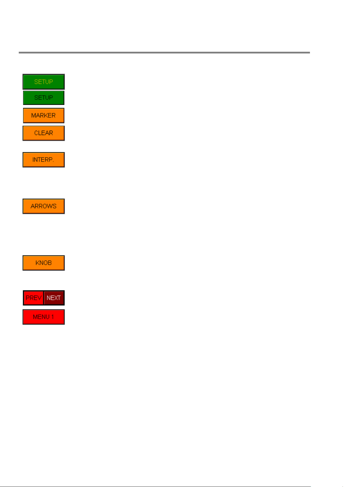
SETUP: (yellow) Disable. (black) Enter in the setup page.
MARKER: Add or remove a marker on the profile.
CLEAR + SHIFT: Clear all the profile points. Before creating a new profile (only in this
case) it's necessary to use this function to ensure a correct initialization of the new
profile.
INTERPOLATION: Change the interpolation. Changes the interpolation type between
the two masters where the cursor is placed. There are 5 possibilities: Bezier, Linear,
Flat, Parabolic 1, Parabolic 2. The default interpolation is the one that has been set in
the Machine setup page.
ARROWS: Selects how the Vertical Arrows have to work:
- Move cursor: move the cursor up and down.
- Next master: move the cursor on the master.
- Drag master: drag the master up and down.
- Next marker: move the cursor on the marker.
- Drag marker: drag the marker up and down.
- Drag SM: drag the Serial Marker up and down.
- Selects profile: select a part of the profile.
- Drag selection: drag the selection up and down.
KNOB: Selects how the Knob has to work:
- Change value: rotate the knob to change the value.
- Change base: rotate the knob to change the base.
- Change range: rotate the knob to change the range.
- Change interp: rotate the knob to change the interpolation.
- Change smooth: rotate the knob to change the Bezier smoothness value.
- Setup SM: rotate the knob to setup the Serial Marker.
NEXT: Fast selection of the next or previous work head page.
MENU 1: Go to main menu 1 page.
4.5.9 Function Keys.
moog
64 MAN145-UM-D01A-EN Moog Italiana srl - Bergamo
Page 65

PARISON CONTROLLER
4.6 Head Setup.
moog
Figure 61
Setup 1| Head n: Setup 1 | Head n. page (n. = 1 to 4).
Access: From Work Page n. with key F1.
Use: For the calibration and the setup of the head parameters.
The regulator can operate in closed loop (with no-intelligent actuators) or in open loop (with intelligent actuators
that operate with an on-board closed loop). The input value is calibrated in range 0% - 100.00% through the
definition of upper stroke voltage and lower stroke voltage. In case of intelligent actuators the calibration points are
set to 0 mV and 10000 mV which are the correct values if no calibration is required.
In the normal polarity an increasing output command moves the actuator downwards (rod extracts)
and the feedback input value increases too.
It is possible to correct the polarity of both the command and feedback with specific settings in the setup page.
The procedure to check the wirings is described in the next chapter: “Check wirings”.
Moog Italiana srl - Bergamo MAN145-UM-D01A-EN 65
Page 66

PARISON CONTROLLER
moog
4.6.1 Check wirings.
To check the correct wiring:
Choose open loop calibration.
With the UP/DOWN keys verify the correct movement: if the UP key is pressed, the moving part has to
move up, if the DOWN key is pressed the moving part has to move down.
o If the movement is OK :
Check the bar graphs movement (yellow and blue). If bar graphs are moving in the same
direction, also the input is OK and it is possible to perform the calibration in close loop.
If the bar graphs are moving in opposite directions, reverse the input polarity by inverting
the parameter Inv. input in the head setup page
o If the movement is not OK :
Reverse the input polarity by inverting the parameter Inv. output in the head setup page
After this, the movement should be correct. If bar graphs are moving in the same
direction, also the input is OK and it is possible to perform the calibration in close loop.
If the bar graphs are moving in opposite directions, reverse the input polarity by inverting
the parameter Inv. input in the head setup page
66 MAN145-UM-D01A-EN Moog Italiana srl - Bergamo
Page 67

PARISON CONTROLLER
Select open loop
calibration
Verify UP/DOWN
movement
Moveme
Verify bar graphs
Same
direction
It is possible
Change the input
variable
Change the
Put YES the
variable
Verify bar graphs
movement
Same
direction
Yes
No
No
Yes
Yes
No
moog
To better understand how to perform a correct calibration see the following flow chart.
output inversion
output wiring
movement
wiring or put YES
the input inversion
the calibration
in close loop
Moog Italiana srl - Bergamo MAN145-UM-D01A-EN 67
The parameter used to reverse the input polarity is only used during the close loop calibration. In
work mode the polarity is derived by the values of "Vup" and "Vdown" and the polarity reversal
parameter is ignored
Page 68

PARISON CONTROLLER
Work: in work mode the position loop is
closed, the machine works normally. No
calibration is active. The calibration points
are those written in the fields V.Up and
V.Down.
Open loop: in open loop mode it is
possible to move the head with UP or
DOWN keys; speed can be set in the
Inc.up and Inc.down parameters. When
the head is in an end-of-stroke, set V.Up.
or V.Down values by pressing the relevant
CONFIRM key.
Manual calibration: in manual
calibration mode the loop is closed and it
is possible to move the head UP or
DOWN till the key is pressed. When the
key is released the head maintains the
current position (Position control).
Figure 62
Automatic calibration: in automatic
calibration mode select Start to YES: the
head will move to the two end-of-strokes
and record the relevant V.Up and
V.Down values. When the automatic
calibration is finished the controller
switches to Work mode.
4.6.2 Calibration.
Select the head operation mode only in manual mode (digital input 13 OFF):
To perform the calibration digital input 13 (machine in automatic mode) has to be OFF. The
calibration is permitted only if the machine is in manual mode.
moog
Start: to automatically start the procedure that moves the actuator down, intercepts the mechanical end-of-stroke,
moves the actuator up, intercepts the mechanical end-of-stroke and saves the corresponding voltage values.
Inv. Output: if you select YES you reverse the analog Output.
Inv. Input: if you select YES you reverse the analog Input only during the calibration. See the chapter “4.6.1 Check
wirings” to understand the use of this parameter.
Out: it is possible to select the output command between voltage and current. (the same setting is available in the
machine setup page)
Inc. Up / Inc. Down: With calibration in open loop these variables correspond to the acceleration value of the
output command (expressed in mV/s or mA/s). It's the ramp increment or decrement value on the analog Output.
Inc. Up determines the slope ramp toward max. output. Inc. Down determines the slope ramp toward min. output.
With manual and automatic calibration these variables correspond to the velocity increment (%/s) to move the head
in close loop.
With an intelligent actuator these variables correspond to the acceleration value (mV/s) of the ramps that determine
the head position.
68 MAN145-UM-D01A-EN Moog Italiana srl - Bergamo
Page 69

PARISON CONTROLLER
Figure 63
V. Up and V. Down: In these fields the minimum and the maximum values
are visualized in mV relevant to the head total stroke. It is possible to modify
manually these values.
Figure 64
Die type: Select the die type with the knob
then press SET to confirm:
Convergent.
Divergent.
moog
MANUAL OPEN LOOP CALIBRATION WITH NO-INTELLIGENT ACTUATORS:
The input calibration can be made in manually open loop state. The purpose can be input calibration or manual
movement. Through manual commands it is possible to issue an output voltage that moves the actuator up or
down. The operator can visually check that the mechanical limits have been reached and confirms them. Output
command during manual motion ramps up while buttons are pressed and stay fixed when released. The output
command is expressed in % of maximum value, while the ramp is expressed in mV per second.
MANUAL OPEN LOOP CALIBRATION WITH INTELLIGENT ACTUATORS:
Through manual commands it is possible manage two kinds of ramps: from 0 to max and from max to 0. Output
command during manual motion ramps up while buttons are pressed and stay fixed when released.
MANUAL CLOSE LOOP CALIBRATION WITH NO-INTELLIGENT ACTUATORS:
The input calibration can be made manually in closed loop. The system generates a position setpoint (expressed
in %) and holds it in close loop. Through manual commands it is possible to change the position setpoint causing
the actuator to move up and down. The operator visually acknowledges when a mechanical limit has been reached
and confirms. The position setpoint is set by generating ramp signals increasing in % per second.
MANUAL CLOSED LOOP CALIBRATION WITH INTELLIGENT ACTUATORS:
It automatically generates the ramps with the pressure of the UP or DOWN buttons. The movement is interrupted
with a new pressure of the same button.
AUTOMATIC CALIBRATION WITH NO-INTELLIGENT ACTUATORS:
The input calibration can be made automatically in closed loop. By keeping the regulator in loop it is possible to
automatically start the procedure that moves the actuator down, intercepts the mechanical end-of-stroke, moves
the actuator up, intercepts the mechanical end-of-stroke and saves the corresponding voltage values. Change of
position setpoint is made by setting up two ramp values in % per second.
AUTOMATIC CALIBRATION WITH INTELLIGENT ACTUATORS:
Starting the procedure generates a ramp from 0 to max. to move the head down. At the end of this phase after 3
seconds it generates a ramp from max. to 0 to move the head up. It automatically saves the input values.
4.6.3 Die type.
It is possible to indicate if the actuator moves the mandrel or the die and if the mandrel is convergent or divergent.
This univocally identifies if the zero position is when the actuator is at upper or lower end-point.
Mobile part: Select the mobile part with the knob then press SET to confirm:
D-D: Die type Divergent and mobile part Die.
C-D: Die type Convergent and mobile part Die.
D-M: Die type Divergent and mobile part Mandrel.
C-M: Die type Convergent and mobile part Mandrel.
Moog Italiana srl - Bergamo MAN145-UM-D01A-EN 69
Page 70

PARISON CONTROLLER
Figure 65
Correction enable: Enable the time correction.
WITH CONTINUOUS EXTRUSION: The time between two next
rising edges of Start signal becomes the reference for the profile
generation at next start.
If average correction is enabled, the average of the 3 last cycles
will be calculated. This value becomes the reference for the profile
generation at next start.
moog
4.6.4 Run parameters.
WITH TIME ACCUMULATOR: If cycle time automatic correction is not enabled, the profile generation is made with
a fixed timing. If cycle time automatic correction is enabled, the time between the rising edge of Start1 signal and
its falling edge is measured. This value becomes the reference for profile generation at next start.
Correction with average: Enable the time correction with average. (over last 4 cycles)
Maximum correction: Set the maximum correction to the cycle time. If the value is 0, the last cycle time is applied
to the next start. After correction the cycle time will be not less than 1/3 of the value set in the work head page.
Purge with input: Enable the activation of the purge function with a digital input (only when machine is in manual
mode).
Auto run: Enable the Auto run. (Only for demonstration). When the regulator auto run is active the profile
generation starts immediately after the previous profile is complete without waiting for a new start signal. Cycle
time correction will be ignored.
Stand by die gap: (Only in accumulator position mode) Select how to reach the die gap position (with digital input
or after end extrusion) or if to stay at the last profile point:
Digital input: Digital input 9 called “Stand by die gap” requests the head to move to the die gap
position after the programmed delay to start the filling.
End extrusion: In case of no external “Stand by die gap” signal it is possible to trigger the
movement with the end of extrusion signal after the programmed delay.
Last point: At the end of extrusion the head holds the last profile point and after the delay it
After this action the die holds the position until next start signal.
Delay die gap: (Only in accumulator position mode or in continuous extrusion if enabled) Delay before starting the
filling.
Die gap position: (Only in accumulator position mode or in continuous extrusion if enabled) Head position after
profile is completed.
4.6.5 Regulator parameters.
It is possible to indicate a minimum time to complete the total mandrel stroke. This time determines the maximum
ramp time of the position command signal. It is possible to compensate the valves dead band and to delay
movement starting.
starts the filling.
70 MAN145-UM-D01A-EN Moog Italiana srl - Bergamo
Page 71

PARISON CONTROLLER
Figure 66
Maximum output slope: Minimum time for the maximum
excursion of the head (from all open to all close). It allows us to
define a ramp for the maximum variation of the analog output. In
this way very fast movements of the head are not allowed. If the
time is 0 every movement is free. With a value of 1 second, for
example, the position command increment will be 20000 mV/s.
Every movement will be performed according to the calculated
ramp.
moog
Feedback actuator: Select if the actuator has a feedback transducer (intelligent actuator).
Vout Min/Vout Max: (only if feedback actuator is YES). It allows to choose between which values the intelligent
actuators has to work. The default parameters are 0 / 10000 [mV]
KP gain: Proportional gain. Range: 0...10000.
KI gain: Integral gain. Range: 0...10000.
KD gain: Derivative gain. Range: 0...10000.
Divisor: It allows to choose the divisor of the formula to calculate the output command: the divisor allows to insert
the parameters PID with different resolutions.
OUT = (KP * DEV + KI * (integral add DEV) + KD * (derivate DEV)) / DIV
DEV=Actual Value[%] - Setpoint[%]
Calibration Mode 100%= 20000 mV
Work Mode 100%= Vup – Vdown
Dead band positive: Value added to the output already calculated by the PID controller to compensate the positive
dead band. Range: 0...+5000 mV or max value mA.
Dead band negative: Value subtracted from the output already calculated by the PID controller to compensate the
negative dead band. Range: 0...+5000 mV or max value mA.
Start delay time: delay time on movement starting (1). The second time (2) refers to the profile 2 with alternate
profiles.
4.6.6 Head Setup for PWDS
The setup page for channels managing the PWDS function is almost identical as the one for normal parison
control: the only difference is that the configuration of the die type, with the four big icons in the middle of the
page, is not present; for the same reason also the function keys F3 to F6 are gray.
Also the second Start delay time, the one used in case of alternated profiles, is not present
Moog Italiana srl - Bergamo MAN145-UM-D01A-EN 71
Page 72

PARISON CONTROLLER
HEAD 1: Select Head page.
SETUP 2: Select Setup 2 Head 1 page.
D-D: Select die type Divergent and mobile part Die.
C-D: Select die type Convergent and mobile part Die.
D-M: Select die type Divergent and mobile part Mandrel.
C-M: Select die type Convergent and mobile part Mandrel.
NEXT: Fast choose of the next or previous setup head pages .
MENU 1: Select Menu 1 page.
4.6.7 Function Keys.
moog
72 MAN145-UM-D01A-EN Moog Italiana srl - Bergamo
Page 73

PARISON CONTROLLER
Figure 68
Control length profile (Only with accumulator position): Enable
the length control on the profile.
Point for control: Set the reference point for the control.
Maximum error: Maximum allowed error calculated between the
programmed point and the point triggered by the photocell signal.
4.7 Head Setup 2.
moog
Figure 67
Setup 2 Head 1: Setup 2 Head 1 page.
Access: From Setup1 Head1 Page with key F7. (only with acc. position)
Use: With accumulator position it is possible to activate the parison length control. Comparison
between photocell signal and programmed point.
At photocell signal, the currently issued point is detected and compared with a reference value. The difference
between the two values (in points) is the error. If the error is lower than Minimum error, no correction is made. If
the error is greater than Maximum error it is possible to decide whether making the maximum correction or making
no correction at all. If the error is between minimum and maximum a proportional correction is calculated. The
correction is made by changing the additional weight value on the regulator (Trim). A single photocell drives all the
regulators.
4.7.1 Control length parameters.
Minimum error: Minimum allowed error.
Maximum correction: correction to be applied if the calculated error is greater of the maximum allowed error.
Correction type: no correction or maximum correction if the error is greater of the maximum allowed error.
When the error is smaller than the Minimum error no correction is made. When the error is included between the
Minimum error and the Maximum error the correction is proportioned to the Maximum correction.
Moog Italiana srl - Bergamo MAN145-UM-D01A-EN 73
Page 74

PARISON CONTROLLER
Figure 70
Actual point: current point
Photocell point: working point triggered by the photocell signal
Error: difference between the control point and photocell point.
Correction: calculated value of correction that will be added to the
weight planned on the heads.
Feedback: real actual value.
moog
When the error is greater than Maximum error the correction can be of two types:
Correction type = Maximum (The correction is the Maximum correction).
Correction type = Nothing (No correction is made).
4.7.2 Correction.
Figure 69
74 MAN145-UM-D01A-EN Moog Italiana srl - Bergamo
Page 75

PARISON CONTROLLER
HEAD 1: Select Head page.
SETUP 1: Select Setup 1 Head 1 page.
NEXT: Fast selection of the next or previous setup pages .
MENU 1: Select Menu 1 page.
4.7.3 Function Keys.
moog
Moog Italiana srl - Bergamo MAN145-UM-D01A-EN 75
Page 76

PARISON CONTROLLER
4.8 Accumulator.
moog
Figure 71
Accumulator: Parison page in accumulator position mode.
Access: From Main Menu with key F4.
Use: Set accumulator stroke and edit profile and parameters for injection speed control. A regulator in
accumulation mode requires that the accumulator management is setup on the fourth channel.
The setpoint generated for the thickness regulator depends on the accumulator position in
injection phase related to the total injection stroke.
With start signal (digital input number 1) begins the push out up to the position of end extrusion (even if the signal
start is not more active). The output command is related to the planned profile.
With end extrusion if start is OFF the output command goes to a clamp value that it can be adjustable on setup
page. The output stays in this condition even if the actual profile point goes back below the last point. The heads
position stays in close loop on the last point.
With end extrusion if start is ON the output command stays at the value of the last point. The output stays in this
condition even if the actual profile point goes back below the last point. The heads position follows backward its
profile in close loop if accumulator position goes back.
With die gap signal (start signal has to be OFF) the output command goes to filling value (only negative) and is
latched. This value is adjustable on setup page. The heads go on die gap position or stay on the last point. With
the next start the output goes to the push out value.
In Manual mode (digital input number 13 OFF) the push out is active only if start is ON. If start is OFF the output
command goes to filling value.
With Digital Accumulator (no output command) when the start1 signal goes ON a red bar graph visualized the
accumulator position during the external push out. With end extrusion the digital output number 2 goes ON. With
die gap signal (digital input number 9) or end extrusion signal (see setup 1 head x page chapter 4.6.4) a blue bar
graph visualized the filling and the digital output of end extrusion will go OFF if accumulator position is different
from end extrusion position. When the accumulator position reaches the end of filling, the digital output number 1
goes ON.
76 MAN145-UM-D01A-EN Moog Italiana srl - Bergamo
Page 77

PARISON CONTROLLER
Figure 72
From left to right:
Vertical ruler: (white) From 1 to max 400 helps to navigate.
Horizontal ruler: (white) From 1 to max 100 %.
Serial Marker: Vertical logical state diagram that shows the state along the
profile.
Synchronisms: (only if enabled): 5 vertical lines, displays 5 synchronisms
signals defined by a couple of start and stop points. The line is yellow, if
working during Extrusion, green if working during Filling and red if working
both in Extrusion and Filling. Synchronisms are visible only on profile 1.
Bar graph: shows the working point of selected head as feedback. In case
of extrusion (or time based mode) the bar graph will be red and start at point
1. In case of filling (only accumulator mode) it is blue and starts at point max
400 (from top to bottom).
Figure 73
Point: The yellow value shows the actual point during the
movement; it follows the red bar graph on the right side of the
parison field. The green value shows the position of the cursor in the
parison field. Set this value (1 to 400 max) to change the cursor
position.
Value: The yellow value shows the actual feedback in %. The green
value shows in % the setpoint of the cursor point. By changing this
value it is possible to add a new setpoint or modify an existing one.
4.8.1 Profile Editor.
moog
4.8.2 Profile parameters.
Increment: This is the increment / decrement that changes the setpoint of the cursor position in the parison field.
Base: Displays the minimum profile value. By changing the base it is possible to shift the whole profile. Range: 0%
to Max limit (Profile). The max limit added to the range must be inferior or equal to 100% (base + range <= 100).
Range: Displays the profile range as difference between maximum and minimum value. By changing the profile it
is possible to resize the entire profile. Range: 1% to Max limit ( Weight). The max limit added to the base must be
inferior or equal to 100% (base + range <= 100).
Moog Italiana srl - Bergamo MAN145-UM-D01A-EN 77
Page 78

PARISON CONTROLLER
Figure 74
Push out time: Active only if in Setup Accumulator Page the Time
control extrusion is ON. (yellow) Actual cycle time. (green) Cycle
time extrusion.
End of filling: End of filling expressed in percentage.
moog
4.8.3 Accumulator parameters.
Volume of filling: Volume of filling expressed in percentage.
End of extrusion: End of extrusion expressed in percentage.
Volume of filling is always equal to the difference between End of filling and End of extrusion.
Figure 75
In accordance with the Setting and Priority parameters set in the setup page, these three parameters can be
modified in the following ways:
Setting: Free:
Priority: End filling - The priority parameter End filling is fixed when you change Volume of filling.
Priority: End extrusion - The priority parameter End extrusion is fixed while the other parameter End filling
changes when you change Volume of filling.
Setting: End extr. / Volume:
End filling is always fixed. It's possible to change only End extruder and Volume of filling.
Setting: End filling / Volume:
End extruder is always fixed. It's possible to change only End filling and Volume of filling.
Setting: End filling / Extr.:
Volume of filling is always fixed. It's possible to change only End extruder and End filling.
The analogical input referred to 100% (V. Full) has to be greater than the analogical input referred
to 0% (V. Empty).
78 MAN145-UM-D01A-EN Moog Italiana srl - Bergamo
Page 79

PARISON CONTROLLER
Figure 76
Real Position: real accumulator position.
This soft key selects the Accumulator popup window.
Figure 77
Accumulator popup window.
Output: output command value.
Push out time: extrusion time; if Time
control extrusion is enabled.
The red bar graph shows the real
accumulator position. (the value is the
yellow field with red background colour).
The two yellow fields without background
colour show the real end of filling and end
of extrusion values in case of the start
correction is enabled.
The led shows if the accumulator is in end
of filling position or in end of extrusion
position.
Last correction: last velocity correction if
enabled in the setup extruder page
Figure 78
Synchronisms: Only if enabled in machine setup page. Each synchronism is defined
by a pair of start and stop points along the profile (1…400 max). They are represented
also by vertical lines on the left of the profile-edit-field. They can be activated during
the extrusion, during the filling or in both movements.
4.8.4 Real Position.
moog
4.8.5 Synchronisms.
Moog Italiana srl - Bergamo MAN145-UM-D01A-EN 79
Page 80

PARISON CONTROLLER
SETUP: (yellow) Disable. (black) Select accumulator Setup page.
CLEAR: Clear all the profile.
INTERPOLATION: Change the interpolation.
COPY: Copy the profile placed on Head 1 in the extrusion speed profile of the
Accumulator.
NEXT: Select the next or previous page.
MENU 1: Select main menu 1.
4.8.6 Function Keys.
moog
80 MAN145-UM-D01A-EN Moog Italiana srl - Bergamo
Page 81
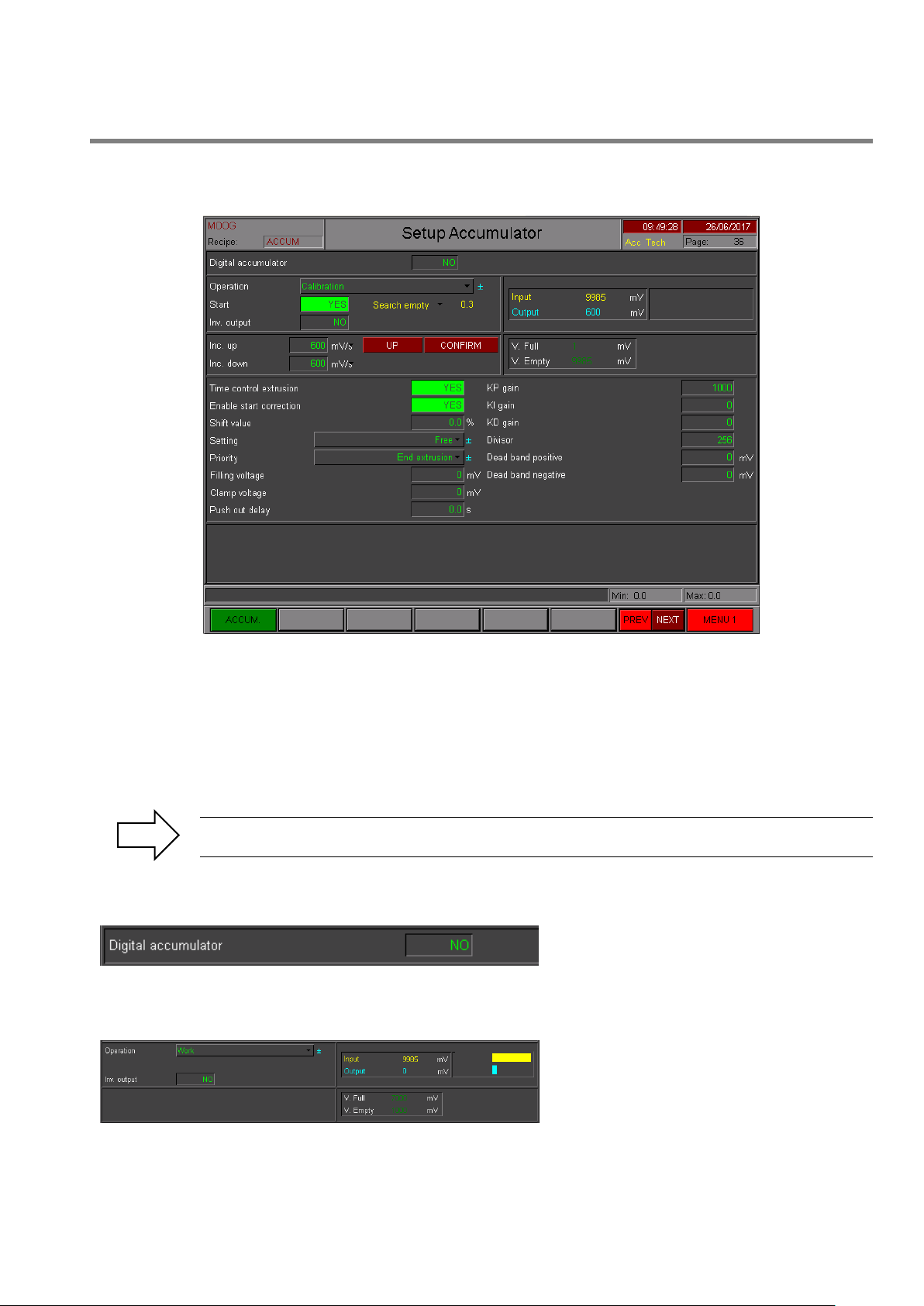
PARISON CONTROLLER
Digital Accumulator: to externally
manage the accumulator without the profile
speed control (if YES).
Work: in work mode the loop is closed, the
machine works normally. No calibration is
active. The calibration points are those
written in the fields V. Full and V. Empty.
4.9 Setup Accumulator.
moog
Figure 79
Setup Accumulator: Setup accumulator page in accumulator position mode.
Access: From Accumulator Page key F1.
Use: The input calibration should be made in this way: it is possible to indicate a voltage to be
applied on extrusion control output and activate empty accumulator calibration procedure.
The system automatically detects mechanical end-of-stroke, stores this value and
interrupts extrusion control. Using manual movements, the accumulator should be brought
to empty and full position and it is possible to manually confirm the two positions.
The analogical input referred to 100% (V. Full) has to be greater than the analogical input referred
to 0% (V. Empty).
4.9.1 Digital Accumulator.
The parison controller catches only the feedback position to manage the movement of the head.
Operation: Select the operation mode of the accumulator:
Moog Italiana srl - Bergamo MAN145-UM-D01A-EN 81
Page 82

PARISON CONTROLLER
Open loop: in open loop mode is possible to
move the accumulator down pushing DOWN
key. Pushing UP key it is possible to move the
accumulator Up because the output becomes
negative and the material moves up the
accumulator. When the accumulator is in
mechanical stroke you have to confirm the Full.
or Empty. values for the calibration.
Figure 80
Calibration: in calibration mode set Start to
YES and the accumulator automatically
searches for the empty position. Pushing UP
key it is possible to move the accumulator Up
because the output is negative and the material
moves up the accumulator. When the
accumulator is in position you have confirm the
values for the calibration.
Figure 81
V. Full and V. Empty: In these fields the full and the empty values are
visualized in mV.
Figure 82
Time control extrusion: Enable the control time during the
extrusion. If the control is set to NO the accumulator extrusion
speed is managed in open loop. In this case output voltage
depends on the profile assigned by accumulation. The profile
point to be output depends on the same accumulator position.
If the control is set to YES the accumulator extrusion speed is
managed in closed loop. In this case the profile is output in a
preset total time with a speed setpoint reflecting the profile.
moog
Inv. Output: Select YES to reverse the analog Output polarity.
Inc. Up / Inc. Down: these variables correspond to the acceleration value of the output command (expressed in
mV/s or mA/s). It is the ramp increment or decrement value on the analog Output. Inc. Up determines the slope
ramp towards +Max value. Inc. Down determines the slope ramp towards Min value.
The accumulator uses analog Input 4 to read the position and analog Output 4 to drive the extrusion (if the digital
accumulator is not enabled).
4.9.2 Run parameters.
The position closed loop performs the extrusion in order to follow the velocity profile.
Enable start correction: Enable the correction on the injection start position.
If this correction is NO, the filling quota passed to the head is calculated always from “end of filling” point to “end of
extrusion” point.
82 MAN145-UM-D01A-EN Moog Italiana srl - Bergamo
Page 83

PARISON CONTROLLER
moog
Figure 83
If this correction is YES is possible to chose a shift value to move the end extrusion position. If the difference
between the first value (STOP1) and the new value (STOP2) is lower than the shift value the correction is made.
The filling quota passed to the head is calculated from the new start point for a stroke equal to programmed injection
stroke.
Figure 84
Setting: Allows to choose the parameters to plan (see Figure 18).
It is possible to indicate whether the machine user can freely change the parameters defining machine filling and
extrusion or there are any limitations. It is possible to select among:
1. Free entry of end of filling point, volume, end of extrusion point.
2. Entry of end of extrusion point and volume.
3. Entry end of filling point and end of extrusion point.
4. Entry end of filling point and volume.
Limitations on data entry are not valid for service level access.
Priority: Allows to choose the parameter which has to be fixed in case of free setting (see Figure 18).
Filling voltage/current: Output voltage or current to let the filling (to help the valve during the filling). During the
filling it is possible to define fixed output command.
Clamp voltage/current: Output voltage or current when the end of extrusion is reached.
Push out delay: Delay before starting the push out.
Moog Italiana srl - Bergamo MAN145-UM-D01A-EN 83
Page 84

PARISON CONTROLLER
Figure 85
KP out 1: Proportional gain. Range: 0 to 10000.
KI out 1: Integral gain. Range: 0 to 10000.
KD out 1: Derivative gain. Range: 0 to 10000.
Divisor: It allows to choose the divisor of the formula. (see Setup
Head)
ACCUM.: Enter the Accumulator page.
NEXT: Enter the next Setup page.
MENU 1: Go to main menu 1.
moog
4.9.3 Regulator parameters.
Dead band positive: Value added to the output already calculated by the PID controller to eliminate the dead
band. Range: 0...+5000 mV or max value mA.
Dead band negative: Value subtracted from the output already calculated by the PID controller to eliminate the
dead band. Range: 0...+5000 mV or max value mA.
4.9.4 Function Keys.
84 MAN145-UM-D01A-EN Moog Italiana srl - Bergamo
Page 85

PARISON CONTROLLER
4.10 Work Extruder.
moog
Figure 86
Work Extruder n.: Work Extruder page n° (n° = 1 to 2).
Access: From Main Menu 1 key F5 (Extruder 1) or F6 (Extruder 2).
Use: It is possible to decide whether to use the extruder or not and which channel it should be associated to. It can
be associated to:
A thickness regulator in continuous extrusion.
A thickness regulator in time accumulation.
Accumulator.
It is possible to decide whether the extruder is driven by an analog or digital command. In case of analog command
the output voltage of a channel is the speed setpoint. In case of a digital command two digital outputs allow increase
or decrease of speed.
Extruder with analog command:
o It is possible to calibrate the input with: 0 speed voltage, maximum speed voltage, and maximum
speed. The speed is expressed in RPM.
o It is possible to calibrate the output with: maximum speed, voltage to reach maximum speed.
o These setpoints can be setup: speed to be reached, rise ramp in RMP/sec., descent ramp in
RPM/sec., minimum speed, maximum speed.
Extruder with digital command:
o You can setup the maximum time for digital output. (manual command or maximum velocity
control).
Moog Italiana srl - Bergamo MAN145-UM-D01A-EN 85
Page 86

PARISON CONTROLLER
Figure 87
Enable extruder: enable the output
command to control the extruder velocity.
The command velocity goes to 0 (if Enable
extruder is NO) or to the velocity setpoint by
a ramp.
Velocity setpoint: insert the velocity
setpoint. (visible with “Analog extruder”).
Velocity increment: (visible with “Digital extruder”) show the digital
output for increment.
Velocity decrement: (visible with “Digital extruder”) show the
digital output for decrement.
SETUP: (yellow) Disable. (black) Enter in the setup Extruder.
INC: (visible with “Digital extruder”) Velocity increment key.
DEC: (visible with “Digital extruder”) Velocity decrement key.
NEXT: Enter the next Setup page.
MENU 1: Go to main menu 1.
moog
4.10.1 Extruder command.
Minimum correction: with the velocity control if the error is lower to the planned minimum one (in point) it is
possible to apply a minimum correction however (in rpm).
Command velocity: Output command velocity. (visible with “Analogical extruder”).
Real velocity: Show the real velocity in rpm. (visible with “Analogical extruder”).
Point for control: (if enabled “Control length profile”) Show the point for control.
Point: (if enabled “Control length profile”) Current point from select head or point of accumulator extrusion.
Last correction: (with “Control length profile”) increment or decrement value with Analogical extruder.(rpm).
Last correction: (with “Control length profile”) increment or decrement value with Digital extruder.(ms)
4.10.2 Velocity increment and decrement.
4.10.3 Function Keys.
86 MAN145-UM-D01A-EN Moog Italiana srl - Bergamo
Page 87

PARISON CONTROLLER
Extruder type: to select the extruder type.
Figure 89
INPUT CALIBRATION
Voltage input: Analog input (input N° 3 for extruder 1, N° 4 for
extruder 2).
Minimum voltage: Minimum voltage in input related to 0 rpm
velocity.
4.11 Analog Extruder Setup.
moog
Figure 88
Extruder setup n.: Extruder Setup page n° (n° = 1 to 2).
Access: From Work Extruder Page 1 key F1.
Use: It is possible to setup the Extruder parameters.
4.11.1 Extruder Type.
Number combined head: Only with continuous extrusion and control length profile enabled. Select the number of
the Head associated to the Extruder (1 to 4).
4.11.2 Input Calibration.
Maximum voltage: Maximum voltage in input related to the maximum velocity.
Velocity with V max: Corresponding velocity with Maximum voltage.
Moog Italiana srl - Bergamo MAN145-UM-D01A-EN 87
Page 88

PARISON CONTROLLER
Figure 90
Voltage output: Analog voltage output. (output N° 3 for extruder
1, N° 4 for extruder 2).
Maximum velocity: Maximum velocity in rpm.
Voltage with max velocity: Voltage output to get the maximum
velocity.
Figure 91
Min vel. output limit: Minimum value for the velocity setpoint.
Max vel. output limit: Maximum value for the velocity setpoint.
moog
4.11.3 Output Calibration.
4.11.4 Velocity planned.
Increment slope: Increase slope for the ramp expressed in rpm/sec.
Decrement slope: Decrease slope for the ramp expressed in rpm/sec.
4.11.5 Velocity control.
It is possible to enable the extruder speed correction.
If the extruder is coupled to a continuous extrusion or time accumulation head, the error is calculated between
photocell and a programmed point or between photocell and die ready. The error is expressed in points.
If extruder speed is enabled and the extruder is coupled to the accumulator, the error is calculated between
end of filling signal and start injection signal. The error is expressed in percentage.
Speed correction is made in accordance with the following algorithm.
Errors lower than dead band values (in point with continuous extrusion, in percentage with accumulator) are not
considered (or is possible to apply a minimum correction).
An error between the maximum and minimum error (inside the window) is scaled on a maximum correction value
(in percentage or in millisecond). The correction is applied to extruder speed (with a ramp) or to the two digital
output (increment or decrement).
An error greater than the window can be ignored or cause the maximum correction.
88 MAN145-UM-D01A-EN Moog Italiana srl - Bergamo
Page 89

PARISON CONTROLLER
Figure 92
Extruder velocity control:
Enable or disable the control
length profile.
Control type: Select Photo/Mould
or Photo/Point control type only
with continuous extrusion. In
Photo/Mould mode, the control is
run by photocell digital input and
mould digital input.
EXTR.1: Enter the Extruder page.
NEXT: Enter the next or previous Setup page.
MENU 1: Go to main menu 1.
moog
In Photo/Point mode, the control, is run by photocell digital input and Point for control. With accumulator the control
is always made between end of filling and start injection. (see chapter 4.11.5 Velocity control)
Point for control: (the row is enabled when Photo/Point mode is selected) Point for the control (green). Yellow
point (on the left) is the point intercepted by the photocell. It is possible copy this value in point for control with the
confirm button. Yellow point (on the right) is the current point during the extrusion.
Minimum error: Minimum allowed error. (in point or in percentage)
Maximum error: Maximum allowed error. (in point or in percentage)
Maximum correction: Correction to be applied if the calculated error is greater of the maximum error. Maximum
correction applied at the velocity setpoint.
Correction type: Select from None to Maximum correction type. Correction - None: Output - None. Maximum
correction: use the Maximum correction value.
When the error is smaller of the Minimum error there is no correction.
When the error is inclusive between the Minimum error and the Maximum error the correction it is proportional
knowing the Maximum correction.
When the error is greater to the Maximum error the correction can be of two types:
Correction type = Maximum (The correction is the Maximum correction).
Correction type = Nothing (There is no correction). See Figure 15.
Delay time for photocell: Time before which the signal of the photocell has to be ignored. Only with continuous
extrusion.
Correction every n. cycles: Number of cycles after which make the correction.
Error number for warning: Number of consecutive errors to visualize a warning message.
4.11.6 Function Keys.
Moog Italiana srl - Bergamo MAN145-UM-D01A-EN 89
Page 90

PARISON CONTROLLER
Extruder type: to select the digital
extruder.
Figure 94
Maximum duration inc\dec:
maximum duration in millisecond of
the increment or decrement.
4.12 Digital Extruder Setup.
moog
Figure 93
Extruder setup n.: Extruder Setup page n° (n° = 1 to 2).
Access: From Work Extruder Page 1 key F1.
Use: It is possible to setup the Extruder parameters.
Number combined head: Only with continuous extrusion and control length profile enabled select the number of
the Head associated to the Extruder (1 to 4).
Errors lower than dead band values (in point) are not considered.
An error between the maximum and minimum error (inside the window) is scaled on a maximum correction value
(in millisecond). The correction is applied to the inc\dec digital output (output 9\10 extruder 1, output 11\12 extruder
2).
An error greater than the window can be ignored or cause the maximum correction (maximum duration).
90 MAN145-UM-D01A-EN Moog Italiana srl - Bergamo
Page 91

PARISON CONTROLLER
Figure 95
See Analogical extruder setup.
EXTR.1: Enter the Extruder page.
NEXT: Enter the next or previous Setup page.
MENU 1: Go to main menu 1.
4.12.1 Function Keys.
moog
Moog Italiana srl - Bergamo MAN145-UM-D01A-EN 91
Page 92

PARISON CONTROLLER
Figure 97
Timer switch: Status for the timer switch.
Current day: Show the current day.
4.13 Timer Switch.
moog
Figure 96
Timer switch: Timer switch page.
Access: From Main Menu 2 with key F2 (when the page is enabled in the setup machine).
Use: This page is visualized only if in the Setup Machine Page the field Management timer switch is ON.
Manage Timer Switch for temperature control. The time switch allows defining, for each weekday, a time interval
defined by a start and a stop time. When the time indicated by the system falls within this interval the “time switch”
digital output is set on.
4.13.1 Enable Timer Switch.
92 MAN145-UM-D01A-EN Moog Italiana srl - Bergamo
Page 93

PARISON CONTROLLER
Figure 98
The input is enabled from Responsible
level.
Time ON: Insert the start time. Hours and
minutes for every day of the week.
Time OFF: Insert the stop time. Hours and
minutes for every day of the week.
MENU 2: Go to main menu 2.
4.13.2 Weekly start and stop time.
4.13.3 Function Keys
moog
Moog Italiana srl - Bergamo MAN145-UM-D01A-EN 93
Page 94

PARISON CONTROLLER
Figure 100
Start profile group 1: Digital Input number 1.
Photocell parison group 1: Digital Input number 2.
Mould ready group 1: Digital Input number 3.
Purge group 1: Digital Input number 4.
Start profile group 2: Digital Input number 5.
Photocell parison group 2: Digital Input number 6.
Mould ready group 2: Digital Input number 7.
Purge group 2: Digital Input number 8.
Stand by die gap: Digital Input number 9.
Temperature OK: Digital Input number 10.
Emergency: Digital Input number 11.
Presence alarm in machine: Digital Input number 12.
Machine in automatic: Digital Input number 13.
Piece discard: Digital Input number 14.
4.14 Input / Output.
moog
Figure 99
Input / Output: Menu for the System State pages.
Access: From Main Menu 2 with key F6.
Use: To view digital/analog inputs/outputs. I/O digital monitoring show ON/OFF status of all digital inputs and
outputs. I/O analog monitoring shows voltage of all inputs and outputs.
4.14.1 Digital Input.
94 MAN145-UM-D01A-EN Moog Italiana srl - Bergamo
Page 95

PARISON CONTROLLER
Figure 101
End filling: Digital Output number 1.
End extrusion: Digital Output number 2.
Synchronism 1: Digital Output number 3.
Synchronism 2: Digital Output number 4.
Synchronism 3: Digital Output number 5.
Synchronism 4: Digital Output number 6.
Synchronism 5: Digital Output number 7.
Serial marker: Digital Output number 8.
Increment extruder 1: Digital Output number 9.
Decrement extruder 1: Digital Output number 10.
Increment extruder 2: Digital Output number 11.
Decrement extruder 2: Digital Output number 12.
Enable timer switch: Digital Output number 13.
End production: Digital Output number 14.
Alarm: Digital Output number 15.
Head in calibration: Digital Output number 16
Figure 102
Analog Input 1: Analog Input number 1.
Analog Input 2: Analog Input number 2.
Analog Input 3: Analog Input number 3.
Analog Input 4: Analog Input number 4.
Figure 103
Setpoint Out 1: Analog Output number 1.
Setpoint Out 2: Analog Output number 2.
Setpoint Out 3: Analog Output number 3.
Setpoint Out 4: Analog Output number 4.
MENU 2: Go to main menu 2.
4.14.2 Digital Output.
moog
4.14.3 Analog Input.
4.14.4 Analog Output.
4.14.5 Function Keys.
Moog Italiana srl - Bergamo MAN145-UM-D01A-EN 95
Page 96

PARISON CONTROLLER
Figure 105
Pieces produced: Pieces
planned. The counter of produced
pieces increases at each start 1
signal according to the number
defined by the cavities.
4.15 Production.
moog
Figure 104
Production: Production page.
Access: From Main Menu 2 with key F3 (when the page is enabled in the setup machine).
Use: This page is visualized only if in the Setup Machine Page the field Production Control is ON. It is possible to
setup this data: Number of pieces to be produced, number of die cavities, average machine cycle time.
When the good pieces are the same of pieces produced, “Production complete” appears on the screen. There is
also a lacking pieces counter.(the difference between pieces produced and good pieces). The time needed to
complete the production is available.
At the end of production, “End of Production” output is set ON.
4.15.1 Production Parameters.
The counter of pieces discard increases of the same quantity with a rise front of “Reject” input. The difference
between these two counters defines the good pieces.
Number of cavity: Mould cavity.
Time middle cycle: Time middle cycle.
Reset: Reset production counter.
Produced pieces: Real number of produced pieces.
Good pieces: Good pieces.
96 MAN145-UM-D01A-EN Moog Italiana srl - Bergamo
Page 97

PARISON CONTROLLER
MENU 2: Go to main menu 2.
Pieces discard: Discarded pieces.
Pieces lacking: Lacking pieces.
Time completion: Lacking time for end production.
Estimated end: Estimated date and hour of end production.
4.15.2 Function Keys.
moog
Moog Italiana srl - Bergamo MAN145-UM-D01A-EN 97
Page 98

PARISON CONTROLLER
Copy in the profiles: Pressing the function key F7 the profile
currently visualized is copied in the suitable profile in this field.
It's not possible to perform this function if the suitable profile is
already assigned to a head (See Active profiles on heads).
Figure 107
Active profiles on heads: It is possible to see the used heads
and which profile is associated to the relative head. The red
line displays where is active the selected profile.
4.16 Edit Profile.
moog
Figure 106
Edit: Edit page.
Access: From Main Menu 2 with key F1 (Edit) with the field Free profiles assignment ON (in the setup machine
page).
Use: In this page it is possible to create a new profile and copy the one visualized in another if it is not already
active on a head.
With the red line it is possible to see where the displayed profile is already active.
4.16.1 Copy in the profile.
4.16.2 Active profiles on heads.
98 MAN145-UM-D01A-EN Moog Italiana srl - Bergamo
Page 99

PARISON CONTROLLER
COPY: The profile currently visualized is copied in the profile showed in the field “Copy
in the profiles”.
MENU 2: Go to main menu 2.
4.16.3 Function Keys.
moog
Moog Italiana srl - Bergamo MAN145-UM-D01A-EN 99
Page 100
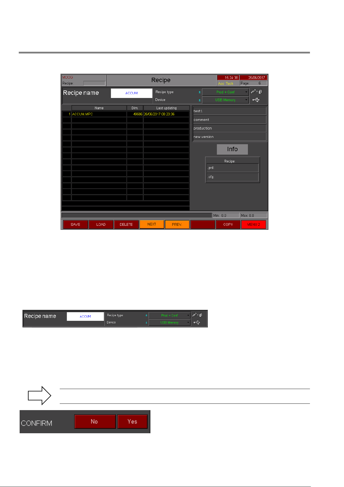
PARISON CONTROLLER
Recipe Type: With Technical level it is
possible to select the recipe type
choosing between Product,
Configuration or both.
4.17 Recipe.
moog
Figure 108
Recipe: Recipe page.
Access: From Main Menu 2 with key F4.
Use: In this page it’s possible to manage the recipes. It’s possible to save, load (only with machine in manual
mode) cancel or copy a recipe both on internal Ram Disk and on external USB by selecting the correct device.
It’s also possible to format the device.
Only a few recipes can be saved on Ram Disk (Max 6) while on USB it’s possible to save a lot of recipes.
4.17.1 Recipe Management.
With Responsible level it is possible to use only Product recipe. The .PRD file contains data relating to the mould.
(Work Head data, Extruder data, Accumulator data, Production data, Timer Switch data). The .CFG file contains
data relating to the configuration of the machine (Calibration Machine setup data, Number heads, Work Head setup
data, Extruder setup data, Accumulator setup data).
Recipe Name: Write the name of the recipe. The maximum number of characters is 8.
Device: Select the device where to save the recipe (Ram Disk or USB).
To safely execute the commands in this page (SAVE - LOAD - DELETE - FORMAT - COPY) it is
necessary to confirm the operation with the following popup.
Figure 109
100 MAN145-UM-D01A-EN Moog Italiana srl - Bergamo
 Loading...