

Page 1
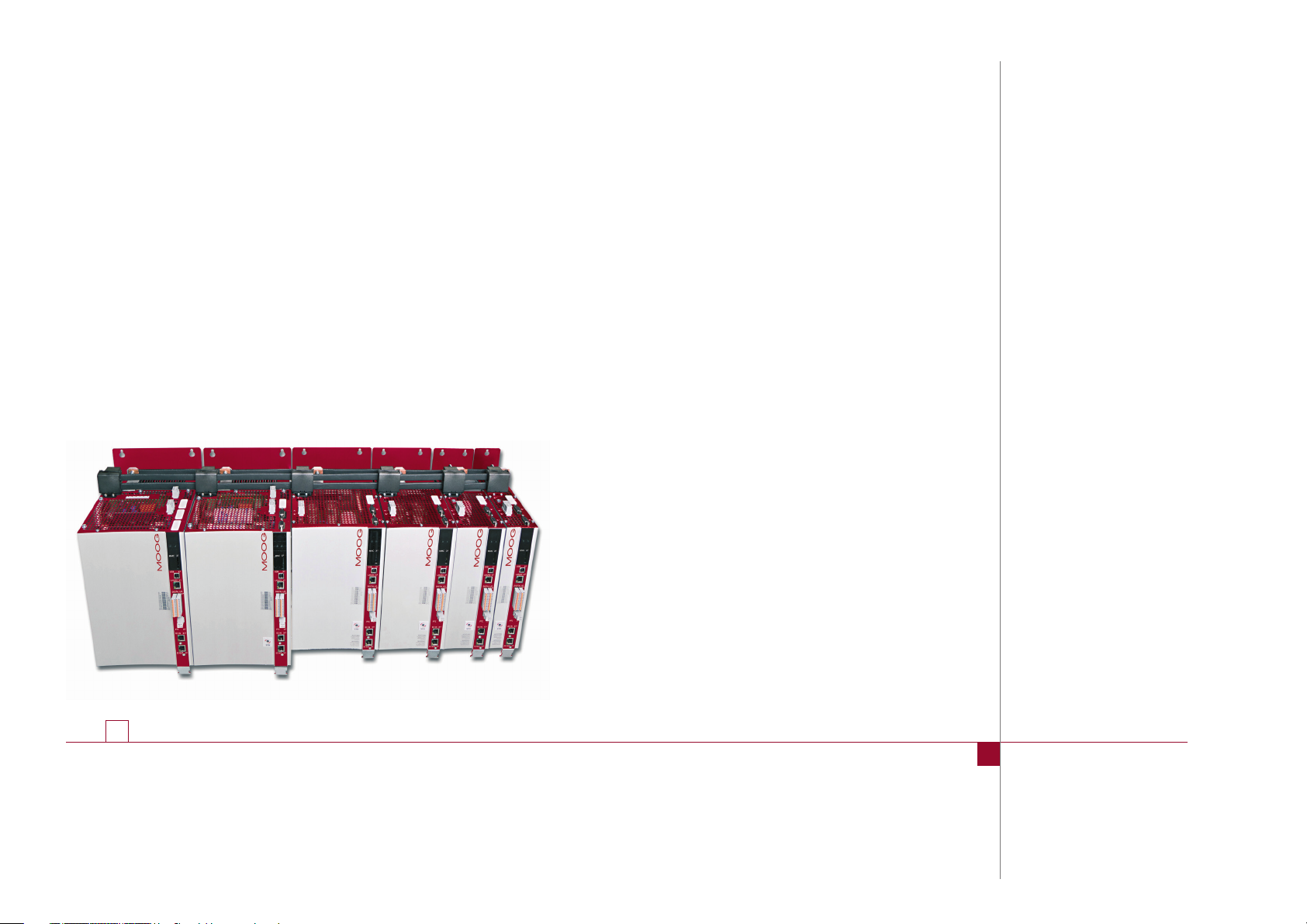
Programmable
Multi-Axis
Servo Drive
Power Supply Unit (PSU)
Sizes 5 and 6A
moog
Operation Manual
Power Supply Unit
with sinusoidal mains feedback
Page 2
moog
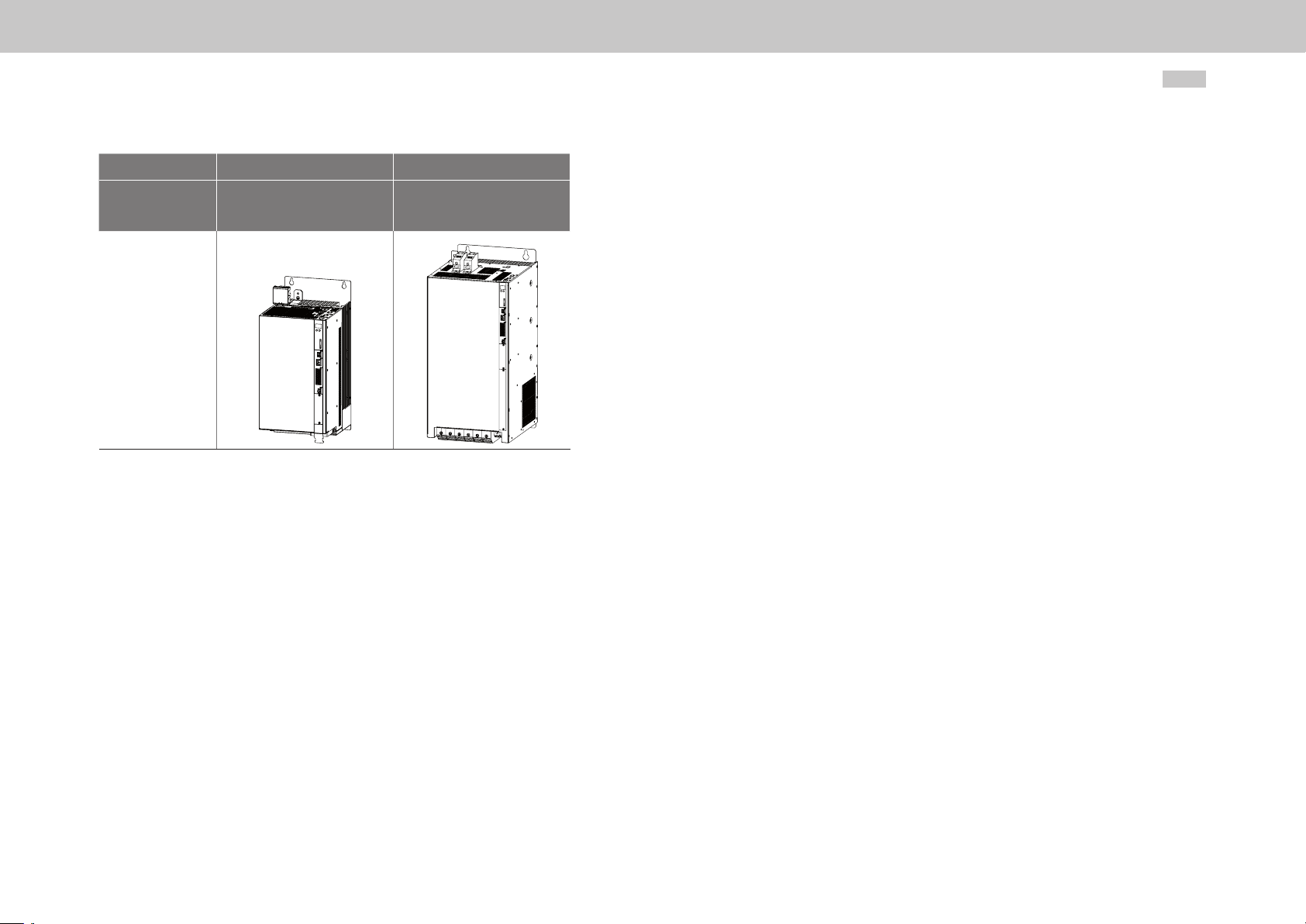
Size Size 5 Size 6A
Device
Picture
ID no.:CA97556-001 Date:03/2015
G396-026
G396-050
G396-075
G396-110
Programmable Multi-Axis Servo Drive Power Supply Unit Operation Manual
2
MSD Servo Drive high-performance drives
The modular design of Multi-Axis Servo Drive ensures optimal integration into the machine process. Whether in high-speed fieldbus communication with the central multi-axis
machine controller or with distributed programmable Motion Control intelligence in the
servo drive, the Multi-Axis Servo Drive is a master of both.
Programmable Multi-Axis
Servo Drive Power Supply Unit (PSU)
Operation Manual
ID no.:CA97556-001, Rev. 2.0
Date: 04/2015
Applicable as from firmware version: V220.13-01
The German version is the original of this Operation Manual.
We reserve the right to make technical changes.
The contents of our documentation have been compiled with greatest care and in
compliance with our present status of information.
Nevertheless we would like to point out that this document cannot always be updated
parallel to the technical further development of our products.
Information and specifications may be changed at any time. For information on the
latest version please refer to drives-support@moog.com.
Page 3
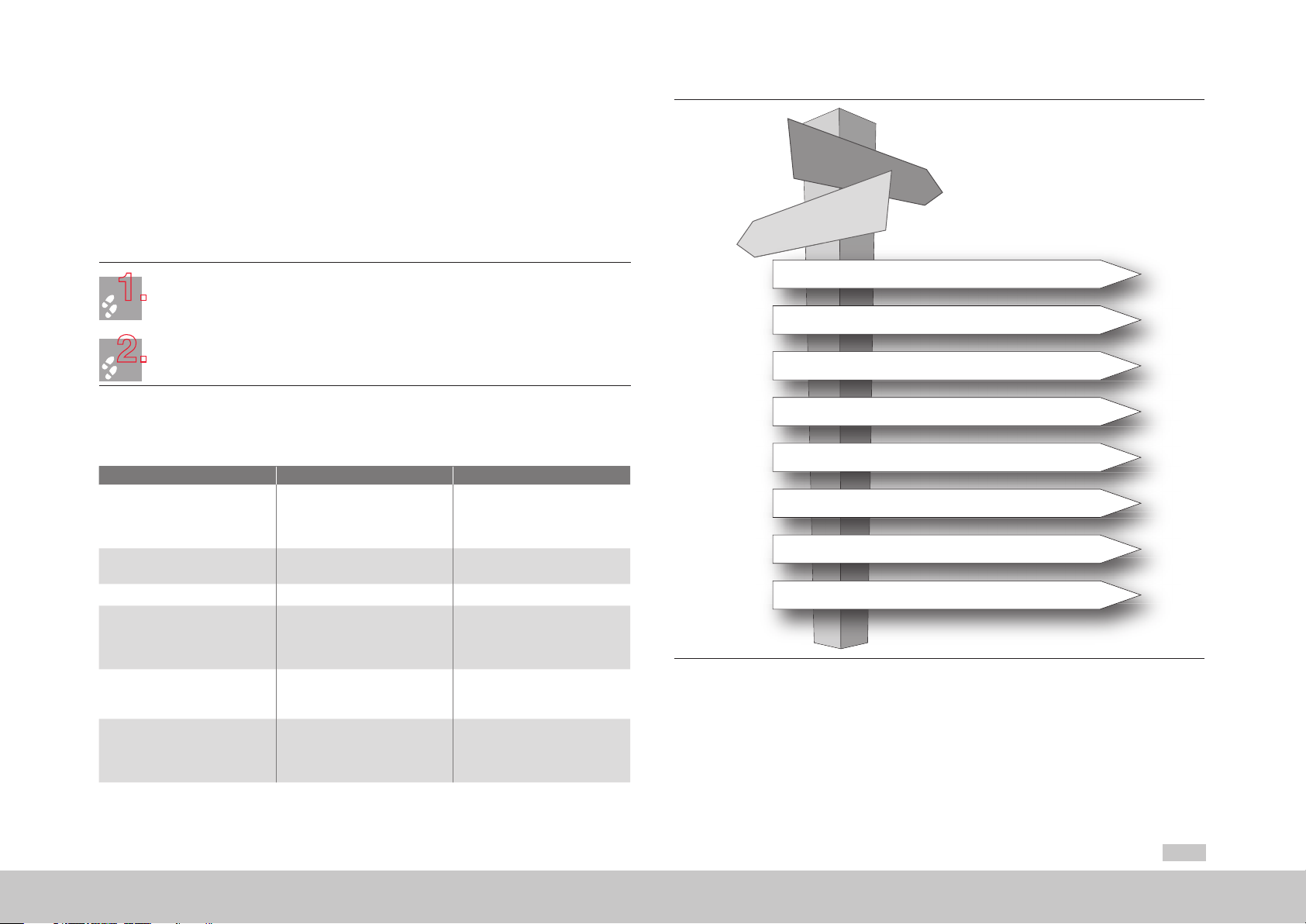
Guide through this document
1.
2.
Dear us er,
We are happy that you have made a decision in favour of a product from Moog. In order
to be able to start using your new device quickly and without problems, we ask you
kindly to read this Operation Manual thoroughly beforehand.
This Operation Manual will enable you to install and commission the Power Supply Unit very
quickly and easily.
Simply follow the step-by-step tables in the various chapters. And away you go!
Documentation system for the Programmable Multi-Axis Servo Drive
System (MSD)
Document Contents Description
Programmable Multi-Axis
Servo Drive Power Supply Unit
(PSU)
Operation Manuall
Programmable Multi-Axis
Servo Drive Operation Manual
MSD Servo Drive Device Help Description of base software Software
CANopen/EtherCAT User Manual
SERCOS User Manual
PROFIBUS / PROFINET
User Manual
Mechanical installation, Electrical
installation, Safety, Specification
Mechanical installation, Electrical
installation, Safety, Specification
Description and parameter setting of the MSD Servo Drive on
the CANopen/EtherCAT fieldbus
system
Description and parameter setting of the MSD Servo Drive on
the SERCOS II fieldbus system
Description and parameter
setting of the MSD Servo Drive
on the PROFIBUS / PROFINET
fieldbus system
Hardware and software
Hardware and software
Hardware and software of the
fieldbus option
Hardware and software of the
fieldbus option
Hardware and software of the
fieldbus option
1 Safety
2Overview
3Mechanical installation
4 Electrical installation
5 Commissioning
6 Diagnostics
A Appendix
Index
Figure 0.1 Guide through this document
moog
ID no.:CA97556-001 Date:03/2015
Guide through this document
Programmable Multi-Axis Servo Drive Power Supply Unit Operation Manual
3
Page 4
Guide through this document
moog
ID no.:CA97556-001 Date:03/2015
Order code
The order designation indicates the design variant of the Power Supply Unit supplied
to you. For details on the order code refer to the Programmable Multi-Axis Servo Drive
System (MSD) Ordering Catalog.
G396 -
Rated power
Option 1 (Communication)
For future use
Housing/cooling method
Option 4 (Function package)
Variants
- -
Programmable Multi-Axis Servo Drive Power Supply Unit Operation Manual
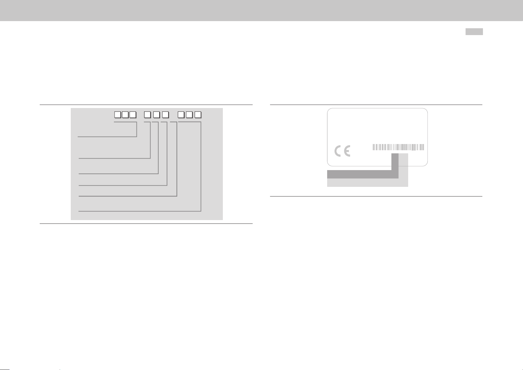
Production data
On rating plates of the Power Supply Unit you will find the serial number, from which
you can identify the date of manufacture based on the following key. You will find
details of the rating plate’s location on the Power Supply Unit starting on page13.
MOOG
D-71034 Böblingen
www .moog.com/industrial
Made in Germany
Year of production
Week of production
Figure 0.3 Hardware rating plate – Power Supply Unit
Model:: G396-040-000-002
S/N:D116605 Rev. A
In: 230 V AC 3ph, 50/60 Hz
0-230 V AC 3ph, 0-400 Hz
Out:
4,0 A
3,0 A
ID: YYCWxxxxx
4
Figure 0.2 Order code – Power Supply Unit
Supply package
The supply package includes:
y Power Supply Unit (PSU)
y Ready made-up DC link cables for size 5 and size 6A
y Product DVD
Page 5

Required mains connection set
1.
The mains connection set is required to ensure compliance with the intended use of the
Power Supply Unit. The supply package includes:
y Mains filter
y Input choke with membrane capacitor
y Step-up choke
y Shields and clamps
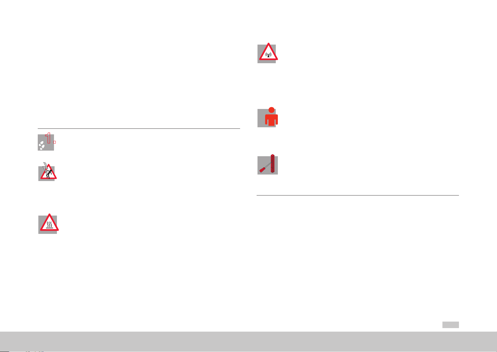
Pictograms
To provide clear guidance, this Operation Manual uses pictograms. Their meanings are
set out in the following table. The pictograms always have the same meanings, even
where they are placed without text, such as next to a connection diagram.
Warning symbols (see also section1.1, p.9)
ATTENTION!
Misoperation may result in damage to the drive or malfunctions.
!
DANGER FROM ELECTRICAL TENSION!
Improper behaviour may endanger human life.
Hints & Tips
NOTE:
Useful information or reference to other documents.
STEP:
Action in a sequence of multiple actions.
moog
ID no.:CA97556-001 Date:03/2015
Guide through this document
Programmable Multi-Axis Servo Drive Power Supply Unit Operation Manual
5
Page 6

Table of contents
moog
ID no.:CA97556-001 Date:03/2015
Table of contents
1 Safety ............................................................................................. 9
1.1 Measures for your safety ............................................................................................. 9
1.1.1 Read the Operation Manual first!.................................................................9
1.1.2 Warning symbols used ............................................................................... 10
1.2 Intended use ............................................................................................................. 10
1.3 Usage contrary to intended use ................................................................................. 10
1.4 Responsibility ............................................................................................................ 11
2 Mechanical installation.................................................................. 13
2.1 Notes for mechanical installation............................................................................... 13
2.2 Effective EMC installation..........................................................................................14
2.2.1 General notes ............................................................................................ 14
2.2.2 Cabinet design ........................................................................................... 14
2.3 Power Supply Unit installation Air-cooled housing ....................................................17
2.3.1 Dimensions, air-cooled housing ................................................................. 18
2.4 Power Supply Unit installation Liquid-cooled housing ............................................... 19
2.4.1 Dimensions, liquid-cooled housing ............................................................20
2.5 Cooling circuit connection.........................................................................................21
2.6 Step-up choke installation ......................................................................................... 22
2.6.1 Dimensions ................................................................................................22
2.7 Installation of input choke with membrane capacitor ................................................ 23
2.7.1 Dimensions ................................................................................................ 23
2.8 Mains filter installation .............................................................................................. 24
2.8.1 Dimensions ................................................................................................24
3 Electrical installation .....................................................................25
3.1 Before you start ........................................................................................................25
Programmable Multi-Axis Servo Drive Power Supply Unit Operation Manual
3.2 Effective EMC installation..........................................................................................25
3.2.1 Cable type .................................................................................................25
3.2.2 Cable laying ............................................................................................... 26
3.2.3 Earthing ..................................................................................................... 26
3.2.4 Shielding .................................................................................................... 27
3.3 Overview of connections ...........................................................................................28
3.3.1 Layout, size 5 (G396 -026 and G396-050) ..................................................28
3.3.2 Layout, size 6A (G396-075 and G396-110) ................................................28
3.3.3 Overview of connections, size 5 and size 6A .............................................. 29
3.3.4 Connection diagram, size 5........................................................................30
3.3.5 Connection diagram, size 6A .....................................................................32
3.4 Connection of PE conductors ....................................................................................33
3.4.1 PE conductor (X11)Power Supply Unit size 5 ..............................................33
3.4.2 PE conductor (X11)Power Supply Unit size 6A ...........................................34
3.4.3 PE conductor components .........................................................................35
3.5 Electrical isolation method ........................................................................................35
3.6 Connection of supply voltages ..................................................................................36
3.6.1 Control supply 24VDC (X9, X10) for size 5 and size 6A ............................36
3.6.2 Precharge and mains synchronisation (X21) for size 5 and size 6A .............37
3.6.3 Mains connection 400/480VAC (X12) for size 5 and Size6A ....................38
3.7 DC power supply connection .................................................................................... 40
3.7.1 DC power supply connection(X11) size 5 ....................................................41
3.7.2 DC power supply connection (X11) size 6A ................................................42
3.8 Control connections (X4)...........................................................................................44
3.8.1 Specification of control connections ..........................................................44
3.8.2 Standard terminal assignment .................................................................... 45
3.9 Functions of the digital inputs ...................................................................................46
3.10 Functions of the digital outputs ................................................................................46
6
Page 7

3.11 Specification of USB port (X2) ................................................................................... 47
3.12 Specification of Ethernet port (X3) ............................................................................ 47
3.13 Option 1 ...................................................................................................................47
3.14 Braking resistor (X12/RB) ........................................................................................... 47
3.14.1 Connection of the external braking resistor ............................................... 47
3.15 Overview of step-up choke connections....................................................................48
3.16 Overview of input choke connections .......................................................................49
3.17 Overview of mains filter connections .........................................................................50
4 Commissioning ............................................................................. 51
4.1 Notes for operation ................................................................................................... 51
4.2 Initial commissioning (actuation via terminals) ...........................................................51
4.2.1 System requirements ................................................................................. 52
4.2.2 Wiring of components ............................................................................... 52
4.2.3 Switching on control voltage (24 VDC) ......................................................53
4.2.4 Communication with the Moog Dr iveA Dmini strAtor 5 ................................. 53
4.2.5 Setting the mains voltage and frequency of the supply system ..................54
4.2.6 Automatic identification of DC link capacity and equivalent time
constant of current control ........................................................................ 55
4.2.7 Setting DC link capacity ............................................................................. 55
4.2.8 Setting DC link voltage .............................................................................. 56
4.2.9 Programming monitoring of the braking resistor ........................................56
4.2.10 Connecting the mains supply voltage ........................................................57
4.2.11 Activating closed-loop control ...................................................................57
4.3 Diagnostics ...............................................................................................................57
4.3.1 Faults and warnings in Moog Dri veAD m inist rAtor 5 .....................................57
4.4 Integrated operator control unit and MMC card .......................................................58
4.4.1 Functions of buttons T1 and T2 ................................................................. 59
4.4.2 Display .......................................................................................................59
4.4.3 Parameters menu (PA) ................................................................................ 60
4.4.4 Ethernet IP address menu (IP) ..................................................................... 61
4.4.5 Fieldbus address menu (Fb) ........................................................................ 62
4.4.6 Firmware update with MMC card .............................................................. 63
5 Diagnostics ...................................................................................64
5.1 Device states .............................................................................................................64
5.1.1 Er r or ..........................................................................................................64
5.2 Error list ....................................................................................................................65
5.3 Helpline/Service ........................................................................................................ 65
A Appendix ......................................................................................66
A.1 Technical data of Power Supply Unit .........................................................................66
A.2 Current consumption of control supply .....................................................................69
A.3 Ready made-up cables ..............................................................................................69
A.4 Hydrological data of liquid cooling ............................................................................70
A.5 Dynamic temperature monitoring .............................................................................70
A.6 Ambient conditions ...................................................................................................70
A.7 Technical data of step-up choke ................................................................................ 72
A.8 Technical data of input choke .................................................................................... 72
A.9 Technical data of mains filter ..................................................................................... 73
A.10 Technical data of mains fuse ..................................................................................... 73
A.11 Technical data of mains contactor ............................................................................. 73
A.12 Technical data of circuit-breaker ................................................................................ 73
A.13 Measures to attain UL approbation (UL508C) size 5 ................................................. 74
A.14 Measures to attain UL approbation (UL508C) size 6A .............................................. 74
B Overview ...................................................................................... 75
moog
ID no.:CA97556-001 Date:03/2015
Table of contents
Index ...................................................................................................78
Programmable Multi-Axis Servo Drive Power Supply Unit Operation Manual
7
Page 8

Table of contents
moog
ID no.:CA97556-001 Date:03/2015
Programmable Multi-Axis Servo Drive Power Supply Unit Operation Manual
8
Page 9
1 Safety
1.
1.1 Measures for your safety
The instructions set out below should be read through prior to initial commissioning
in order to prevent injury and/or damage to property. The safety instructions must be
followed at all times.
1.1.1 Read the Operation Manual first!
Read the Operation Manual and the reference documents first!
• Follow the safety instructions!
• Refer to the user information!
Electric drives are dangerous:
• Electrical voltages 230 V AC / 320 V DC to 480 V AC / 770 V DC
Dangerously high voltages ≥ 50 V (capacitor charge) may still be present 10 minutes after
the power is cut to the size 5 and size 6A. The discharge time depends on the number of
drives connected to the multi-axis system. So check that no voltage is connected!
• Rotating parts
• Hot surfaces
Risk of burning by hot components!
• The heat sink of the inverter, the choke, the transformer, the filters and the fuses become
very hot in operation.
− Make sure the components have cooled down to ambient temperature before carrying
out any work. Or wear protective clothing and gloves when working close to hot
components.
Risk of burning by hot coolant!
• The coolant gets hot during operation. Make sure the coolant has cooled down to ambient
temperature before carrying out any work.
Protection against magnetic and/or electromagnetic fields during installation and operation.
• Persons fitted with heart pacemakers, metallic implants and hearing aids etc. must not be
allowed access to the following areas:
− Areas where drive systems are installed, repaired and operated.
− Areas where motors are installed, repaired and operated. Motors with permanent
magnets pose a particular hazard.
NOTE:
If it is necessary to access such areas, suitability to do so must be determined beforehand by a
doctor
Your qualification:
• In order to prevent personal injury and damage to property, only personnel with electrical
engineering qualifications may work on the device.
• The said qualified personnel must be familiar with the contents of the Operation Manual
(see IEC364, DIN VDE0100).
• Knowledge of the national accident prevention regulations (e.g. BGV A3 in Germany)
U
U
V
During installation observe the following instructions:
V
N
N
L+
• Always comply with the connection conditions and technical specifications.
L+
RB
RB
L-
L-
L3
L3
L2
• Comply with the standards for electrical installations, suchas regarding wire cross-section,
L2
L1
L1
PE conductor and earth connections.
• Do not touch electronic components and contacts (electrostatic discharge may destroy
components).
Table 1.1 Safety precautions
moog
Safety
ID no.:CA97556-001 Date:03/2015
Programmable Multi-Axis Servo Drive Power Supply Unit Operation Manual
9
Page 10
Safety
moog
ID no.:CA97556-001 Date:03/2015
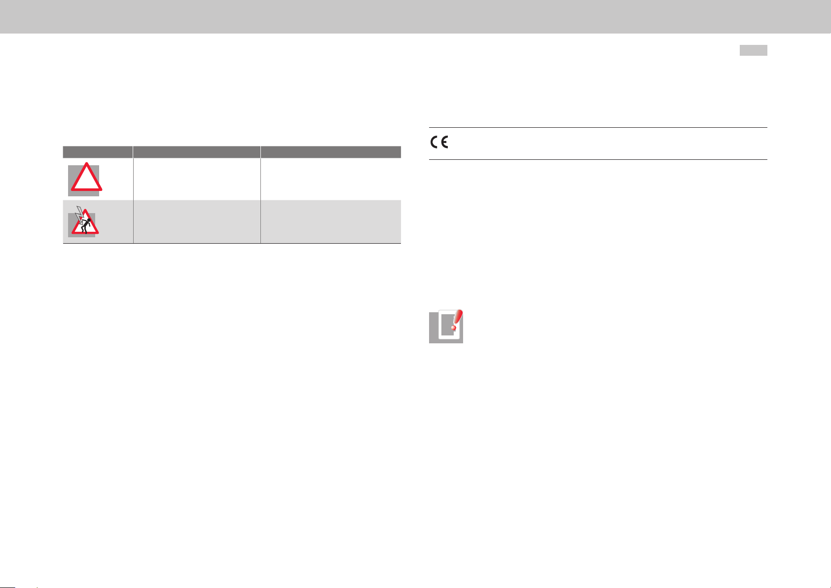
1.1.2 Warning symbols used
The safety instructions detail the following hazard classes. The hazard class defines the
risk posed by failing to comply with the safety notice.
Warning symbols General explanation Hazard class to ANSIZ535
ATTENTION!
!
Table 1.2 Explanations of warning symbols
Misoperation may result in damage to
the drive or malfunctions.
DANGER FROM ELECTRICAL
TENSION!
Improper behaviour may endanger
human life.
Serious injury or damage to property may
occur.
Death or serious injury will occur.
1.2 Intended use
The Power Supply Unit is intended for use in a Multi-Axis Servo Drive System. The multiaxis system comprises a Power Supply Unit with the mains connection set and a number
of Multi-Axis Servo Drives connected to it. In motorised mode, the Power Supply Unit
draws power from the supply system and makes it available to the connected Multi-Axis
Servo Drives via the DC link. In regenerative mode the power is stored in the DC link.
Temporarily surplus energy is fed back into the supply network by the Power Supply Unit
in sinusoidal form.
Programmable Multi-Axis Servo Drive Power Supply Unit Operation Manual
Commissioning (i.e. putting the device to its intended use) is only permitted in
compliance with the EMC Directive (2004 /108 /EC).
The Power Supply Unit conforms to the Low Voltage Directive 2006/95/EC.
The Power Supply Unit conforms to the requirements of the harmonised product
standard IEC/EN61800-5-1.
If the Power Supply Unit is used for special applications (e.g.in areas subject to explosion
hazard), the required standards and regulations (e.g. IEC/EN60079-0: "Explosive
atmospheres - Part0: Equipment - General requirements" and IEC/EN60079-1:
"Explosive atmospheres - Part1: Equipment protection by flameproof enclosures‚d’ “)
must always be observed.
Repairs may only be carried out by authorised repair workshops. Unauthorised opening
and incorrect intervention could lead to death, physical injury or material damage. The
warranty provided by Moog would thereby be rendered void.
NOTE:
Deployment of the Power Supply Unit in non-stationary equipment is classed
as non-standard ambient conditions, and is permissible only by special
agreement.
10
1.3 Usage contrary to intended use
The Power Supply Unit additionally performs the function of a reactive power
compensator as required. (For details please consult your project engineer.)
The Power Supply Unit is a component intended for installation in stationary electrical
systems or machines.
When installed in machines the commissioning of the servo drive (i.e. start-up of
intended operation) is prohibited, unless it has been ascertained that the machine fully
complies with the provisions of the Machinery Directive 2006/42/EC; compliance with
IEC/EN60204 is mandatory.
The Power Supply Unit must not be used:
y without the mains connection set (filters, chokes)
y outside a switch cabinet
y in a photovoltaic system
y with a directly connected DC motor
y in island mode
Page 11

1.4 Responsibility
Electronic devices are fundamentally not fail-safe. The company setting up and/or
operating the machine or system is itself responsible for ensuring that the drive is
rendered safe if the device fails.
IEC/EN60204-1: "Safety of machinery - Electrical equipment of machines - Part 1:
General requirements" in the category "Electrical equipment of machines" sets out
safety requirements for electrical controls. They are intended to protect personnel and
machinery, and to maintain the function capability of the machine or system concerned,
and must be observed.
The function of an emergency stop system does not necessarily have to cut the power
supply to the drive. To protect against danger, it may be more beneficial to maintain
individual drives in operation or to initiate specific safety sequences. Execution of
the emergency off measure is assessed by means of a risk analysis of the machine
or plant, including the electrical equipment to ENISO12100: "Safety of machinery General principles for design - Risk assessment and risk reduction", and is determined
with selection of the circuit category in accordance with ENISO13849-1: "Safety of
machinery - Safety-related parts of control systems - Part 1: General principles for
design" (formerly DINEN954-1).
moog
Safety
ID no.:CA97556-001 Date:03/2015
Programmable Multi-Axis Servo Drive Power Supply Unit Operation Manual
11
Page 12

moog
ID no.:CA97556-001 Date:03/2015
Programmable Multi-Axis Servo Drive Power Supply Unit Operation Manual
12
Page 13

2 Mechanical installation
2.1 Notes for mechanical installation
ATTENTION!
During installation, please avoid:
!
y drill chippings, screws or foreign bodies dropping into the device;
y penetration of damp into the device.
ATTENTION!
The device is solely intended for installation in a stationary cabinet. The
!
cabinet must as a minimum provide IP4x protection. The servo drives must not
be installed in areas where they would be permanently exposed to vibrations.
For more information refer to the Table A.13, p.71 appendix.
ATTENTION!
Risk of burning by hot components.
!
The device heats up in operation and at the heat sink may reach temperatures
of up to +100°C (+212 °F). The connected chokes get hot during operation,
possibly reaching temperatures of up to +145°C (+293°F).
Keep a safe distance away from adjacent component assemblies. Make sure
the components have cooled down to ambient temperature before carrying
out any work. Or wear protective clothing and gloves when working close to
hot components.
NOTE:
For installation of the Power Supply Unit within a Multi-Axis Servo Drive
System, be sure also to observe the Operation Manual for the Multi-Axis Servo
Drives.
The layout and installation of the Power Supply Unit and the Multi-Axis Servo Drives is
subject to the following basic rules:
y The backing plate must be well earthed.
y To attain the best result for effective EMC installation use a chromated or
galvanised backing plate. If backing plates are varnished, remove the coating
from the contact area. The size 5 and size 6A models have a rear panel made of
aluminised/galvanised sheet steel.
y Pollution severity 2 to IEC/EN60664-1. For more information on environmental
conditions refer to the Table A.11, p.70 appendix.
y Cooling air must be able to flow through the device without restriction.
y For installation in cabinets with convection (= heat loss is discharged to the
outside via the cabinet walls), always fit an internal air circulation fan.
y Devices with different housing variants (air-cooled and liquid-cooled) can be
installed next to each other in any combination.
y Devices with liquid-cooled housings have a spacer on the rear in place of the
heat sink. Consequently, it is possible to connect to devices with air-cooled
housings using the ready made-up DC link cables without additional measures
to compensate for differing unit depth.
y No minimum clearance between the devices is required. Exceptions to this rule
are the following air-cooled devices:
− Multi-Axis Servo Drive size 6A (Figure 2.5, p.17 and Table 2.1, p.18)
− Power Supply Unit size 6A (Figure 2.9, p.19 and Table 2.2, p.20)
y The maximum distance between the devices is dictated by the supplied ready
made-up cables, and is 2mm (0.08in) (for exceptions see above).
ATTENTION!
Use only the supplied DC link cable for the electrical connections between the
!
devices. If other cables are used, Moog can provide no guarantee of stable
and safe operation.
moog
ID no.:CA97556-001 Date:03/2015
Mechanical installation
Programmable Multi-Axis Servo Drive Power Supply Unit Operation Manual
13
Page 14

Mechanical installation
moog
y Servo Drives may only be installed on one side (to the left or right) of larger
sized devices. On the other side a device of equal or smaller size must be
installed.
y A vertical offset of 18.5mm (0.73in) must be allowed between the top fixing
screws for devices of size 1 to size 5 and devices of size 6A (see Figure 2.5 and
Figure 2.9).
If you need more details on installation please contact the Moog Helpline (see
section5.3, p.65).
ID no.:CA97556-001 Date:03/2015
2.2 Effective EMC installation
2.2.1 General notes
Power Supply Units are components intended for installation in industrial and
commercial plant and machinery. They must only be installed in switch cabinets
providing minimum IP4x protection.
Commissioning (i.e. starting intended operation) is only permitted when strictly
complying with EMC product standard IEC/EN61800-3.
NOTE:
The new EMC product standard for variable-speed electric drives is
IEC/EN 61800-3:2008. The transition period for the old IEC/EN61800-3:1996
ended on October1, 2007.
The installer/operator of a machine and/or item of plant must provide proof of
compliance with the protection targets stipulated in the EMC standard.
The multi-axis system is a special case with regard to EMC installation. The high
DClink voltage (up to 770 V DC) and its routing over long cables between the Power
Supply Unit and Multi-Axis Servo Drives demands great care when implementing EMC
installation.
Programmable Multi-Axis Servo Drive Power Supply Unit Operation Manual
14
2.2.2 Cabinet design
The placement of components in the switch cabinet is a key factor in operating plant
and machinery without disturbance. Your planning should take account of the following
points:
y Assess the assemblies used in terms of their electromagnetic compatibility.
y Split the cabinet into zones of different power and interference levels.
y Keep units susceptible to interference at a minimum clearance of 200mm
(7.87in) from the following components:
− Servo drive
− Input and output chokes, transformers
− Mains, motor, DC power supply and braking resistor cables (even if shielded)
− Relays and contactors (even if interference-suppressed)
y When installing close, use isolating plates mounted directly and conductively on
the backing plate as shielding.
y When using a motor contactor or a reactance coil, the respective component
should be directly mounted to the servo drive.
y Do not use fluorescent lamps in cabinets, as they emit high-frequency
interference.
y Provide contactors, relays, solenoid valves, switched inductors and capacitors
with suppressors.
y The mains filter must be sealed tight as far as possible, and be mounted on
the backing plate across a wide area at the feed-in point. The backing plate
must have a low-resistance connection to the central earthing point. No
unfiltered cables may be routed on the mains input side of the filter, to prevent
interference.
Timely planning and diligent implementation of the EMC installation measures detailed
here will help avoid complex and costly retooling of plant.
Page 15
< 200 mm
< 20
12 9
1) Power cable
2) Main s witch
3) Fuses
4) Mains filt er Unfiltered cables must be routed at a distance of least 20 0 mm (7.87in) from the mains input side of the fi lter,
to prevent interfer ence.
5) Circuit-breaker
11
PWR
LOCK
CF
14
6) Mains contactor
7) Input choke with connected capacitor
8) Step-up choke
9) Powe r Supply Unit
Power
COM
Data
Status
10
10
10
10
Reset
RJ-45/Line
RS 232
10) Multi-Axis Servo Drive
11) DC power supply via DC link cable
12) Braking resistor
13) Motor cables
14) Control
3
0
5
1
OFF
ON
0
2
Figure 2.1 Example: Cabinet layout
NOTE:
6
8
4
13
Arrange the control section separately from the power section, so as to avoid
electromagnetic interference mechanisms.
Control and signal cables and shields have been omitted for the sake of clarity.
1
7
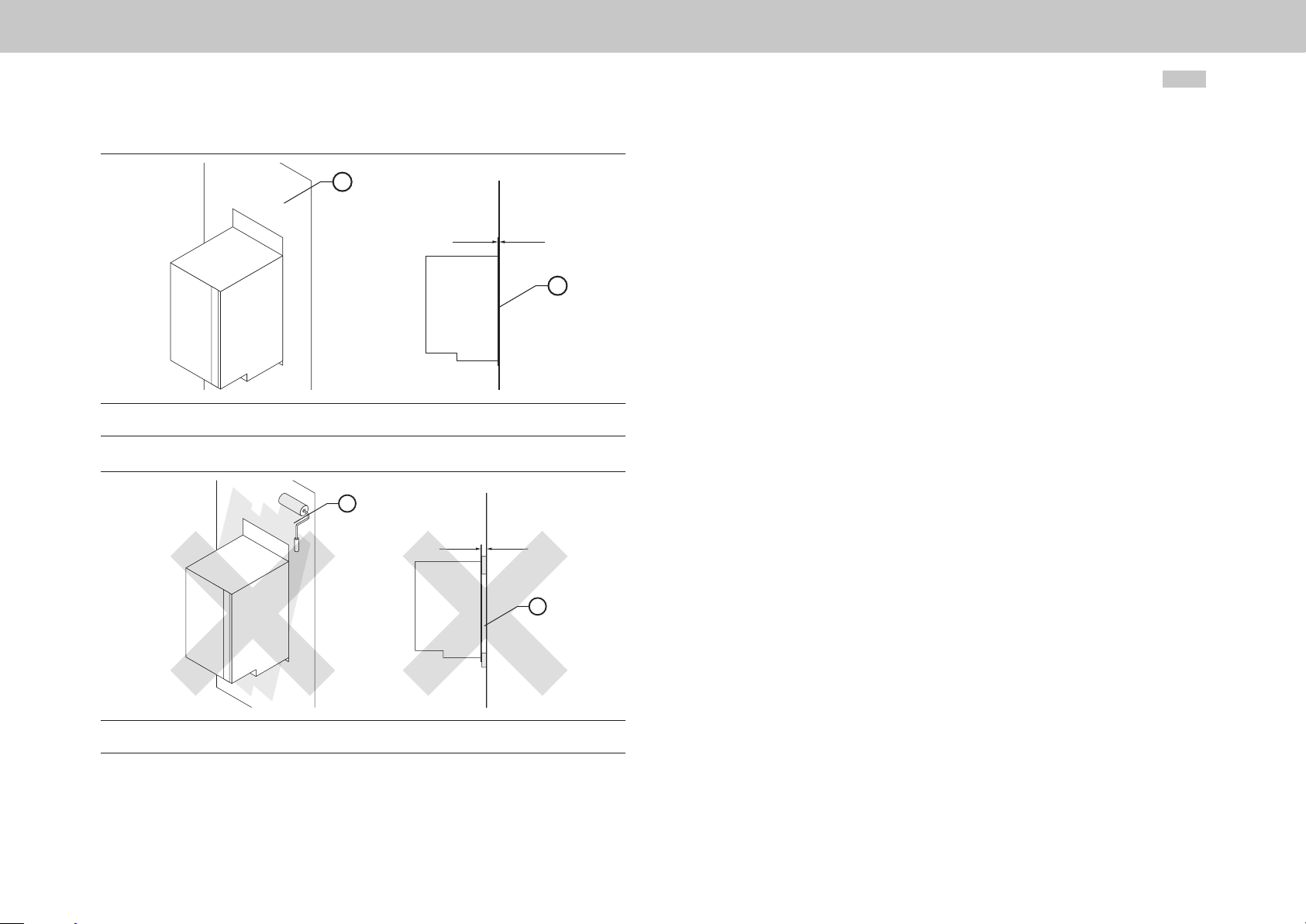
y Use metallically bright backing plates.
y The rear panel of the servo drive must have good contact with the switch
cabinet earth. The contact area must be metallically bright, in order to make a
good earth connection to the cabinet earth. There must be no air gap between
the rear panel of the servo drive and the switch cabinet wall.
y The choke bases must have good contact with the cabinet earth. The contact
area must be metallically bright, in order to make a good earth connection to
the cabinet earth.
moog
ID no.:CA97556-001 Date:03/2015
Mechanical installation
Programmable Multi-Axis Servo Drive Power Supply Unit Operation Manual
15
Page 16
Mechanical installation
moog
1) Backing plate metallically bright
2) Wide- area contact
Figure 2.2 Servo drive installation CORRECT
ID no.:CA97556-001 Date:03/2015
Programmable Multi-Axis Servo Drive Power Supply Unit Operation Manual
1
= 0 mm
2
1
16
1) Va rnis h
2) Air gap
Figure 2.3 Servo drive installation INCORRECT
> 0 mm
2
Page 17
18.5 mm (0.73 in)
18.5 mm (0.73 in)
Multi-Axis Servo Drive size 1
Multi-Axis Servo Drive size 2
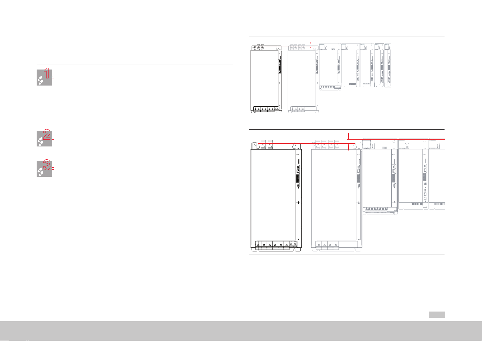
2.3 Power Supply Unit installation
1.
2.
3.
Air-cooled housing
Arrange the devices starting from the Power Supply Unit to the right or left sorted in descending
order of power output, in order to exclude thermal influences. Before installing the devices and
components in the cabinet refer to the instructions relating to EMC installation.
Align Power Supply Unit size 5 and all Multi-Axis Servo Drives in a line along the top edge of
the unit (see dotted line in Figure 2.4). This is necessary in order to execute the DC power supply
using the ready made-up cables.
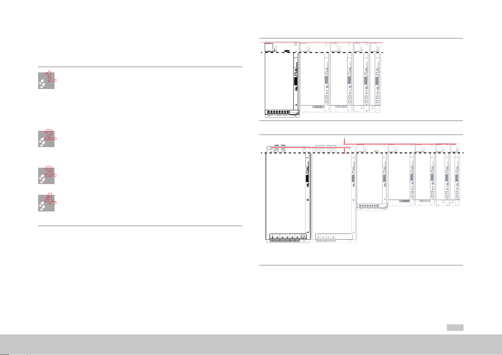
Align all Multi-Axis Servo Drives in a line along the top edge of the unit. Align Power Supply Unit
size 6A offset 18.5mm (0.73in) down (see Figure 2.5). This is necessary in order to execute
the DC power supply using the ready made-up cables. Be sure to adhere to the mounting
clearances set out in Ta b le 2.1.
Mark out the position of the tapped holes on the backing plate.
Cut a tap for each fixing screw in the backing plate.
Pay attention to the installation clearances. Also take into account the bend radius of the
connecting cables. Dimensional drawings/hole spacing see Figure 2.6 and Tab l e 2.1..
Mount the Power Supply Unit vertically and abutting on the backing plate.
The contact area must be metallically bright. For the DC power supply use the supplied ready
made-up cables. The next stage is installation of the mains connection set.
Power Supply Unit
size 6A
Figure 2.4 Butt-mounting, axis array, air-cooled, with Power Supply Unit size 5
Power Supply Unit
size 6A
air-cooled
Multi-Axis Servo Drive
size 6A
Multi-Axis Servo Drive size 5
Multi-Axis Servo Drive
size 6A
air-cooled
Multi-Axis Servo Drive size 2
Multi-Axis Servo Drive size 4
Multi-Axis Servo Drive size 3
Multi-Axis Servo Drive size 1
Multi-Axis Servo Drive size 5
Multi-Axis Servo Drive size 4
Multi-Axis Servo Drive size 3
moog
ID no.:CA97556-001 Date:03/2015
Mechanical installation
Figure 2.5 Butt-mounting, axis array, air-cooled, with Power Supply Unit size 6A
Programmable Multi-Axis Servo Drive Power Supply Unit Operation Manual
17
Page 18

Mechanical installation
moog
ID no.:CA97556-001 Date:03/2015
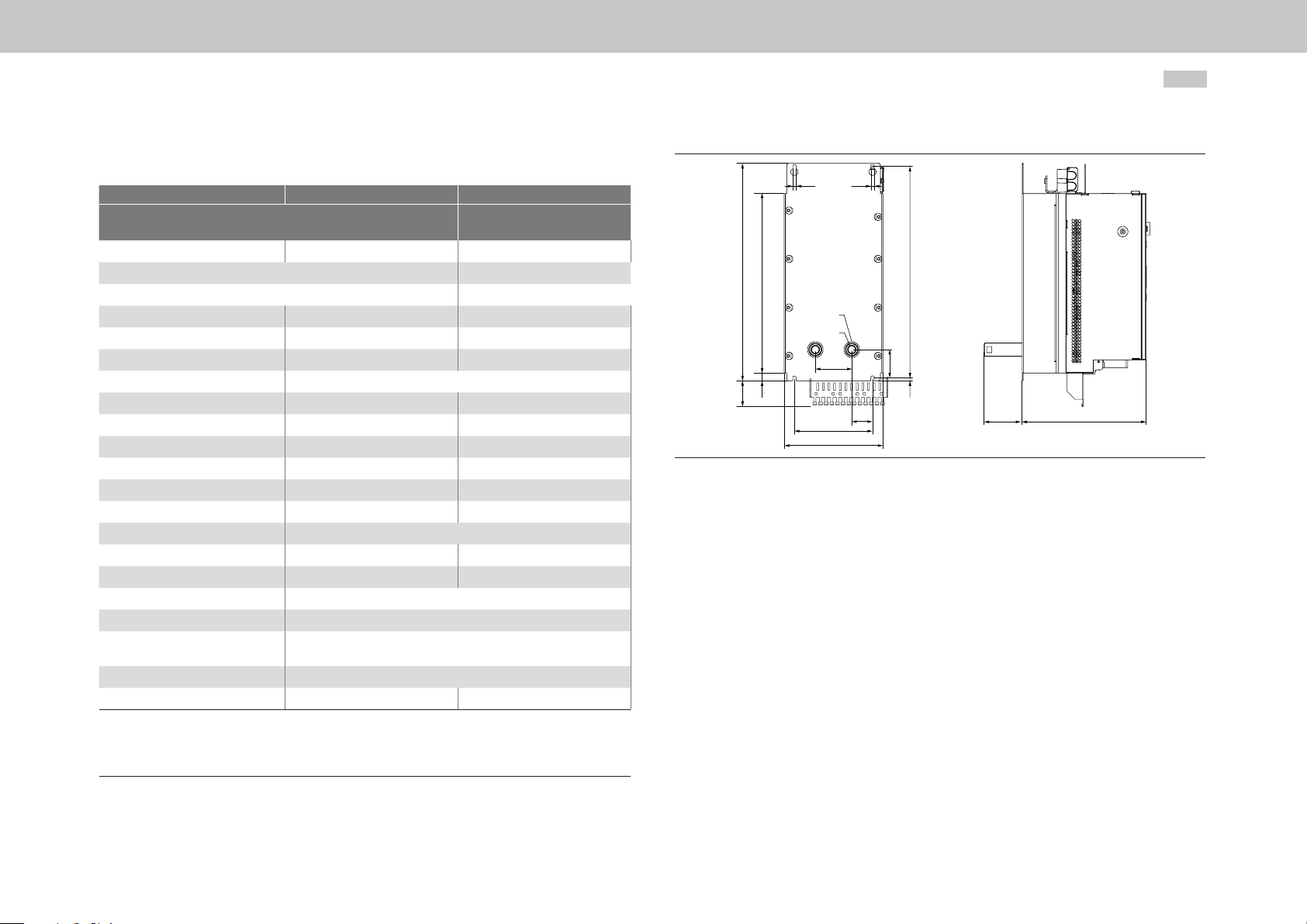
2.3.1 Dimensions, air-cooled housing
Size Size 5 Size 6A
Device
Weight
B (width)
H (height)
T (depth)
A
C
C1
H1
H2
H3
D
Fixing screws
E
F
G
All Dimensions in mm (in),
1) Without terminals, connectors
2) Mounting distance size 6A to other size 6A
3) Also take into account the bend r adius of the connecting cables
Table 2.1 Dimensions, air-cooled housing
1)
1)
3)
3)
G396-026-xxx-xxx
G396-050-xxx-xxx
13 kg (28.7 lb) 32 kg (70.6 lb)
19 0 (7.4 8) 28 0 (11. 02)
345 (13.58) 540 (21.26)
240 (9.45) 322 (12.68)
150 (5.91) 20 0 (7. 87)
407 (16.02) 581 (22.87)
6 (0.24) 10 (0.39)
419 (16 .5 0) 600 (23.62)
15 (0.59) 20 (0.79)
64 (2.52) 166 (6.54)
Ø 6 (0.24) Ø 10 (0.39)
4 x M5 4 x M8
Direct butt-mounted, maximum
2(0.08)
≥30 0 (11. 81) ≥500 (19.69)
≥18 0 (7.0 9)
G396-075-xxx-xxx
G396-110-xxx-xxx
Direct butt-mounted, maximum
2(0.08) / 40
Programmable Multi-Axis Servo Drive Power Supply Unit Operation Manual
D D
H1
H
H2
H3
A
B
Figure 2.6 Dimensional drawing, air-cooled housing, example for size 5
2)
E
C
C1
T
F
G
18
NOTE:
Arrange devices with different drive power in descending order of power
output (e.g. viewed from the left size 4-size 3-size 2-size 1). This minimises the
mutual thermal influence. The Power Supply Unit must always be arranged on
the side of the most powerful servo drive. When butt-mounting other devices
with the multi-axis system, you must make sure that the devices do not affect
one another thermally.
F
Figure 2.7 Mounting distance, air-cooled housing, example for size 5
Page 19
18.5 mm (0.73 in)
2.4 Power Supply Unit installation
1.
2.
3.
4.
Liquid-cooled housing
Arrange the devices starting from the Power Supply Unit to the right or left sorted in descending
order of power output, in order to exclude thermal influences. Before installing the devices and
components in the cabinet refer to the instructions relating to EMC installation.
Align Power Supply Unit size 5 and all Multi-Axis Servo Drives in a line along the top edge of
the unit (see dotted line in Figure 2.8). This is necessary in order to execute the DC power supply
using the ready made-up cables.
Align all Multi-Axis Servo Drives in a line along the top edge of the unit. Align Power Supply Unit
size 6A offset 18.5mm (0.73in) down (see Figure 2.9). This is necessary in order to execute
the DC power supply using the ready made-up cables.
Mark out the positions of the tapped holes and the pipe socket on the backing plate.
Drill holes and cut a thread for each fixing screw in the backing plate.
Pay attention to the installation clearances. Also take into account the bend radius of the
connecting cables. Dimensional drawings/hole spacing see Figure 2.8 to Figure 2.10 and
Table 2.2.
Power Supply
Unit size 5
Multi-Axis Servo Drive size 2
Multi-Axis Servo Drive size 4
Figure 2.8 Butt-mounting, axis array, liquid-cooled, Power Supply Unit size 5
Multi-Axis Servo Drive size 3
Multi-Axis Servo Drive size 1
Mount the Power Supply Unit vertically and abutting on the backing plate.
When fitting the hose connections (not supplied) in the pipe sockets, brace with a 22mm
moog
The contact area must be metallically bright. For the DC power supply use the supplied ready
made-up cables.
(0.87in) open-ended wrench in order to prevent damage to the device by torsion.
Ensure a perfect liquid-tight connection (e.g. using a Teflon sealing strip).
For more information on liquid cooling refer to sectionA.4, p.70.
The next stage is installation of the mains connection set.
ID no.:CA97556-001 Date:03/2015
Power Supply Unit
size 6A
liquid-cooled
Figure 2.9 Butt-mounting, axis array, liquid-cooled, Power Supply Unit size 6A
Programmable Multi-Axis Servo Drive Power Supply Unit Operation Manual
Multi-Axis Servo Drive
size 6A
liquid-cooled
Multi-Axis Servo Drive size 5
Multi-Axis Servo Drive size 4
Multi-Axis Servo Drive size 3
Multi-Axis Servo Drive size 1
Multi-Axis Servo Drive size 2
19
Mechanical installation
Page 20
Mechanical installation
moog
ID no.:CA97556-001 Date:03/2015
2.4 .1 Dimensions, liquid-cooled housing
Size Size 5 Size 6A
Device
Weight
B (width)
H (height)
T (depth)
A
A1
1)
1)
G396-026-xxx-xxx
G396-050-xxx-xxx
13 kg (28.7 lb) 32 kg (70.6 lb)
19 0 (7.4 8) 280 (11. 02)
345 (13.58) 540 (21.26)
239 (9.41) 28 5 (11.22 )
150 (5.91) 20 0 (7. 87)
40 (1.57) 65 (2.56)
A2
C
407 (16.02) 581 (22.87)
C1
H1
H2
H3
H4
419 (16 .5 0) 600 (23.62)
15 (0.59) 20 (0.79)
54 (2.13) 57 (2.24)
64 (2.52) 166 (6.5 4)
D1
D
Ø 7 (0.28) Ø 10 (0.39)
Fixing screws
S inside thread
D1 Hole for pipe socket
2)
E
2) 3)
F
2) 3)
G
All dimensions in mm (in)
1) Without terminals/connectors
2) See F igu re 2 .11,
3) Also take into account the bend r adius of the connecting cables
≥30 0 (11. 81) ≥ 500 (19.69)
Table 2.2 Dimensions, liquid-cooled housing
70 (2.76)
6 (0.24) 10 (0.39)
74 (2.91)
4 x M6 4 x M8
3/8 inch
Ø 48 (1.89)
Direct butt-mounted, maximum 2 (0.08)
≥18 0 (7.0 9)
G396-075-xxx-xxx
G396-110-xxx-xxx
Programmable Multi-Axis Servo Drive Power Supply Unit Operation Manual
D
H1H4H
D
C
D1
S
A2
H2
A
H3
C1
A1
T1
B
Figure 2.10 Dimensional drawing, liquid-cooled housing, example for size 5
20
T
Page 21

E
F
G
2.5 Cooling circuit connection
NOTE:
Connect the liquid cooling feed to the connection marked. The cooling circuit
must be vented prior to commissioning. For more information on liquid
cooling refer to sectionA.4, p.70.
The device holds approximately 0.5litres of cooling fluid. When the connections have
been cut, there may still be residual fluid in the device which may spill out if it is tipped.
We recommend using a non-drip fluid coupling (not supplied) to prevent leakage of
cooling fluid and enable connecting and disconnecting the device while filled with fluid.
The connection set cooling circuit can be ordered separately.
F
Figure 2.11 Mounting distance, liquid-cooled housing, example for size 5
NOTE:
Arrange devices with different drive power in descending order of power
output (e.g. viewed from the left size 4-size 3-size 2-size 1). This minimises the
mutual thermal influence. The Power Supply Unit must always be arranged on
the side of the most powerful servo drive.
When butt-mounting other devices with the multi-axis system, you must make
sure that the devices do not affect one another thermally.
1
2
1) Liquid connec tion with 3/8inch inside thread
2) 90°angle conne ctor with 3/8inch insid e and outside thread
3) Non-drip fluid coupling
4) Non-drip quick-coupler with hose connection
5) PUR (polyurethane) hose with clamp
Items 2 to 5 are not include d in the supply package.
Figure 2.12 Cooling circuit connection
flow return
2
3
4
5
returnflow
moog
ID no.:CA97556-001 Date:03/2015
Mechanical installation
Programmable Multi-Axis Servo Drive Power Supply Unit Operation Manual
21
Page 22
Mechanical installation
1.
2.
moog
ID no.:CA97556-001 Date:03/2015
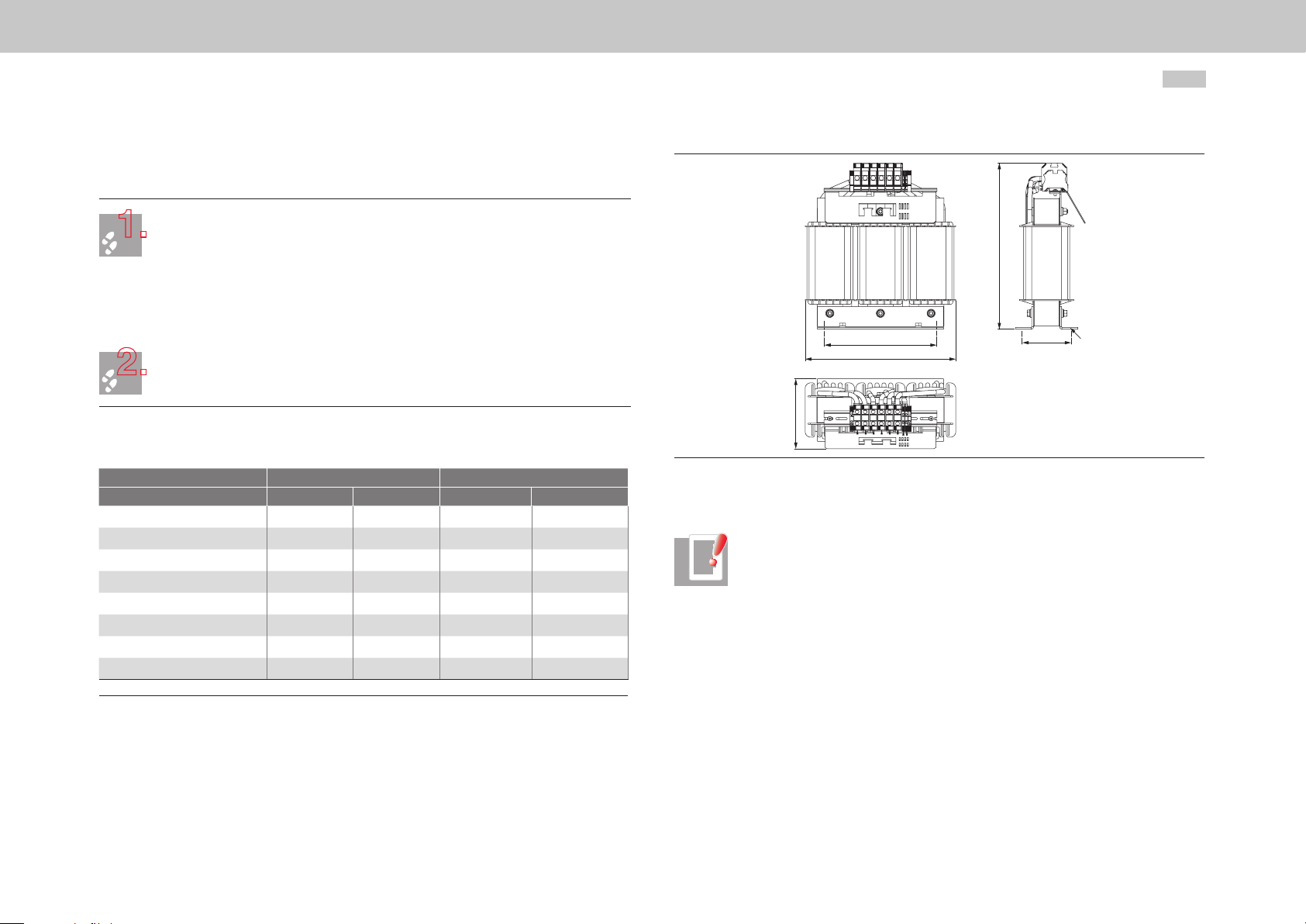
2.6 Step-up choke installation
Arrange the components and cables at a distance of >100 mm (3.94 in) from the step-up choke,
Mount the step-up choke on the mounting rail.
2.6.1 Dimensions
For size Size 5 Size 6A
For model G396-026 G396-050 G396-075 G396-110
B (width)
H (height)
T (depth)
A
A1
D1
Fixing screws
Weight
All dimensions in mm (in) and excluding terminals/connectors
Table 2.3 Step-up choke dimensions
so as to minimise influencing of the adjacent components by magnetic leakage flux and ensure
adequate air circulation for cooling. Position the step-up choke as close as possible to the Power
Supply Unit.
Mark out the position of the tapped holes on the mounting rail.
Cut a tap for each fixing screw in the backing plate.
Take into account the bend radius of the connecting cables.
Dimensional drawings/hole spacing see Figure 2.13 and Tabl e 2.3.
The tapping area will provide you with good, full-area contact. The contact area must be
metallically bright, in order to make a good earth connection to the cabinet earth.
239 (9.41) 29 9 (11.77) 335 (13.19) 380 (14.96)
273 (10.79) 30 0 (11.81) 34 4 (13.54) 3 99 (15.71)
124 (4. 88) 135 (5. 31) 158 (6.22) 200 ( 7. 87)
185 (7.28) 210 (8.27) 248 (9.76) 280 (11. 02)
75 (2.95) 95 (3.74) 122 (4.80) 127 ( 5.0)
10 x Ø 18 (0.71) 12 x Ø 20 (0.79) 12 x Ø 20 (0.79) 12 x Ø 20 (0.79)
4 x M8 4xM10 4xM10 4xM10
16 kg (35.27 lb) 27 kg (59.52 lb) 37.5 kg (82.67 lb) 56 kg (123.46 lb)
Programmable Multi-Axis Servo Drive Power Supply Unit Operation Manual
H
D1
A
B
T
Figure 2.13 Dimensional drawing, step-up choke, example for size 5 and size 6A
NOTE:
The step-up choke is a primary heat source, and should be treated as a
hotspot component. This component is cooled by natural air convection
(gravity circulation). In order to make effective use of this physical effect, this
component should be installed in the lower plinth area of the switch cabinet
on stable mounting rails (permitting unhindered air flow from below). When
selecting the position, air inlet at the filter mat or – better still – at the input
fan zone is advisable.
A1
22
Page 23
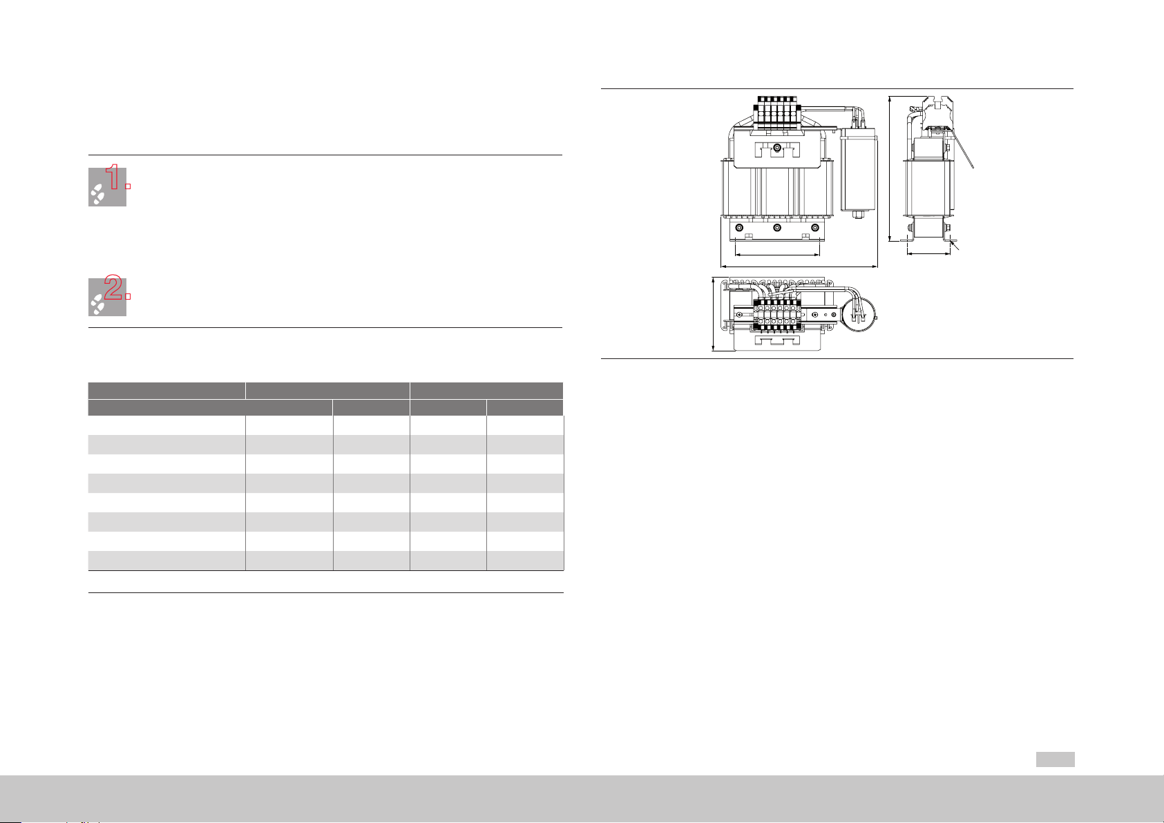
2.7 Installation of input choke with membrane
1.
2.
capacitor
Arrange the components so as to ensure sufficient air circulation for cooling. As the membrane
Mount the input choke on the mounting rail.
capacitor has a viscose filling, the input choke must be installed upright with the membrane
capacitor.
Mark out the position of the tapped holes on the mounting rail.
Cut a tap for each fixing screw in the backing plate.
Take into account the bend radius of the connecting cables.
Dimensional drawings/hole spacing see Figure 2.14 and Tabl e 2 .4 .
The tapping area will provide you with good, full-area contact. The contact area must be
metallically bright, in order to make a good earth connection to the cabinet earth.
2.7.1 Dimensions
For size Size 5 Size 6A
For model G396-026 G396-050 G396-075 G39 6 -110
B (width)
H (height)
T (depth)
A
A1
D1
Fixing screws
Weight
All dimensions in mm (in) and excluding terminals/connectors
28 9 (11. 3 8) 289 (11.38) 342 (13.47 ) 348 (13.70)
252 (9.92) 268 (10.55) 292 (11.50) 321 (12.6 4)
119 (4 . 8 6 ) 136 (5.35) 175 (6.89 ) 175 (6. 89)
156 ( 6.14) 156 (6.14) 176 (6.93) 176 (6.93)
63 (2.48) 80 (3 .15) 95 (3.74) 95 (3.74)
7 x Ø 13 (0.51) 7 x Ø 13 (0.51) 9 x Ø 13 (0.51) 9 x Ø 13 (0.51)
4 x M6 4 x M6 4 x M8 4 x M8
10.5 kg (23.15 lb) 14 kg (30.86 lb) 20 kg (44.09 lb) 22 kg (48.50 lb)
H
A
B
T
Figure 2.14 Dimensional drawing, input choke, example for size 5
A1
D1
Table 2.4 Input choke dimensions
moog
ID no.:CA97556-001 Date:03/2015
Mechanical installation
Programmable Multi-Axis Servo Drive Power Supply Unit Operation Manual
23
Page 24
Mechanical installation
1.
2.
moog
ID no.:CA97556-001 Date:03/2015
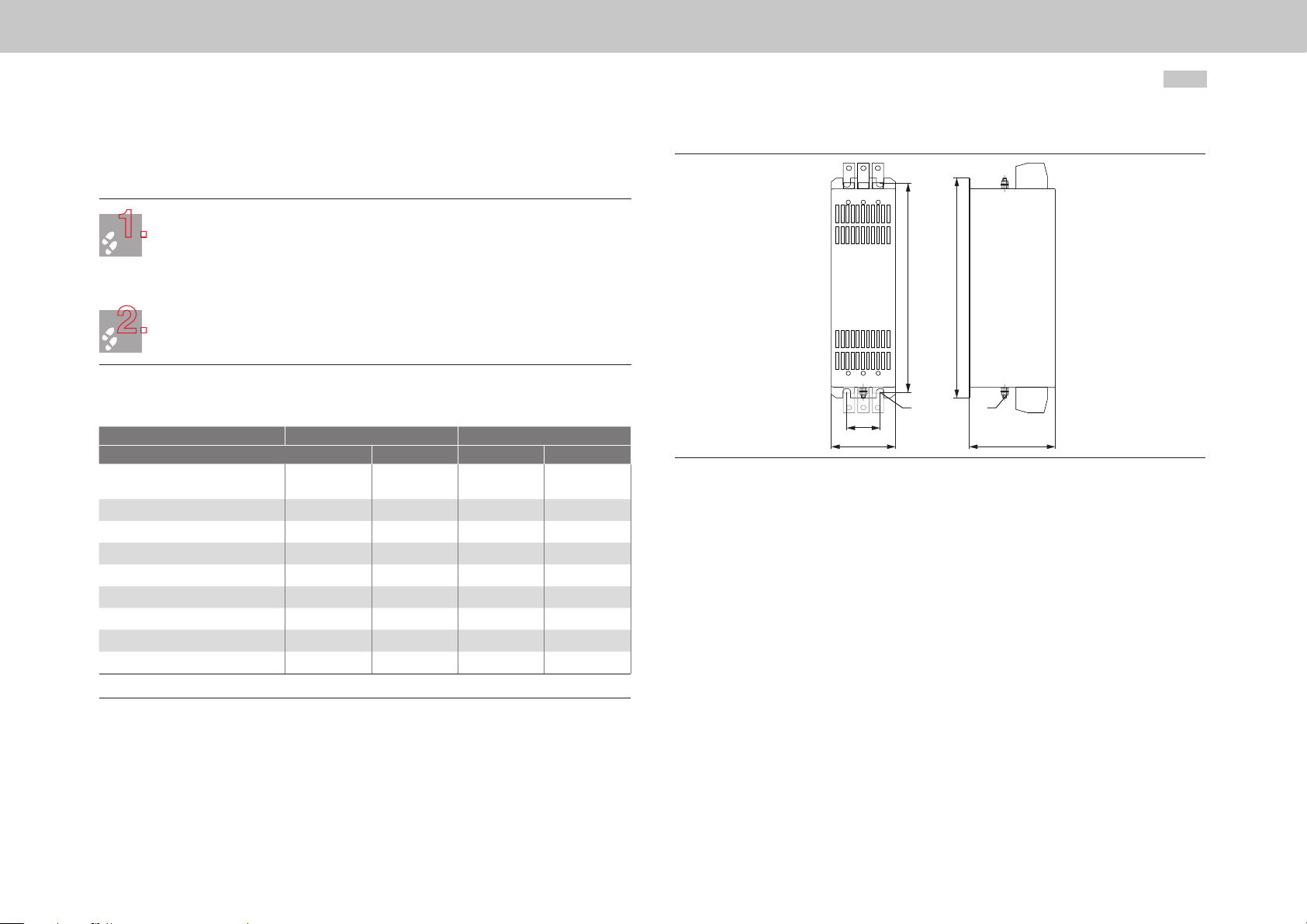
2.8 Mains filter installation
Arrange the components so as to ensure sufficient air circulation and cooling.
Mount the mains filter on the backing plate.
2.8 .1 Dimensions
For size Size 5 Size 6A
For model G396-026 G396-050 G396-075 G 396-110
Type
B (width)
H (height)
T (depth)
A
C
G Ø
Mounting screws
Weight
All dimensions in mm (in) and excluding terminals/connectors
Mark out the position of the tapped holes on the backing plate.
Cut a tap for each fixing screw in the backing plate.
Take into account the bend radius of the connecting cables.
Dimensional drawings/hole spacing see Figure 2.15 and Table 2.5.
The tapping area will provide you with good, full-area contact. The contact area must be
metallically bright.
FFU 3 x 56 K FFU 3 x 80 K FFU 3 x 130 K FFU 3 x 180 K
85 (3.35) 8 0 (3.15) 90 (3.54) 130 (5.12)
250 (9.84) 270 (10.63) 270 (10.63) 380 (14.96)
90 (3.54) 135 (5.31) 150 (5.91) 180 (7. 0 9)
60 (2.36) 60 (2.36) 65 (2.56) 102 (4.02)
235 (9.25) 225 (8.86) 255 (10.04) 365 (14.37)
5.4 (0.21) 6.5 (0.26) 6.5 (0.26) 6.5 (0.26)
M5 M6 M6 M6
1.9 kg (4.19 lb) 2.6 kg (5.73 lb) 4.2 kg (9.26 lb) 6.0 kg (13.23 lb)
Programmable Multi-Axis Servo Drive Power Supply Unit Operation Manual
H
C
A
B
Figure 2.15 Dimensional drawing, mains filter, example for size 5 and size 6A
Ø G PE
T
24
Table 2.5 Mains filter dimensions
Page 25
3 Electrical installation
3.1 Before you start
Please be sure to observe the following notices and warnings before and during
electrical installation.
DANGER FROM ELECTRICAL TENSION!
Danger to life! Never wire or disconnect electrical connections while they are
!
live. Always disconnect the power before working on the device. Dangerously
high voltages ≥50V (capacitor charge) may still be present 10minutes after
the power is cut to the size 5 and size 6A. The discharge time depends on
the number of drives connected to the multi-axis system. So check that the
power has been cut! Hazardous voltage may be applied to the device, even if
the device does not show any visual signs or emit any audible signals. On the
size 5 and size 6A for example: with mains voltage applied to terminal X12 or
X21 and missing control voltage +24V on X9, X10. So check that no voltage is
connected!
ATTENTION!
Installation must only be carried out by qualified electricians who have
!
undergone instruction in the necessary accident prevention measures.
ATTENTION!
The device heats up in operation and at the heat sink may reach temperatures
!
of up to +100°C (+212°F). The connected chokes heat up in operation and
may reach temperatures of up to +145°C (+293°F). Keep a safe distance from
adjacent assemblies.
ATTENTION!
During installation, please avoid:
!
y screws or cable residues dropping into the device;
y penetration of damp into the device.
NOTE:
For installation of the Power Supply Unit within a Multi-Axis Servo Drive
System, be sure also to observe the Operation Manual for the Multi-Axis Servo
Drives.
3.2 Effective EMC installation
3.2.1 Cable type
y Use shielded mains power, motor and signal cables as set out in Figure 3.7,
p.30. Use a cable type with double copper braiding, with 60 - 70%
coverage, for all shielded connections.
y If very large cable cross-sections have to be installed, shielded single wires may
also be used instead of shielded cables.
ATTENTION!
Use only the supplied DC link cable for the electrical connections between the
!
devices. If other cables are used, Moog can provide no guarantee of stable
and safe operation.
moog
ID no.:CA97556-001 Date:03/2015
Electrical installation
Programmable Multi-Axis Servo Drive Power Supply Unit Operation Manual
25
Page 26

Electrical installation
moog
ID no.:CA97556-001 Date:03/2015
3.2.2 Cable laying
Pay attention to the following points when laying cables:
y Lay mains, motor and signal cables isolated from each other. Observe a
minimum clearance of 200mm (7.87in).
y When installing close, use isolating plates mounted directly and conductively on
the backing plate as shielding.
y Lay the conductors tight to the earth potential. When using plastic cable ducts,
they must be mounted directly on the backing plates or the frame. Cables must
not be spanned over free space, otherwise they might act as antennas.
y Avoid unnecessary cable lengths and “spare loops”.
y Lay long cables at locations not susceptible to interference. Otherwise
additional coupling points may be created.
y Lay motor cables without interruptions (e.g. not via terminals) and by the
shortest route out of the cabinet.
y Twist cables of the same circuit.
y Ideally, lay the signal cables isolated from the encoder cables.
y All signal cables should be grouped together and routed away upwards.
y Avoid extending cables by way of terminals.
y Earth residual wires on at least one side, so as to prevent static.
Programmable Multi-Axis Servo Drive Power Supply Unit Operation Manual
26
3.2.3 Earthing
All earthed points and components must, as far as possible, be routed by low-resistance,
highly conductive means directly to the central earthing point (e.g. PE rail, main earth).
This creates an earthing system which connects all connection locations in a star
configuration to the earthing point. This central earthing point must be unambiguously
defined. This earthing point can be expanded across the entire backing plate with an
EMC connection.
Pay attention to the following points in relation to earthing:
y Earthed surfaces act as shields and reduced electromagnetic fields in the
surrounding area. Consequently, metallic surfaces should be connected to earth
via low-resistance HF connections. In EMC terms, it is not the cross-section of
the cable which is decisive, but the surface on which high-frequency currents
(caused by the skin effect) can discharge.
y Connect the PE conductors of the components in a star configuration inside the
cabinet.
y Avoid plug-in connections.
y Also connect the walls and doors of the cabinet to earth.
y Large openings in the cabinet (windows, fans, display) will impede the shielding
effect of the cabinet and must be protected by additional shielding for the HF
area.
y Earth residual wires on at least one side, so as to prevent static.
y Remove paint and corrosion from contact points and connect them across a
wide area.
y Tin-plated, galvanised, aluminised or cadmium-plated elements should be
preferred to painted components. This will also avoid having to scratch off
varnish layers. Avoid plug-in connections, or use multiple contacts for the shield
connection in the connector. The Power Supply Units have a rear panel made of
aluminised and galvanised sheet steel.
y For more information on the PE conductor cross-section see Table 3.2, p.33.
Page 27

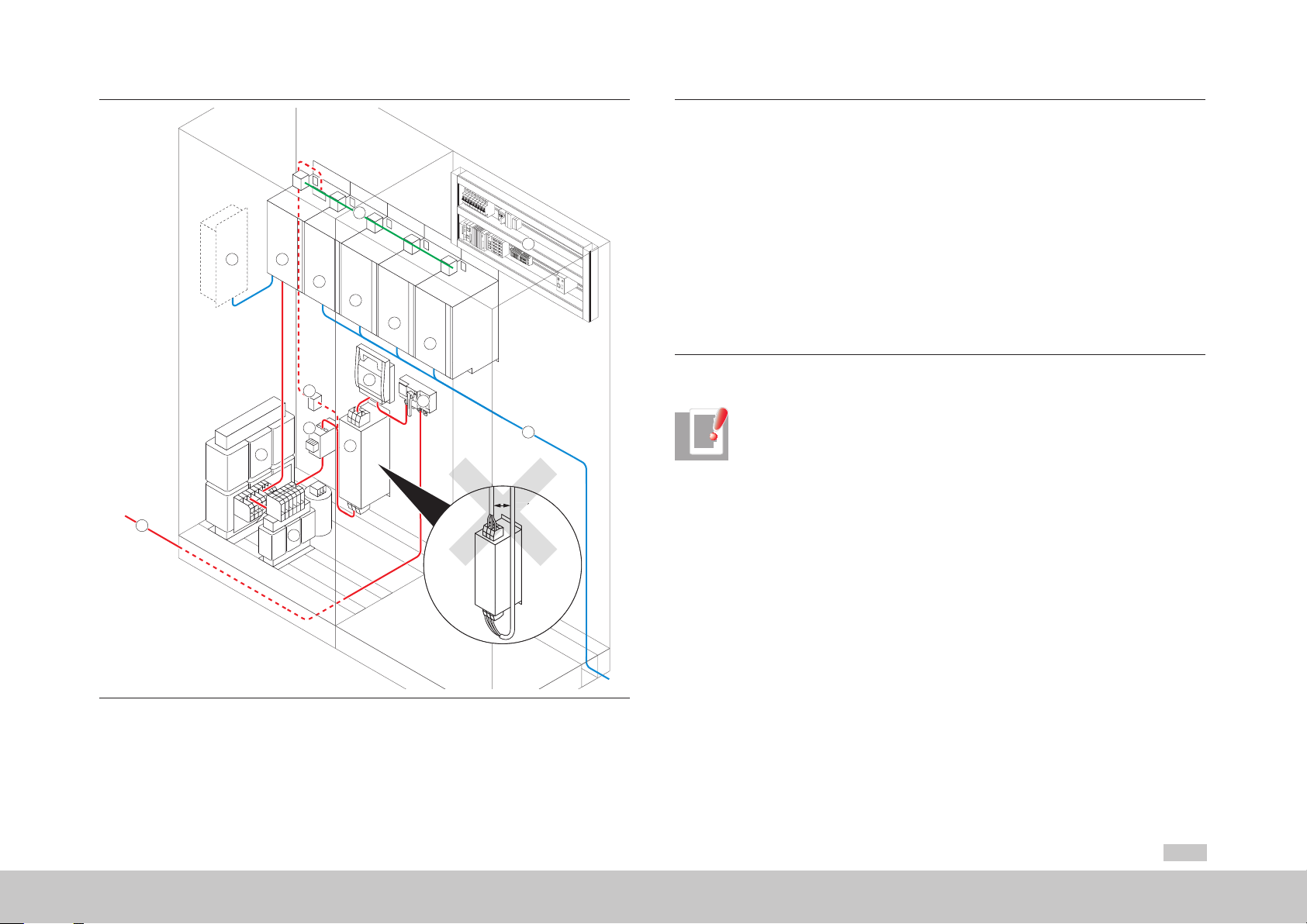
3.2.4 Shielding
Shielding should take account of the following points:
y Use shielded mains power, motor and signal cables as set out in Figure 3.7,
p.30. Use a cable type with double copper braiding, with 60 - 70%
coverage, for all shielded connections.
y Apply the shield on both sides, across a wide area. Extending the shield to the
earthing point by a wire (pigtail) will reduce the shielding effect by as much as
90%.
Figure 3.1 Shield connection CORRECT
Figure 3.2 Shield connection INCORRECT - do not use an extension wire to the earthing point
(pigtail)
Figure 3.3 Power Supply Unit shield connection
y Do not strip the shield too early.
y Shields must not be used for current carrying, such as replacing the N or PE
conductor.
y The shielding effect can be improved by laying in metal ducts/pipes.
y If very large cable cross-sections have to be installed, shielded single wires may
also be laid instead of shielded cables.
y Shields must be applied on at least one side. Multi-layer application is
recommended, otherwise equipotential bonding currents may flow through
widespread systems. If long earth connections are subject to interference, they
can be made by way of coupling capacitors. This enables a high-frequency
connection to discharge interference, without transmitting the 50Hz
component.
y The choke bases must have good contact with the cabinet earth. The contact
area must be metallically bright, in order to make a good earth connection to
the cabinet earth.
moog
ID no.:CA97556-001 Date:03/2015
Electrical installation
Programmable Multi-Axis Servo Drive Power Supply Unit Operation Manual
27
Page 28

Electrical installation
X12
moog
ID no.:CA97556-001 Date:03/2015
3.3 Overview of connections
The following shows the layout with the corresponding positions of connectors and
terminals. To aid orientation, the connectors and terminals are labelled by abbreviations.
3.3.1 Layout, size 5 (G396-026 and G396-050)
X11
PE
X21
X9/X10
D1/D2
T1/T2
X1
X2
X3
X4
SW
HW
X5
Option 1
Programmable Multi-Axis Servo Drive Power Supply Unit Operation Manual
3.3.2 Layout, size 6A (G396-075 and G396-110)
SW
HW
PE
X21
X11
X9/X10
D1/D2
T1/T2
X1
X2
X3
X4
X5
Option 1
28
Figure 3.4 Layout, size 5
X12
Figure 3.5 Layout, size 6A
Page 29

USB 1. 1
MMC-Slo t
ISD00
ISD01
ISD02
OSD02
Relai s
ENPOENPO
Control
Ser vice
interface
Ser vice
interface
ISDSH
ISA00+
ISA00ISA01+
ISA01-
+24V( U
H
)
3
4
5
6
10
15
16
17
9
23
24
22
RSH
12
11
1
2
14
13
ZK
�
ZK+
L3
L2
L1
ISD03
ISD04
ISD05
18
19
20
ISD0621
OSD01
8
OSD00
7
OSD04
DGND
DGND
X
12
X
4
X
10
X
9
X
2
D
1
,
D
2
T
1
,
T
2
X
1
Ether net
X
3
+
�
X
21
L2
L3
N
L1
HREL
MMC
MultiMediaCar d
INSER T
–
+
–
+
1
2
1
2
Mains contactor
X
11
DC link cables
(Size 6A protected)
24 V DC supply for
control electronics (U
V
)
DC link
Top
Bottom
Front
Option 1
Communication
fieldbuses
KTY temp. sensor
of step-up choke
X
5
RB
�
RB+
Braking resistor
Power connection
Mains synchronisation
and precharge
3.3.3 Overview of connections, size 5 and size 6A
Figure 3.6 Overview of connections, size 5 and size 6A
moog
Electrical installation
ID no.:CA97556-001 Date:03/2015
No. Designation Function Page
D1, D2
T1, T2
Option 1
X10, X 9
7-segment display Device status display p.64
Pushbuttons Service functions p.59
Communications
Slot for MMC removable
X1
storage device
USB 1.1 port Service interface, Plug & Play connection to PC p.47
X2
Ethernet port Service interface, fast TCP/IP port (RJ45) p.47
X3
Control connections
X4
Temperature monitor
X5
connection
Optional module for fieldbusses, e.g. SERCOS,
PROFIBUS-DP, EtherCAT or CANopen
Enables firmware download without PC for example p.63
8 digital inputs, 3 digital outputs, 1 additional relay
output
KTY temperature sensor of step-up choke p.48
Connection of control supply UVSupply voltage for control electronics of servo drive,
24 V DC
X11
DC power supply
Connection of DC power supply (size 6A protected),
PE connection
AC power connection (supply and mains feedback),
X12
Power connection
PE connection with shield, braking resistor,
(DC power supply connection, Power Supply Unit
size 6A to Multi-Axis Servo Drive size 6A)
X21
SW, HW
Connection of mains
synchronisation/DC link
precharge; auxiliary relay
Rating plates Software and Hardware rating plates p.4
Mains synchronisation, DC link precharge, mains
connection after precharge
Shield connection to earth Possible via shield (optional) -
Table 3.1 Key to overview of connections, size 5 and size 6A
Programmable Multi-Axis Servo Drive Power Supply Unit Operation Manual
p.47
p.44
p.36
p.40
p.41
p.38
p.38
p.47
p.43
p.37
29
Page 30

Electrical installation
moog
ID no.:CA97556-001 Date:03/2015
3.3.4 Connection diagram, size 5
8 9 10
L1
L1.1
L2
L2.1
L3
L3.1
L2
L1
6
L2.1
L1.1
5
L2
L1
4
L2.1
L1.1
3
2
1
L3
L3.1
L3
L3.1
Programmable Multi-Axis Servo Drive Power Supply Unit Operation Manual
30
Key
L1.1
L1
L2.1
L2
L3.1
L3
7
11
24 V DC
PE
12
13
maximum 8 A
14
nc
EtherCAT
+ �
X11X11
Multi-Axis
Servo Drive
X9/10X9/10
X12X12
UVW
HREL
15
X5
L1 L2
L3 N
X21
Power Supply Unit
16 19 19
X12
L1 L2
+ �
X11
L3
�+ �+
X9/10
ZK RB
+ �� +
+ � �+ �+�+ �+
Multi-Axis
Servo Drive
EtherCAT
UVW
17
1) Mains f uses
2) Mains supply/eme rgenc y stop
3) Shiel d plates (grey)
4) Step-up choke with KTY temperature sensor
5) Above a ca ble length of >500 mm (19.69 in)
shielded cables should be used
6) Input choke with membrane cap acitor
7) Mains contactor (af ter precharge by HR EL)
8) Mains fi lter
9) Short-circuit-proof cables
10) Circuit-breaker
11) Multi-axis sy stem On/Off
12) External 24 V DC control supply
13) Auxiliary contactor (precharge/synchronisation)
14) Connection of DC link pr echarge and mains
synchronisation
15) Floating contact:250 V AC/5 A or 30 V DC/6 A
(active wh en precharge complete)
16) Power Supply Unit size 5
17) AC power co nnecti on
18) Brakin g resistor w ith tempe rature sens or
19) Multi-Axis Servo Drive
20) Cabinet
21) Field
L1 L2 L3 PE
Figure 3.7 Power Supply Unit connection diagram (schematic view)
20
�
18
Motor
3~
Motor
3~
Page 31

NOTE:
Risk of Power Supply Unit destruction by incorrect wiring. Figure 3.7 shows
!
only a schematic view of the connection layout. The positions of the terminals
may vary according to device.
NOTE:
You will find a selection of potential mains contactors, circuit-breakers and
fuses in sectionA, p.66.
moog
ID no.:CA97556-001 Date:03/2015
Electrical installation
Programmable Multi-Axis Servo Drive Power Supply Unit Operation Manual
31
Page 32

Electrical installation
moog
ID no.:CA97556-001 Date:03/2015
3.3.5 Connection diagram, size 6A
8 9 10
L1
L1.1
L2
L2.1
L3
L3.1
L3
L2
L1
6
L3.1
L2.1
L1.1
5
L3
L2
L1
4
L3.1
L2.1
L1.1
3
2
1
Programmable Multi-Axis Servo Drive Power Supply Unit Operation Manual
32
Key
L1.1
L1
L2.1
L2
L3.1
L3
7
11
24 V DC
12
13
maximum 8 A
14
nc
HREL
15
X5
L1 L2
L3 N
X21
Power Supply Unit
16 19 19
X12
L1 L2
+ �
X11
L3
�+ �+
X9/10
ZK RB
+ �� +
+ �
X11
Multi-Axis
Servo Drive
EtherCAT
UVW
EtherCAT
+ �
X11
Multi-Axis
Servo Drive
�+ �+�+ �+
X9/10X9/10
X12X12
UVW
17
1) Mains f uses
2) Mains supply/eme rgenc y stop
3) Shiel d plates (grey)
4) Step-up choke with KTY temperature sensor
5) Above a ca ble length of >500 mm (19.69 in)
PE
shielded cables should be used
6) Input choke with membrane cap acitor
7) Mains contactor (af ter precharge by HR EL)
8) Mains fi lter
9) Short-circuit-proof cables
10) Circuit-breaker
11) Multi-axis sy stem On/Off
12) External 24 V DC control supply
13) Auxiliary contactor (precharge/synchronisation)
14) Connection of DC link pr echarge and mains
synchronisation
15) Floating contact:250 V AC/5 A or 30 V DC/6 A
(active wh en precharge complete)
16) Power Supply Unit size 6A
17) AC power co nnecti on
18) Brakin g resistor w ith tempe rature sens or
19) Multi-Axis Servo Drive
20) Cabinet
21) Field
L1 L2 L3 PE
Figure 3.8 Power Supply Unit connection diagram (schematic view)
20
21
�
18
Motor
3~
Motor
3~
Page 33

NOTE:
1.
2.
Risk of Power Supply Unit destruction by incorrect wiring. Figure 3.8 shows
!
only a schematic view of the connection layout. The positions of the terminals
may vary according to device.
NOTE:
You will find a selection of potential mains contactors, circuit-breakers and
fuses in sectionA, p.66.
3.4 Connection of PE conductors
The PE conductor cross-section depends on the cross-section of the outer conductor,
and is defined as follows in IEC/EN61800-5-1. The leakage current is > 3.5 mA. Use PE
conductors with a cross-sectional area of ≥10mm2 (0.02in2) (Cu).
Cross-sectional area of outer conductors
[mm2 (in2)]
Q ≤ 16 (0.03) Q
16 (0.03) < Q ≤ 35 (0.05) 16 (0.03)
35 (0.05) < Q Q/2
Table 3.2 PE conductor cross-section
3.4 .1 PE conductor (X11)Power Supply Unit size 5
Minimum cross-sectional area
of corresponding PE conductor [mm2 (in2)]
moog
ID no.:CA97556-001 Date:03/2015
Earth each Power Supply Unit and Multi-Axis Servo Drive!
Connect the PE terminal X11/PE of the Power Supply Unit to the PE terminals X11/PE of the butt-
Connect the PE terminal X11/PE of the Power Supply Unit directly to the PE rail (main earth) in
the cabinet.
Select the PE conductor cross-section as per Table 3.2.
Use a suitable PE conductor for the purpose (screw M5). Also comply with local and national
regulations and conditions.
mounted Multi-Axis Servo Drives in series.
Use the ready made-up PE conductors.
Programmable Multi-Axis Servo Drive Power Supply Unit Operation Manual
33
Electrical installation
Page 34

Electrical installation
1.
2.
X12
PE
PE
X11
PE
X11
PE
X11
PE
X11
PE
X11
Multi-Axis Servo Drive size 4
Multi-Axis Servo Drive size 3
Multi-Axis Servo Drive size 2
Multi-Axis Servo Drive size 1
Power Supply Unit
size 5
moog
Figure 3.9 Schematic: Connection of the PE conductor
ID no.:CA97556-001 Date:03/2015
Programmable Multi-Axis Servo Drive Power Supply Unit Operation Manual
3.4.2 PE conductor (X11)Power Supply Unit size 6A
Earth each size 6A supply unit and each size 6A Multi-Axis Servo Drive separately.
Connect the PE terminal X11/PE of the Power Supply Unit directly to the PE rail (main earth) in
the cabinet.
Use a suitable PE conductor for the purpose (screw M8). Also comply with local and national
regulations and conditions.
Select the PE conductor cross-section as per Table 3.2, p.33.
Earth all other Multi-Axis Servo Drives size 5 to size 1 via a common PE conductor! Connect all
other PE terminals X11/PE of the butt-mounted Multi-Axis Servo Drives in series.
Connect the PE terminal X11/PE of the first butt-mounted Multi-Axis Servo Drive to the PE rail
(main earth) in the cabinet.
Use a suitable PE conductor for the purpose. Also comply with local and national regulations and
conditions.
Use the ready made-up PE conductors.
34
Figure 3.10 Detail: Connection of the PE conductor
Page 35

3.4.3 PE conductor components
1.
X12
PE
PE
X11
PE
X11
PE
X11
PE
X11
PE
X11
PE
X11
Multi-Axis Servo Drive size 5
Multi-Axis Servo Drive size 4
Multi-Axis Servo Drive size 3
Multi-Axis Servo Drive size 2
Multi-Axis Servo Drive size 1
Power Supply Unit
size 6A
Figure 3.11 Schematic: Connection of the PE conductor
Connect the PE terminals of all other components, such as mains filters etc., in star configu-
ration to the PE rail (main earth) in the cabinet. See Figure 3.7, p.30.
Also comply with local and national regulations and conditions.
WARNING!
The chokes have no PE connection. They are intended solely for installation in
a cabinet, as with IP00 protection they offer no protection against direct or
indirect touch contact.
3.5 Electrical isolation method
The control electronics, with its logic (µP), the inputs and outputs, are electrically
isolated from the power section (mains supply/DC link). All control terminals are
designed as safety extra-low voltage/protective extra-low voltage (SELV/PELV) circuits
and must only be operated with voltages from 5 V to 50 V, as per the relevant
specification. This provides reliable protection against electric shock on the control side.
The control electronics therefore need a separate control supply, compliant with the
requirements of a SELV/PELV.
The opposite overview shows the potential supplies for the individual terminals in detail.
This concept also delivers higher operational safety and reliability of the Power Supply
Unit.
SELV = Safety Extra Low Voltage
Figure 3.12 Detail: Connection of the PE conductor
moog
ID no.:CA97556-001 Date:03/2015
Electrical installation
PELV = Protective Extra Low Voltage
Programmable Multi-Axis Servo Drive Power Supply Unit Operation Manual
35
Page 36

Electrical installation
V
moog
USB1.1
X2
X4/15
ISD00
ISD01
ISD02
ISD03
ISD04
ISD05
X4/21
ISD06
X4/10
ENPO
X4/22
ISDSH
X4/14
F1
X4/7
ϑ
F2
ϑ
F3
ϑ
F4
ϑ
DGND
DGND
OSD00
U
X4/2
H
X4/13
X4/1
ID no.:CA97556-001 Date:03/2015
µP
GNDµP
I
LIM
DGND
I
LIM
DGND
I
LIM
DGND
I
LIM
DGND
µP
PE
V
µP
GNDµP
GNDµP
36
Ethernet
X3
Programmable Multi-Axis Servo Drive Power Supply Unit Operation Manual
3.6 Connection of supply voltages
The power supply for the Power Supply Unit is separated into the supplies for
control and power sections. The control supply must always be connected first, so
Mains synchronisation
X21
that activation of the Power Supply Unit can first be checked and the device can be
parameterised for the planned application.
3.6 .1 Control supply 24VDC (X9, X10) for size 5 and size 6A
X5/ϑ +
KTY temp. sensor
of step-up choke
X5/ϑ −
X4/3
X4/4
X4/5
X4/6
ISA00+
ISA00-
ISA01+
ISA01-
X9/+
X9/-
X10/+
X10/-
U
U
V
Supply for
control electronics
24 V DC
V
maxiumum 10 A
L1 L2
HREL
L3 N − +− +
X21X9/10
Figure 3.14 Connection of control supply
WARNING!
Hazardous voltage may be applied to the device, even if the device does not
A/D
GNDµP
A/D
GNDµP
V
µP
show any visual signs or emit any audible signals (e.g. with mains voltage
applied to terminal X12) and missing control voltage (+24V on X9, X10)!
+ −
X11
24 V DC
+ −+ − − +− +− +− +
X11X11
X9/10X9/10
DGND
DGND
DGND
PE GNDµP
Complex, in
DGND RC element Polyswitch
part nonlinear,
impedance
OSD01
OSD02
X4/8
X4/9
Figure 3.13 Electrical isolation method, size 5 and size 6A
ATTENTION!
Take suitable measures to provide adequate cable protection (e.g. fusing
!
X4/12
RSH
X4/11
GNDµP
F3
GNDµP
ϑ
X4/23
X4/24
OSD04
10AgG). If the permissible current capacity is exceeded, an additional
separate control supply must be connected.
NOTE:
The external control supply also supplies the digital inputs and outputs as well
as the control section (I
CONTROLSECTION
+ I
). Also pay attention to the current
I/O
demand on start-up and in operation. See sectionA.2, p.6969.
Page 37

X21
L
L1
NOTE:
X9
+
−
X10
1/+
−
Do not use the plug as a "switch" for a reset.
3.6.2 Precharge and mains synchronisation (X21) for size 5 and size 6A
Specification of control supply
• UV = 24 V DC -20 % +10 %, stabilised and smoothed.
• Max. Start-up/continuous current see Table A.7, p.69
1/
Control
supply
Table 3.3 Specification of control supply
2/
• Back-up fuse rating for terminal maximum10A
• Internal polarity reversal protection
• The power supply unit used must have a safe and reliable isolation against
the mains system according to EN50178 or IEC/EN61800-5-1.
• Internally wired with X10
• Internally wired with X9
2/
The DC link is precharged via terminal X21/L1,L2,L3 (Figure 3.15, p.38). At a defined
DC link voltage the contact of the internal relay on terminal X21/HREL is closed. The
mains contactor closes and switches the supply system to terminal X12/ L1,L2,L3. The
Power Supply Unit is synchronised with the mains via terminal X21/L1,L2,L3. Technical
data of mains contactor see sectionA.11, p.73.
ATTENTION!
The cable must be protected by a circuit-breaker. Ensure the correct phase
!
angle of the conductors during installation (Figure 3.15, p.38). Technical
data of circuit-breaker see A.12, p.73.
Specification of precharge and mains synchronisation X21
• U = 400/460/480 V AC
Precharge and
mains synchronisation
(L1, L2, L3)
Auxiliary relay
(HREL)
Table 3.4 Specification of precharge and mains synchronisation X21
• I
= 20 A (falling over a period of < 1.5s)
Precharge
• I
L2
L3
• Cable cross-section = 1.0 ... 1.5mm2 (0.002 ... 0.0023in2)
N
HRE
• (N: Not used)
• Max values of connection
• U
Synchronisation
= 30VDC / I
Max
< 100 mA
Max
= 6A
moog
Electrical installation
ID no.:CA97556-001 Date:03/2015
Programmable Multi-Axis Servo Drive Power Supply Unit Operation Manual
37
Page 38

Electrical installation
moog
ID no.:CA97556-001 Date:03/2015
3.6.3 Mains connection 400/480VAC (X12) for size 5 and
Size6A
8 9 10
L1.1
L1
L1.1
L2
L2.1
L3
L3.1
L2
L1
6
L2.1
L1.1
5
L2
L1
4
L2.1
L1.1
3
2
1
L1
L2.1
L2
L3.1
L3
7
L3
14
L3.1
HREL
15
L3
L3.1
X5
17
nc
L1 L2
L3 N
X21
Power Supply Unit
16
X12
L1 L2
13
+ �
L3
11
24 V DC
X9/10X11
ZK RB
+ �� +
�+ �+
Programmable Multi-Axis Servo Drive Power Supply Unit Operation Manual
1) Mains f uses
2) Mains supply/eme rgenc y stop
3) Shiel d plates (grey)
4) Step-up choke with KTY temperature sensor
5) Above a cable length of >500 mm shielded cables should
be used
6) Input choke with membrane cap acitor
7) Mains contactor (af ter precharge by HR EL)
8) Mains fi lter
9) Short-circuit-proof cables
12
10) Circuit-breaker
11) Multi-axis sy stem On/Off
12) External 24 V DC control supply
13) Auxiliary contactor (precharge/synchronisation)
14) Connection of DC link pr echarge and mains syn chronisation
15) Floating contact:250 V AC/5 A or 30 V DC/6 A (ac tive
when precharge complete)
16) Power Supply Unit size 6A
17) AC power co nnecti on
18) Braking resistor
38
Figure 3.15 Connection of mains supply (schematic view)
ATTENTION!
Danger to life! Never wire or disconnect electrical connections while they are
!
live. Always disconnect the power before working on the device. Dangerously
high voltages ≥50V (capacitor charge) may still be present 10minutes after
the power is cut to the size 5 and size 6A. The discharge time depends on the
number of drives connected to the multi-axis system. So check that no voltage
is connected!
L1 L2 L3 PE
�
18
Page 39

Procedure:
1.
2.
Mains connection conditions
Define the cable cross-section depending on the maximum current and ambient temperature.
Wire the Power Supply Unit with the mains supply as shown in Figure 3.15.
Cable cross-section according to local regulations and conditions.
Use shielded cables, as shown in Figure 3.15.
Do not switch on the power!
For more information on connection of the terminal X21 precharge see section3.6.2, p.37.
For more information on connection of the components see section3.15, p.48 ff.
Technical data of components see sectionA.7, p.72 ff.
ATTENTION!
If local regulations require the installation of a residual current operated
!
protective device, the following applies: In case of a fault the Power Supply
Unit is able to generate DC fault currents without zero crossing. The Power
Supply Unit therefore must only be operated with RCDs1) of type B for AC
fault currents, pulsating and smooth DC fault currents which are suitable for
servo drive operation - see IEC60755. RCMs2) can additionally be used for
monitoring purposes.
1) Residual Current Protective Device
2) Residual Current Monitor
Terminal X12/L1,L2,L3
Size Size 5 Size 6A
Device G396-026 G396-050 G396-075 G396-110
50 ... 150 mm2
Cable connection capacity
Tightening torque
1) Flexible cable with ferrule
2) Flexible cable with or without ferrule
3) With o ptional inserts for G396- 075-xx x-xxx to reduce the d iameter
0.5 ... 25 mm2 (0.0008 ... 0.04 in2)
(AWG20...AWG4)
2.5 ... 4.5Nm 25 ... 30Nm
1)
(0.08 ... 0.23 in2)
(10 ... 95 mm2
(0.02 ... 0.15 in2))3)
(AWG0...
AWG5/0)
2)
50 ... 150 mm2
(0.08 ... 0.23 in2)
(AWG0...
AWG5/0)
To ensure undisturbed operation on the supply system with a Power Supply Unit, a
minimum requirement for the short-circuit power at the mains connection applies. The
transition at the mains filter is defined as the mains connection.
The requirement must be met in order to avoid impairment at the Power Supply Unit
and interference with other devices connected in parallel to this mains connection, and
to enable a reliable operating state.
The term “short-circuit power” is a theoretical value of an apparent power occurring in a
current network when a short-circuit is caused at a transfer point.
MSD Power Supply
G396-026
(Sn = Pn = 26kW)
G396-050
(Sn = Pn = 50kW)
G396 -075
(Sn = Pn = 75kW)
G3 9 6 -110
(Sn = Pn = 110kW)
1) Rsc is defi ned as the short-circuit ratio of th e short- circuit power (Sk) at the mains connec tion to the rated power (Sn) of
the Power Supply Unit ( Rsc = Sk/Sn).
Table 3.5 Mains connection conditions
2)
Short-circuit
ratio Rsc
1)
30 ... 50
Minimum requirements for the short-circuit
power at the mains connection for undisturbed
operation
800 kVA ... 1300kVA
1500 kVA ... 2500kVA
2250 kVA ... 3750kVA
3300 kVA ... 5500kVA
moog
ID no.:CA97556-001 Date:03/2015
Electrical installation
Programmable Multi-Axis Servo Drive Power Supply Unit Operation Manual
39
Page 40

Electrical installation
moog
ID no.:CA97556-001 Date:03/2015
Note the following points:
y Switching the mains power:
− In case of too frequent switching of the precharge, the unit protects itself
by high-resistance isolation from the system. After a rest phase of a few
minutes the device is ready to start once again.
y TN network and TT network: Permitted without restriction.
y IT network (isolated neutral point): Not permitted!
− In case of an earth fault the electrical stress is approximately twice as high.
Clearances and creepages to IEC/EN61800-5-1 are no longer maintained.
y For more information on permissible current loads, technical data and ambient
conditions refer to the appendix.
NOTE:
Please be aware that the Power Supply Unit is not rated for electromagnetic
environment class 3 (IEC/EN61000-2-4). Further measures are essential in
order for that environment class to be attained! For further information please
consult your project engineer.
Programmable Multi-Axis Servo Drive Power Supply Unit Operation Manual
3.7 DC power supply connection
ATTENTION!
Use only the supplied DC link cable for the electrical connections between the
!
devices. If other cables are used, Moog can provide no guarantee of stable
and safe operation.
ATTENTION!
The cover over terminal X11 (DC connection) on size 1 to size 5 must be closed
!
after installing the ready made-up cables. Operation without the cover is not
permitted.
NOTE:
Prior to commissioning, the value of the connected supply voltage must be set
in the servo drive. For more details see section4.2.10, p.57.
Terminal X11
Size Size 5 Size 6A
Device G396-026 G396-050 G396-075 G 396-110
Cable connection capacity
Use only the preassembled connecting
Tightening torque
1) Flexible cable with or without ferrule
cables supplied.
(Hole diameter 5.5 mm (0.22 in))
2.5 ... 4.5Nm 25 ... 30Nm
Use the ready made-up cables sup-
plied or 35 ... 95 mm2
(0.05 ... 0.15 in2)
(AWG2...AWG3/0)
1)
40
Page 41

3.7.1 DC power supply connection(X11) size 5
1.
2.
3.
Connect terminal X11/+ of the Power Supply Unit to terminal X11/+ of the next butt-mounted
Connect terminal X11/- of the Power Supply Unit to terminal X11/- of the next butt-mounted
Connect the touch protection to DC link terminals X11.
+
–
X11X11 X11X11 X11
Power Supply Unit
size 5
Multi-Axis Servo Drive.
On the Multi-Axis Servo Drive connect the DC power supply conductor to the next butt-mounted
Multi-Axis Servo Drive.
Use the ready made-up DC power supply cables.
Multi-Axis Servo Drive.
On the Multi-Axis Servo Drive connect the DC power supply conductor to the next butt-mounted
Multi-Axis Servo Drive.
Use the ready made-up DC power supply cables.
For more information refer to the Multi-Axis Servo Drive Operation Manual.
+ +
–––
+
+
–
Figure 3.17 Detail: DC power supply connection, size 5
Multi-Axis Servo Drice size 4
Figure 3.16 Schematic: DC power supply connection, size 5
moog
ID no.:CA97556-001 Date:03/2015
Multi-Axis Servo Drice size 3
Electrical installation
Multi-Axis Servo Drice size 2
Multi-Axis Servo Drice size 1
Programmable Multi-Axis Servo Drive Power Supply Unit Operation Manual
41
Page 42

Electrical installation
1X
1.
2.
3.
moog
ID no.:CA97556-001 Date:03/2015
3.7. 2 DC power supply connection (X11) size 6A
Size 6A connection to smaller Multi-Axis Servo Drives
Connect terminal X11/+ of the Power Supply Unit to terminal X11/+ of the next butt-mounted
Connect terminal X11/- of the Power Supply Unit to terminal X11/- of the next butt-mounted
Connect the touch protection to DC link terminals X11.
Multi-Axis Servo Drive.
Use the ready made-up DC power supply cables.
Take off the shrink tubing on the round end.
Use the longer conductor for servo drives butt-mounted on the right.
Use the shorter conductor for servo drives butt-mounted on the left.
On the Multi-Axis Servo Drive connect the DC power supply conductor to the next butt-mounted
Multi-Axis Servo Drive.
Multi-Axis Servo Drive.
Use the ready made-up DC power supply cables.
Take off the shrink tubing on the round end.
Use the shorter conductor for servo drives butt-mounted on the right.
Use the longer conductor for servo drives butt-mounted on the left.
On the Multi-Axis Servo Drive connect the DC power supply conductor to the next butt-mounted
Multi-Axis Servo Drive.
For more information refer to the Multi-Axis Servo Drive Operation Manual.
Programmable Multi-Axis Servo Drive Power Supply Unit Operation Manual
+
–
+
X11 X11
Power Supply Unit
size 6A
Figure 3.18 Schematic: Size 6A DC power supply connection to smaller Multi-Axis Servo Drives
–– –
Multi-Axis Servo Drice size 5
+ +
–
X11X11 X1
Multi-Axis Servo Drice size 4
Multi-Axis Servo Drice size 3
+
+
–
11
Multi-Axis Servo Drice size 1
Multi-Axis Servo Drice size 2
42
Page 43

+
1X11 X11X11
+
–– –
+
–
+
Multi-Axis Servo Drive size 4
Multi-Axis Servo Drive size 3
Multi-Axis Servo Drive size 2
Multi-Axis Servo Drive size 1
1.
2.
3.
X11
X1
+
–
+
–
–
X11
–
+
X11
+
Figure 3.19 Detail: Size 6A DC power supply connection to smaller Multi-Axis Servo Drives
Size 6A connection to size 6A Multi-Axis Servo Drives
Connect terminal X12/ZK+ of the Power Supply Unit to terminal X11/ZK+ of the next butt-
Connect terminal X12/ZK- of the Power Supply Unit to terminal X11/ZK- of the next butt-
Connect the touch protection to DC link terminals X11.
mounted Multi-Axis Servo Drive size 6A.
Use dedicated cables for the purpose.
The connection of the DC link must be made with parallel cables. The conductor cross-section
must be at least 50 mm2 (0.08 in2) (CU). The cables must be short-circuit and earth fault
proof, and shielded. Twist the cables or use a shield tube. A length of 2 m (6.56 ft) must not
be exceeded. If other cables are used, Moog can provide no guarantee of stable and safe
operation.
On the Multi-Axis Servo Drive connect the DC power supply conductor to the next butt-mounted
Multi-Axis Servo Drive.
mounted Multi-Axis Servo Drive size 6A.
On the Multi-Axis Servo Drive connect the DC power supply conductor to the next butt-mounted
Multi-Axis Servo Drive.
Use dedicated cables for the purpose.
For more information refer to the Multi-Axis Servo Drive Operation Manual.
Power Supply Unit
size 6A
X12
Figure 3.20 Schematic: DC power supply connection size 6A to size 6A
ZK
+L3L2L1PE –
RB
-
+
Multi-Axis Servo Drive size 6A
Multi-Axis Servo Drive size 5
moog
ID no.:CA97556-001 Date:03/2015
Electrical installation
Programmable Multi-Axis Servo Drive Power Supply Unit Operation Manual
43
Page 44

Electrical installation
REL
REL
ISDSH
ISD06
ISD05
ISD04
ISD03
ISD02
ISD01
ISD00
+24V
DGND
RSH
RSH
ENPO
OSD02
OSD01
OSD00
ISA1-
ISA1+
ISA0-
ISA0+
+24V
DGND
X4
4.
5.
6.
1.
2.
3.
moog
ID no.:CA97556-001 Date:03/2015
3.8 Control connections (X4)
Check whether a complete device setup is already available, i.e. whether the drive has already
If this is the case, a special control terminal assignment applies.
Choose a terminal assignment.
Note the following points:
been configured.
Please contact your project engineer to obtain the terminal assignment!
Wire the control terminals with shielded cables.
The following is strictly required: 24 VDC on X4/22 and ENPO X4/10 as start signal.
Earth the cable shields over a wide area at both ends.
Conductor sizes fixed: 0.2 to 1.5 mm2 (0.0003 to 0.0023 in2)
Flexible conductor sizes with ferrule: 0.2 to 1.5 mm2 (0.0003 to 0.0023 in2)
Keep all contacts open
(inputs inactive).
Check all connections again!
Continue with commissioning in section4.2.10, p.57.
y Always wire the control terminals with shielded cables.
y Lay mains, motor, signal, DC power supply and braking resistor cables isolated
from each other. Observe a minimum clearance of 200 mm (7.87 in).
y A cable type with double copper braiding, with 60 - 70% coverage, must be
used for all shielded connections.
Programmable Multi-Axis Servo Drive Power Supply Unit Operation Manual
3.8 .1 Specification of control connections
Des. Te rm. Specification Electrical isolation
Analog inputs
ISA0+
ISA0IS A1+
IS A1-
Digital inputs
ISD00
ISD01
ISD02
ISD03
ISD04
ISD05
ISDSH
ISD06 X4/21
ENPO X4/10
Digital outputs
OSD00
OSD01
OSD02
Table 3.6 Specification of control connections
X4/3
X4/4
X4/5
X4/6
X4 /15
X4/16
X4 /17
X4/18
X4/19
X4/20
X4/22
X4/7
X4/8
X4/9
No function No
• Frequency range < 500 Hz
• Terminal scanning cycle = 1 ms
• Switching level Low/High: ≤ 4.8 V / ≥ 18 V
• at 24 V typ. 3 mA
• Frequency range ≤500Hz
• Switching level Low/High: ≤ 4.8 V / ≥ 18 V
• I
at 24V = 10mA, RIN approx. 3kΩ
max
• Internal signal delay time < 2 μs suitable as trigger
input for quick saving of actual position
• Frequency range < 500 Hz
• Reaction time approx. 10ms
• Switching level Low/High: ≤ 4.8 V / ≥ 18 V
• at 24 V typ. 3 mA
• Short-circuit proof
• I
=50mA, PLC-compatible
max
• Terminal scanning cycle = 1 ms
• High-side driver
Yes
Yes
Yes
Yes
44
24
12
23
11
22
10
21
9
20
8
19
7
18
6
17
5
16
4
15
3
14
2
13
1
Page 45

Des. Te rm. Specification Electrical isolation
REL
REL
ISDSH
ISD06
ISD05
ISD04
ISD03
ISD02
ISD01
ISD00
+24V
DGND
RSH
RSH
ENPO
OSD02
OSD01
OSD00
ISA1-
ISA1+
ISA0-
ISA0+
+24V
DGND
X4
X4:23
X4:24
Relay outputs
• Relay, 1 NO contact
• Functions selectable as in case of
digital outputs
REL
RSH
RSH
X4/23
X4/24
X4 /11
X4 /12
Auxiliary voltage
+ 24 V
X4/2
X4/14
• 25V / 1.0A AC, cos ϕ = 1
Yes
• 30V / 1.0A DC, cos ϕ = 1
• Switching delay approx. 10ms
• Cycle time 1 ms
No function Yes
• Auxiliary supply to feed the digital control inputs
• UH = UV-∆U (∆U typically approx. 1.2V), no
destruction in case of short-circuit
• (+24V -> GND), but device may briefly shut down.
• I
= 80 mA (per pin) with self-resetting circuit-
max
breaker (polyswitch)
Yes
24
23
22
21
20
19
18
17
16
15
14
13
Digital ground (earth)
DGND
X4/1
X4/13
• Reference earth for 24 V, with automatically resetting circuit-breaker (polyswitch)
Yes
Table 3.6 Specification of control connections
NOTE:
With high currents flowing through the earth terminals a high resistance
isolation from the device earth is required. This may cause incorrect response
of the drive (avoid ring currents in the wiring).
3.8.2 Standard terminal assignment
Terminal assignment with factory setting
DescriptionX4 X4
REL
24
REL
12
11
10
9
8
7
6
5
4
3
2
1
23
ISDSH
22
21
ISD06
20
ISD05
19
ISD04
18
ISD03
17
ISD02
16
ISD01
15
ISD00
14
+24 V
13
DGND
Figure 3.21 Control terminals default assignment (initial commissioning)
NOTE:
The STO (Safe Torque Off) safety function is not required for the
Power Supply Unit, as no motors are connected. In order to start the Power
Supply Unit, a jumper must be placed between X4/14 and X4/22. The STO
safety function is used in conjunction with a Multi-Axis Servo Drive.
Description
12
11
10
9
8
7
6
5
4
3
2
1
RSH
RSH
ENPO
OSD02
OSD01
OSD00
ISA1-
ISA1+
ISA0-
ISA0+
+24 V
DGND
ENPO
moog
Electrical installation
ID no.:CA97556-001 Date:03/2015
Programmable Multi-Axis Servo Drive Power Supply Unit Operation Manual
45
Page 46

Electrical installation
moog
ID no.:CA97556-001 Date:03/2015
3.9 Functions of the digital inputs
The following functions can be selected for digital inputs ISD00 to ISD06:
Value Value name Description
0 MPRO_INPUT_FS_OFF No function
1 MPRO_INPUT_FS_START Start loop control
2 MPRO_INPUT_FS_E_EXT External error on another device
3 MPRO_INPUT_FS_WARN External warning on another device
4 MPRO_INPUT_FS_RSERR Reset an error message
Table 3.7 Selectable functions of digital inputs ISD00 to OSD06
3.10 Functions of the digital outputs
The following functions can be selected for digital outputs OSD00 to OSD02:
Value Value name Description
0 OUTPUT_FS_OFF No function
1 OUTPUT_FS_ERR General error
2 OUTPUT_FS_ACTIV Control in function
3 OUTPUT_FS_S_RDY Device initialised
4 OUTPUT_FS_PRECHARGE_RDY Device precharged
5 OUTPUT_FS_C_RDY Device ready (DC link voltage present)
6 OUTPUT_FS_REF DC link voltage reference (setpoint) reached
7 OUTPUT_FS_E_FLW No function
8 OUTPUT_FS_LIMIT
9 OUTPUT_FS_UDC_GT_UDCX
10 OUTPUT_FS_P_LIM_ACTIV No function
11 OUTPUT_FS_UDC_LIM_ACTIV
DC link voltage reference limitation active (the voltage is
outside the defined range.)
Actual DC link voltage higher than defined in parameter
P-0740 Voltage threshold
DC link voltage reference limitation active (the voltage is
outside the defined range.)
Programmable Multi-Axis Servo Drive Power Supply Unit Operation Manual
Value Value name Description
12 OUTPUT_FS_I_LIM_ACTIV No function
13 OUTPUT_FS_ENMO No function
14 OUTPUT_FS_PLC No function
15 OUTPUT_FS_WARN General warning
16 OUTPUT_FS_WUV Warning: undervoltage in DC link (defined in P-0730[0,1])
17 OUTPUT_FS_WOV Warning: overvoltage in DC link (defined in P-0730[2,3])
18 OUTPUT_FS_WIIT
19 OUTPUT_FS_WOT_PTC
20 OUTPUT_FS_WOTI
21 OUTPUT_FS_WOTD
22 OUTPUT_FS_WLIS
23 OUTPUT_FS_WLVOLT
24 OUTPUT_FS_COM_1MS Setting outputs via COM Option in 1 ms cycle
25 OUTPUT_FS_COM_NC Setting outputs via COM Option in NC cycle
26 OUTPUT_FS_SH_S No function
27 OUTPUT_FS_BC_FAIL Brake chopper fail error (Error = LOW)
28 OUTPUT_FS_WLPOW Effective power limit exceeded (defined in P-0730[16,17] )
29 OUTPUT_FS_GRID_OK
Table 3.8 Selectable functions of digital outputs OSD00 to OSD02
Warning: I2t-power stage protection threshold reached
(defined in P-0730[6,7])
Warning: KTY sensor of step-up choke (defined in
P-0730[12 ,13])
Warning: heat sink temperature of Power Supply Unit
(defined in P-0730[08,9])
Warning: internal temperature in Power Supply Unit (defined
in P-0730[10,11])
Warning: apparent current limit value exceeded (defined in
P-0730[4,5])
Warning: DC link voltage limit value exceeded (defined in
P-0730[14 ,15 ])
Mains OK (frequency AND voltage within tolerance window
= high)
46
Page 47

3.11 Specification of USB port (X2)
3.14 Braking resistor (X12/RB)
The service and diagnostic interface X2 is executed as a USB V1.1 port. It is suitable only
for connection of a PC for commissioning, service and diagnosis purposes using the
Moog Dri veADm inist rAtor5 software.
Technical specification:
y USB 1.1 standard - full speed device port
y Connection via standard commercially available USB interface cable type A to
type B (see also Programmable Multi-Axis Servo Drive System (MSD) Ordering
Catalog)
3.12 Specification of Ethernet port (X3)
The service and diagnostic interface X3 is executed as an Ethernet port. It is suitable
only for connection of a PC for commissioning, service and diagnosis purposes using the
Moog Dri veADm inist rAtor5 software.
Technical specification:
y Transfer rate 10/100 MBits/s BASE-T
y Transfer profile conforming to IEEE802.3
y Connection via standard commercially available crosslink cable (see also
Programmable Multi-Axis Servo Drive System (MSD) Ordering Catalog)
3.13 Option 1
In regenerative operation, e.g. when braking the motor, power is routed into the DC
link of the multi-axis system and fed back via the Power Supply Unit to the mains.
If feedback to the mains is not possible (such as in the event of a power failure), the
internal braking transistor is activated and the regenerated power is converted into heat
by way of a braking resistor.
3.14 .1 Connection of the external braking resistor
DANGER!
Terminal RB+ is permanently switched to DC link potential (>300 V DC).
The connection is not protected inside the device. Never wire or disconnect
electrical connections while they are live. Always disconnect the power
before working on the device. Dangerously high voltages ≥50V (capacitor
charge) may still be present 10minutes after the power is cut to the size 5 and
size6A. The discharge time depends on the number of drives connected to
the multi-axis system. So check that no voltage is connected!
ATTENTION!
The external braking resistor must be monitored by the control. The
!
temperature of the braking resistor is monitored by a temperature watchdog
(Klixon). In the event of overheating the Power Supply Unit must be
disconnected from the mains supply.
Depending on the Power Supply Unit variant, option 1 is factory-configured with various
options. Field bus options such as EtherCAT or SERCOS are available.
You will find all available options in the Programmable Multi-Axis Servo Drive System
(MSD) Ordering Catalog. The user manuals for the respective options provide detailed
information on commissioning.
moog
ID no.:CA97556-001 Date:03/2015
Electrical installation
Programmable Multi-Axis Servo Drive Power Supply Unit Operation Manual
47
Page 48

Electrical installation
moog
ATTENTION!
y The external braking resistor can only be installed in conjunction with a
!
y Be sure to follow the installation instructions for the external braking
y The minimum permissible connection resistance of the Power Supply Unit
y The cable cross-section depends on the performance of the braking
y The braking resistor may radiate intensive heat. So be sure to keep the
ID no.:CA97556-001 Date:03/2015
Power Supply Unit without an internal braking resistor.
re sistor.
must not be infringed. Technical specifications for braking resistors see
Table A.2, p.66, Table A.5, p.68 and Table A.8, p.69.
re sistor.
braking resistor an adequate distance from adjacent assemblies, or install it
outside the cabinet.
Terminal X12/RB
Size Size 5 Size 6A
Device G396-026 G396-050 G396-075 G 396-110
Cable connection capacity
Tightening torque
1) Flexible cable with ferrule
2) Flexible cable with or without ferrule
0.5 ... 25 mm2 (0.0008 ... 0.04 in2)
(AWG20...AWG4)
2.5 ... 4.5Nm 6 ... 8Nm
1)
25 ... 50 mm2 (0.04 ... 0.08 in2)
(AWG4...AWG0)
2)
Programmable Multi-Axis Servo Drive Power Supply Unit Operation Manual
48
3.15 Overview of step-up choke connections
The following shows the layout with the respective positions and labelling of the
terminals. The temperature is evaluated with a KTY sensor via terminal X5. At +145°C
(+293°F) the Power Supply Unit is switched off. Technical data of step-up choke see
sectionA.7, p.72.
WARNING!
The choke has no PE connection. It is intended solely for installation in a
cabinet, as with IP00 protection they offer no protection against direct or
indirect touch contact.
DANGER!
The choke will reach temperatures of up to +145°C (+293°F) when in
!
continuous operation! Touching may cause serious burns. Touch the choke
only wearing protective gloves, or after allowing it to cool for a lengthy period
of time.
X12
ZK
L1
L2 L3
Figure 3.22 Connection of external braking resistor (example: size 6A)
+ −
RB
− +
ϑ
Page 49

L1
ϑ+
L1.1 L2 L2.1 L3 L3.1
3.16 Overview of input choke connections
−
L1 L1.1 L2 L2.1 L3 L3.1
ϑ
+−
The following shows the layout with the respective positions and labelling of the
terminals. Technical data of input choke see sectionA.8, p.7272.
L1 L1 .1 L2 L2.1 L3 L3.1
L1.1 L2.1 L3.1
L1.1 L2.1 L3.1
L1
L2 L3
Figure 3.23 Step-up choke connections for size 5 and size 6A
+ϑ
−ϑ
For size Size 5 Size 6A
For model G396-026 G396-050 G396-075 G39 6 -110
Power connections
1.5 .. 16 mm2
Cable connection capacity (flexible without/
with ferrule)
Tightening torque
KTY sensor
Cable connection capacity (flexible, with ferrule)
Tightening torque
Table 3.9 Step-up choke connections
(0.0023 ... 0.025 in2)
1.5 .. 16 mm2
(0.0023 ... 0.025 in2)
(AWG18...AWG6)
1.5 ... 2.4Nm
(13.2...21.2lb-in)
2.5 ... 35 mm2
(0.004 ... 0.05 in2)
2.5 ... 35 mm2
(0.004 ... 0.05 in2)
(AWG12...AWG0)
4 ... 5Nm
(35.4...44.2lb-in)
0.5 ... 2.5 mm2 (0.0008 ... 0.004 in2)
(AWG30...AWG12)
0.4 ... 0.8Nm (3.5 ... 7.0lb-in)
2.5 ... 35 mm2
(0.004 ... 0.05 in2)
2.5 ... 35 mm2
(0.004 ... 0.05 in2)
(AWG12...AWG0)
4 ... 5Nm
(35.4...44.2lb-in)
16 ... 120 mm2
(0.025 ... 0.19 in2)
16 ... 90 mm2
(0.025 ... 0.15 in2)
(AWG4...
kcmil250)
12 ... 20Nm
(106.2...177lb-in)
L1 L2 L3
Figure 3.24 Input choke connections for size 5 and size 6A
For size Size 5 Size 6A
For model G396-026 G396-050 G396-075 G396-110
Power connections
1.5 .. 16 mm2
Cable connection capacity
(flexible without/
with ferrule)
Tightening torque
Table 3.10 Input choke connections
(0.0023 ... 0.025 in2)
1.5 .. 16 mm2
(0.0023 ... 0.025 in2)
(AWG18...AWG6)
1.5 ... 2.4Nm
(13.2...21.2lb-in)
2.5 ... 35 mm2
(0.004 ... 0.05 in2)
2.5 ... 35 mm2
(0.004 ... 0.05 in2)
(AWG12...AWG0)
4 ... 5Nm
(35.4...44.2lb-in)
2.5 ... 35 mm2
(0.004 ... 0.05 in2)
2.5 ... 35 mm2
(0.004 ... 0.05 in2)
(AWG12...AWG0)
4 ... 5Nm
(35.4...44.2lb-in)
16 ... 120 mm2
(0.025 ... 0.19 in2)
16 ... 90 mm2
(0.025 ... 0.15 in2)
(AWG4...
kcmil250)
12 ... 20Nm
(106.2...177lb-in)
WARNING!
The choke has no PE connection. It is intended solely for installation in a
cabinet, as with IP00 protection they offer no protection against direct or
indirect touch contact.
moog
ID no.:CA97556-001 Date:03/2015
Electrical installation
Programmable Multi-Axis Servo Drive Power Supply Unit Operation Manual
49
Page 50

Electrical installation
L1 L2 L3 PE
L1.1 L2.1 L3.1 PE
moog
ID no.:CA97556-001 Date:03/2015
3.17 Overview of mains filter connections
The following shows the layout with the respective positions and labelling of the
terminals. Technical data of mains filter see sectionA.9, p.7373.
PE
L1.1 L2.1 L3.1
L1 L2 L3
PE
Programmable Multi-Axis Servo Drive Power Supply Unit Operation Manual
50
Figure 3.25 Mains filter connections for size 5 and size 6A
For size Size 5 Size 6A
For model G396-026 G396-050 G396-075 G3 96-110
Type
Power connections (L1,L2,L3)
Max. cable cross-section of
terminals
Tightening torque
PE conductor connections
Thread
Tightening torque
Table 3.11 Mains filter connections for size 5 and size 6A
FFU 3 x 56 K FFU 3 x 80 K FFU 3 x 130 K FFU 3 x 180 K
16 mm2 (0.025 in2) 25 mm2 (0.04 in2) 50 mm2 (0.08 in2) 95 mm2 (0 .15 in2)
2 Nm 4 Nm 6 Nm 15 Nm
M6 M10
6 ... 8Nm 15 ... 20Nm
Page 51

4 Commissioning
1.
2.
3.
4.
5.
6.
7.
8.
9.
10.
Wiring of components
See section3.4, p.33 ff.
4.1 Notes for operation
ATTENTION!
y Cooling air must be able to flow through the device and the mains
!
Further information on environmental conditions can be found in the appendix.
connection components without restriction.
y Max. Pollution severity 2 to IEC/EN60664-1.
Please be sure to avoid:
y penetration of damp into the device;
y aggressive or conductive substances in the immediate vicinity;
y screws or cable residues dropping into the device;
y ventilation openings being covered over, as otherwise the device may be
damaged.
4.2 Initial commissioning (actuation via terminals)
The following details commissioning of the Power Supply Unit. The device is controlled
via control terminal X4. The reference (setpoint) for the DC link voltage is set internally as
a fixed value. Commissioning is divided into the following steps:
DANGER FROM ELECTRICAL TENSION!
Never wire or disconnect electrical connections while they are live. Disconnect
the device from the mains supply (400/460/480VAC) before working on it.
Work on the device only once the DC link voltage has fallen below 50 V
residual voltage (measured at terminals X12/ZK+ and X12/ZK–).
Switching on control voltage
External 24V supply voltage
See section3.6.1, p.36 size 5 and size 6A.
Communication setup with Moog Drive ADmin istrAtor 5
For installation instructions refer to the Moog Drive ADmin istrAtor5 installation manual and
the Online Help.
Adaptation to the parameters of the supply system
Automatic identification of DC link capacity and equivalent time constant of current
control
Parameter setting of the drive for the DC link capacity
See section4.2.7, p.55.
Parameter setting of the drive for the DC link voltage
See section4.2.8, p.56.
Programming monitoring of the braking resistor
See section4.2.9, p.56.
Connecting mains supply voltage via main switch
Activating closed-loop control
Start with ENPO high.
moog
ID no.:CA97556-001 Date:03/2015
Commissioning
Programmable Multi-Axis Servo Drive Power Supply Unit Operation Manual
51
Page 52

Commissioning
1.
moog
ID no.:CA97556-001 Date:03/2015
4. 2.1 System requirements
y Installed Power Supply Unit (see section3, p.25) Details on initial
commissioning can be found in the following section4.2.2, p.52
y Section 2, "Installation", and section 3, "Starting Moog Drive ADmin i strAtor5", of
the Moog Dri veAD minist rAtor5 Installation Manual worked through
y Connection between PC and Power Supply Unit (Ethernet or USB)
ATTENTION!
During commissioning strictly comply with the safety regulations specified in
!
section1, p.9.
4.2.2 Wiring of components
For complete wiring all power supply, communication and service connections must be connected to the appropriate terminals, using the cables and leads provided for this purpose. Ensure
adequate shielding - see section3.2, p.25.
DANGER FROM ELECTRICAL TENSION!
Never wire or disconnect electrical connections while they are live. Disconnect
the device from the mains supply (400/460/480VAC) before working on it.
Work on the device only once the DC link voltage has fallen below 50 V
residual voltage (measured at terminals X12/ZK+ and X12/ZK–).
Programmable Multi-Axis Servo Drive Power Supply Unit Operation Manual
= selected setting/component
Connections
Control supply X9/10 +24 V DC / pin 1 = + , pin 2 = – Standard
Precharge/mains synchronisation, auxiliary relay
Mains supply X12 L1/L2/L3/PE (400/460/480VAC)
See sec tion3.3, p.28
Table 4.1 Voltage supply
Connection Socket Designation Cable type
USB X2 USB A CC-USB 03
TCP / IP (Ethernet) X3 RJ45 CC_ECL 03
Table 4.2 Communication with PC using Moog DriveAdministrator 5 user software
Connection
+24 V DC X4/22 ISDSH
ENPO (Start) X4/10 ENPO
See sec tion3.8, p.44
Termi-
nals
X21
Termi-
nals
Terminal designation Cable type
L1/L2/L3 (400/460/480VAC)
HREL
Terminal designation Cable type
Default
shielded
Default
shielded
Default
shielded
Default
shielded
52
Table 4.3 Communication via terminals
Page 53

3.
4.2.3 Switching on control voltage (24 VDC)
2.
4.2.4 Communication with the Moog DriveADministrAtor 5
In order to initialise and parameterise the Power Supply Unit, only the 24DC control voltage
supply needs first to be connected to X2 or X10. Ensure correct polarity.
After successful switching on you will be able to read two conditions in the 7-segment
display.
D1 D2 Action Reaction Explanation
Switch-on of ext. 24 V
control voltage
Not ready for start No DC link voltage Device is initialised
Table 4.4 Switch-on status of the Power Supply Unit (after connection of the 24 V control
supply)
Initialisation OK Initialisation time < 5 s
The Moog D rive ADminis trAtor5 user software must be installed on a PC. The PC can be
connected to the ser vo drive via USB or Ethernet (TCP/IP).
For a detailed description of Moog Dr iveADminis trAtor5 refer to the
Moog Dri veADm inist rAtor5 Online Help.
ATTENTION!
Communication between the PC and the servo drive may only be established
!
once the servo drive has completed its initialisation. The display D1/D2 no
longer indicates "88" or "0".
NOTE:
The Power Supply Unit is factory pre-configured and adapted to the mains
connection set. The factory parameter setting may only be changed by trained
specialist personnel. The parameter changes described in the following are
used to adapt the Power Supply Unit to the parameters of the supply system
and to the number and type of Multi-Axis Servo Drives connected to the DC
terminals X11.
NOTE:
The firmware of the Power Supply Unit must be compatible with the
Moog Dri veADm inist rAtor5 version. If communication fails, the compatibility
must be checked.
moog
ID no.:CA97556-001 Date:03/2015
Commissioning
Programmable Multi-Axis Servo Drive Power Supply Unit Operation Manual
53
Page 54

Commissioning
4.
moog
ID no.:CA97556-001 Date:03/2015
4.2.5 Setting the mains voltage and frequency of the supply system
The Power Supply Unit is factory-configured to a 3 x 400 V AC (50Hz) system. If the Power
Supply Unit is to be operated on such a system, continue with step 5. If the Power Supply Unit
is to be operated on a different system, parameters P-0307 Mains voltage and P-0452 Mains
frequency must be set to the corresponding values.
NOTE:
Only the fixed mains voltages 400V, 460V and 480V and the mains
frequencies 50Hz and 60Hz can be set.
The Power Supply Unit regulates the DC link voltage to an internally preset fixed value.
At an input voltage of 400VAC the DC link voltages 650 and 770VDC are possible. At an
input voltage of 460 and 480VAC the DC link voltage 770VDC is possible.
y Set the mains voltage P-0307.
Programmable Multi-Axis Servo Drive Power Supply Unit Operation Manual
y Set the mains frequency P-0452.
Figure 4.2 Parameter editor - parameter P-0452
NOTE:
For the parameters to take effect even after a restart, the changed settings
must be permanently saved to the device and a 24 V reset performed.
54
Save setting
1. To save the parameter setting on the device click the "Save setting permanently
to device" button.
2. It is also possible to save the parameter data set to the connected PC as a
file. To do so, click the "Save current device setting to file" button, select the
desired directory and click "Save" to confirm.
Figure 4.1 Parameter editor - parameter P-0307
2
Figure 4.3 Save setting
1
Page 55

6.
4.2.6 Automatic identification of DC link capacity and equivalent
5.
time constant of current control
The DC voltage controller of the Power Supply Unit regulates DC link voltage to an internally
preset fixed value. Control depends on the DC link capacity of the multi-axis system and the
equivalent time constant of current control. Both values can and should be determined by
automatic identification first.
ATTENTION!
The maximum overall capacity of the multi-axis system DC link for a
!
Power Supply Unit size 5 (incl.) must not exceed 10,000µF,
for size 6A (incl.) 20,000µF.
y Before starting automatic identification, set the specified value for DC link
voltage to 700VDC under parameter P- 0410 "CON_VCON_VdcRef".
y Start automatic identification by setting parameter P-1501
"SCD_AT_VdcCAP_Con" to START(2).
As soon as the parameter switches to the value READY(0), the identification process is
complete.
The values determined for total DC link capacity (P-1500) and the equivalent time
constant for current control (P-0406) are now available for designing the DC voltage
controller.
NOTE:
In the next step, the value determined for total DC link capacity (P -15 0 0)
section4.2.7, p.55 should be checked for plausibility and, if necessary,
replaced with the known value. The specified value for DC link voltage
(P-0410) section4.2.8, p.56 should likewise be set.
4.2.7 Setting DC link capacity
The settings of the DC voltage controller depend on the DC link capacity of the complete multiaxis system. You will find the DC link capacities under "Technical data" in the appendix to the
operation manuals of the Power Supply Unit and the Multi-Axis Servo Drives.
y Add together the DC link capacities of all the drives connected to the multi-axis
system.
y Set the overall value of DC link capacity P -15 0 0 (in µF).
ATTENTION!
The maximum overall capacity of the multi-axis system DC link for a
!
Power Supply Unit size 5 (incl.) must not exceed 10,000µF,
for size 6A (incl.) 20,000µF.
y Set the relative controller dynamics P-0405 of the voltage controller.
Recommended value: 100%.
NOTE:
Parameter P-0405 must in all cases be activated by double-clicking in the
"Value" field and confirming by pressing "Enter", even if you do not make any
changes. Otherwise the voltage controller will not be designed automatically.
moog
ID no.:CA97556-001 Date:03/2015
Commissioning
Figure 4.4 Parameter editor - parameters P-0405 and P-1500
Programmable Multi-Axis Servo Drive Power Supply Unit Operation Manual
55
Page 56

Commissioning
8.
7.
moog
NOTE:
For the parameters to take effect even after a restart, the changed settings
must be permanently saved to the device and a 24 V reset performed.
This completes all necessary parameter settings.
ID no.:CA97556-001 Date:03/2015
4.2.8 Setting DC link voltage
The Power Supply Unit regulates the DC link voltage to an internally preset fixed value. At an
input voltage of 400VAC the DC link voltages 650 and 770VDC are possible. At an input voltage
of 460 and 480VAC the DC link voltage 770VDC is possible.
y Set the DC link voltage to 650 or 770VDC P-0410.
Programmable Multi-Axis Servo Drive Power Supply Unit Operation Manual
4.2.9 Programming monitoring of the braking resistor
Braking resistor setting.
y Set the braking resistor:
− P-0741 Resistance
− P-0742 Rated power
− P-0743 Maximum energy
− P-0745 Threshold value for warning
y Set parameter P- 0740 to 1 in order to activate the braking resistor.
56
Figure 4.5 Parameter editor - parameter P-0410
Figure 4.6 Parameter editor - parameter P-0740
Page 57

10.
If the brake chopper is actuated (DC link voltage ≥ 820V), the power converted in the
MON_BrcR
9.
braking resistor is up-integrated.
(820 V)
P=
If the brake chopper is not actuated, the power is down-integrated with the
parameterised value for the brake chopper rated power (MON_BrcPnom).
When the shut-off threshold MON_BrcQmax is reached, a device error (ErrID=>24,
Location=>01) is triggered and actuation of the brake chopper is disabled.
NOTE:
Any pre-heating of the braking resistor is not taken into account!
2
4. 2.11 Activating closed-loop control
After DC link precharging, closed-loop control can be activated by enabling the ENPO input
(X4/10). The Power Supply Unit then synchronises the control to the mains voltage. In this phase
the display indicates the value 4. When up-synchronisation has completed successfully, closedloop control is activated and the pre-specified reference setpoint for the DC link voltage is set.
The display indicates the value 5.
The current measured DC link voltage is indicated via parameter P-0332 in the “Parameter list >
PSU status > Actual values > DC Voltage” subject area of the parameter tree. If the mean of this
value corresponds to the pre-specified reference, the Power Supply Unit has been successfully
commissioned into operation.
4.3 Diagnostics
4. 2.10 Connecting the mains supply voltage
ATTENTION!
Before connecting, check that the wiring phase is correct.
!
The mains power can now be connected via the main switch. When the DC link precharge is
complete, the Power Supply Unit display changes from value 1 to value 2.
4.3.1 Faults and warnings in Moog DriveADministr Ator 5
Parameters P-0031 ErrorStack and P-0033 ActualError contain additional information on
an error or warning. This information is retrieved by way of the "Device State monitor"
in Moog Dri veADm inistr Ator 5.
NOTE:
For more information refer to the Multi-Axis Servo Drive Operation Manual.
moog
Commissioning
ID no.:CA97556-001 Date:03/2015
Programmable Multi-Axis Servo Drive Power Supply Unit Operation Manual
57
Page 58

Commissioning
moog
ID no.:CA97556-001 Date:03/2015
4.4 Integrated operator control unit and MMC card
The built-in operator control unit permits diagnosis of the servo drive. In addition, use
of the MMC card aids serial commissioning without a PC. The operator control unit
comprises the following elements, all located on the front of the device:
y 2-digit 7-segment display (D1, D2)
y Two pushbuttons (T1, T2)
y MMC slot (X1)MMCplus cards of type SC-MMC128 (128MB memory capacity
and 3.3 V supply voltage) can be inserted. For more details see Programmable
Multi-Axis Servo Drive System (MSD) Ordering Catalog).
D1
D2
T2
Programmable Multi-Axis Servo Drive Power Supply Unit Operation Manual
The following functions and displays are available:
y Display of device state (see section5.1, p.64) The device state is displayed
when the control supply is switched on. If no input is made via the keypad for
60seconds, the display switches back to the device state.
y Display of device error state (see section5.1.1, p.64) If a device error occurs the
display immediately switches to show the error code.
y Parameter setting (display "PA") (see section4.4.3, p.60) Reset device
parameters to factory defaults and data set handling by way of the MMC card
y Ethernet IP address setting (display "IP") (see section4.4.4, p.61) Set
Ethernet IP address and subnet mask
y Field bus settings (display "Fb") (see section4.4.5, p.62) Set fieldbus address
for example
y Firmware update with MMC card (see section4.4.6, p.63)
58
Figure 4.7 Integrated operator control unit
T1
X1
Page 59

4.4.1 Functions of buttons T1 and T2
4.4.2 Display
By way of the keypad the different menus are activated and the relevant functions
controlled.
Button Function Comments
• Activate menu (quit device state
display)
T1 (left)
T2 (right)
T1 and T2
simultaneously
General
Table 4.5 Functions of buttons T1 and T2
• Scroll through menus/submenus
• Set values - left-hand segment
display (D1)
• Select the highlighted menu
• Set values - right-hand segment
display (D2)
• Menu level up
• Apply selection
• Acknowledgement
Button T1 can be held down for any
length of time, as the display merely
scrolls through the available menu
items at the respective level. No
settings are changed.
Button T2 must not be held down
for any length of time, as the display
would then immediately move up in
the menu structure from one level
to the next and alter the parameter
ultimately reached. So be sure to
release button T2 every time the
display changes.
After simultaneously pressing T1 and
T2 the applied value flashes for five
seconds. During this time the save
operation can be aborted by pressing
any button without the setting being
applied. Otherwise the new value is
saved after five seconds.
• The button press time until an
action is executed is around
1second.
• If no user action occurs for
60seconds, the display switches
back to the device status.
The following table defines various readouts and items of status information shown on
the display.
Display Meaning
Menu entries
("PA" is given as an example here; for other possible entries see section4.4.4, p.61
section4.4.5, p.62)
[flashing decimal points]
Selected function in action (e.g.write to/read from MMC card)
[two lines]
Entry/function not available
[OK]
Action completed successfully, no errors
[Error]
• Action via operator control unit not completed successfully, "Er" flashes alternately
with error number (see section4.4.3, p.60)
• Device error display, "Er" flashes alternately with error number and error location
(see "MSD Servo Drive Application Manual")
Numerical values ("10" is by way of example in this case)
• On the Parameters menu (PA) data set and error numbers are displayed in decimal
format.
• All other values are displayed in hexadecimal format. In those cases the displayed
"10" would represent the decimal value 16.
Table 4.6 Meaning of display
NOTE:
If no input is made via the keypad for 60seconds, the display switches back to
the device state.
moog
ID no.:CA97556-001 Date:03/2015
Commissioning
Programmable Multi-Axis Servo Drive Power Supply Unit Operation Manual
59
Page 60

Commissioning
moog
ID no.:CA97556-001 Date:03/2015
4.4.3 Parameters menu (PA)
On the Parameters menu the following functions are available:
y Reset device settings to factory defaults
y Data set handling with MMC card
NOTE:
y It is only possible to operate the MMC if the power stage is not active.
y Accessing the MMC may as long as 2minutes. During this time both
decimal points flash.
Menu level
1 2
PA Pd - 00..99
1) It is onl y possible to operate the MMC if the power stage is not active. Accessing the MMC may as long as 2minutes.
Table 4.7 Parameters menu
Error messages displayed during user input
Para-
Value
meter
Pu - 00..99
Pr - -
Pc - -
range
Meaning Explanation
Parameter
download
Parameter
upload
Parameter
reset
Parameter
clear
100 data sets (0..99) can be read from the
Path: \PARA\TRANSFER\PDSxx.dmd
1)
(xx = 00.99) by the MMC.
100 data sets (0..99) can be stored on the MMC
in the directory \PARA\TRANSFER\PDSxx.dmd. The
1)
directory is generated automatically. Existing data
sets may be overwritten.
Reset device settings to factory defaults.
Clear all data sets on the MMC card.
Programmable Multi-Axis Servo Drive Power Supply Unit Operation Manual
Error number Meaning
00 File System No Error
01 File System Any file system error
02 File System command rejected
03 File System function parameter invalid
04 File System create file error
05 File System open file error
06 MMC create directory failed
07 MMC mounting error
08 MMC unmounting error
09 MMC using not allowed with current technology option card
10 MMC error uninstall X12 card
11 MMC not inserted
12 MMC mounting, create node
13 MMC not supported by hardware (not NSP 257)
14 MMC device in control enabled
15 MMC load parameter data set to device failed
16 MMC save parameter data set failed
17 Parameter reset to factory settings failed
18 Parameter write access failed
19 Save parameter data set non volatile failed
20 Not all parameters written
21 Error while reset to factory settings
Table 4.8 Error messages displayed during user input
60
A failed user action is indicated by an error message. The message consists of an
alternating display of "Er" and the error number.
NOTE:
The error messages displayed during user input should not be confused with
drive error messages. For detailed information on the error codes and on error
management refer to the Device Help.
Page 61

4.4.4 Ethernet IP address menu (IP)
An Ethernet TCP/IP port is available as a service and diagnostics interface. The IP address
is factory set to 192.168.39.5. It can be changed using the Moog Driv eADmi nistr Ator5 PC
software or by way of the display.
Menu level
1 2
IP Iu b0 00..FF
Table 4.9 IP address menu
Para-
Value
meter
range
b1 00..FF
b2 00..FF
b3 00..FF
Ir - -
Su b0 00..FF
b1 00..FF
b2 00..FF
b3 00..FF
Sr - -
Meaning Explanation
IP address
udate Byte0
IP address
udate Byte1
IP address
udate Byte2
IP address
udate Byte3
IP reset to
factory setting
Subnet mask
update byte0
Subnet mask
update byte1
Subnet mask
update byte2
Subnet mask
update byte3
Subnet mask
reset to
factory setting
Setting of byte0 of the IP address in hexadecimal
format (e.g. “05” for 192.168.39.5)
Setting of byte1 of the IP address in hexadecimal
format (e.g. “27” for 192.168.39.5)
Setting of byte2 of the IP address in hexadecimal
format (e.g. “A8” for 192.168.39.5)
Setting of byte3 of the IP address in hexadecimal
format (e.g. “C0” for 192.168.39.5)
Reset IP address to factory default (192.168.39.5)
Setting of byte0 of the subnet mask in hexadecimal
format (e.g. "00" for 255.255.255.0)
Setting of byte1 of the subnet mask in hexadecimal
format (e.g. "FF" for 255.255.255.0)
Setting of byte2 of the subnet mask in hexadecimal
format (e.g. "FF" for 255.255.255.0)
Setting of byte3 of the subnet mask in hexadecimal
format (e.g. "FF" for 255.255.255.0)
Reset subnet mask to factory default setting
(255.255.255.0)
Example configuration of subnet mask
In this example the subnet mask is changed from 255.255.255.0 to 122.255.255.0.
Press button Tx
(X = 1, 2) repeatedly
Tx
until desired menu
Tx
T1 T2
appears on display
Press button Tx
(X = 1, 2) once
Press any button
Press button T1 and T2
simultaneously
Value NOT
saved
<5 s
T1 T2
T1 T2
T1 T2
T1 T2
T1 T2
Back
Back
Back
Back
Back
T1 T2
Back
T1
T2
T1
T2
T1
T2
T1 T2
T1
T1 T2
<5 s
T2
Apply
Value
saved
>5 s>5 s
moog
ID no.:CA97556-001 Date:03/2015
Commissioning
Figure 4.8 Example configuration of subnet mask
Programmable Multi-Axis Servo Drive Power Supply Unit Operation Manual
61
Page 62

Commissioning
moog
ID no.:CA97556-001 Date:03/2015
NOTE:
y During the flash phase after step 7 the save operation can be aborted by
pressing any button without the setting being applied. Otherwise the new
value is saved after five seconds.
y The changed IP address is only applied once the control electronics have
been restarted (24V reset).
4.4.5 Fieldbus address menu (Fb)
The functions available under this menu item depend on the device's communication
option. For detailed information refer to the relevant specification.
Menu level
1 2
Fb Ad -
Table 4.10 Fieldbus address menu
Para-
meter
Po -
Value
range
00..xx
or
- -
0..3
or
- -
Meaning Explanation
Setting of fieldbus address (only when fieldbus option
Fieldbus
address
(The maximum programmable value depends on the
used), otherwise display "- -“
option)
Transmit
power
Setting of fibre-optic power output
(only with SERCOS II option), otherwise display "- -"
Programmable Multi-Axis Servo Drive Power Supply Unit Operation Manual
Example configuration of fieldbus address
In this example the fieldbus address is changed from 1 to 23.
Press button Tx
(X = 1, 2) repeatedly
Tx
until desired menu
appears on display
Press button Tx
Tx
(X = 1, 2) once
Press any button
Press button T1 and T2
T1 T2
simultaneously
Value NOT
T1 T2
T1 T2
T1 T2
Back
saved
<5 s
T1
Back
T2
Back
T2
T1
T1 T2
<5 s
>5 s>5 s
Apply
62
T1 T2
T2
Value
saved
Figure 4.9 Example configuration of fieldbus address
Page 63

4.4.6 Firmware update with MMC card
The MMC card can be used to perform a firmware update for the servo drive. For this,
the HEX file of the update firmware must be copied under the name “main.hex” to the
“\Firmware\” folder in the root directory of the MMC card.
Connect the preconfigured MMC card to the servo drive. Then perform a reset of the
24VDC control supply by pressing both buttons (T1 and T2) simultaneously. When the
display shows the code “c1” you can release the buttons.
The progress of the firmware update is indicated on the display by a flashing dot after
D2 and consecutively by "c1" ... "c4". When the update has been completed successfully
the new firmware starts up as normal. In the event of an error the code “cE” is
displayed. In this case a reset of the 24VDC control supply must be performed and the
download repeated.
moog
ID no.:CA97556-001 Date:03/2015
Commissioning
Programmable Multi-Axis Servo Drive Power Supply Unit Operation Manual
63
Page 64

Diagnostics
moog
ID no.:CA97556-001 Date:03/2015
5 Diagnostics
5.1 Device states
The device states can be read from the 7-segment display (D1, D2).
Display Meaning Parameter
System states
Device in reset state
Self-initialisation on device start up (Start)
1)
Not ready (no DC link voltage)
1)
Starting lockout (ENPO not set)(DC link precharged to ideal voltage,
power stage not ready)
READY (ENPO set)(power stage ready) (ReadyToSwitchOn)
On (DC link voltage is increased to reference setpoint / soft-start
active)
Power Supply Unit ready (DC link voltage setpoint reached) (OperationEnabled)
Error reaction active (FaultReactionActiv)
Error (for error list see section5.2, p.65) (Fault)
(NotReadyToSwitchOn)
(SwitchOnDisabled)
(SwitchedOn)
Programmable Multi-Axis Servo Drive Power Supply Unit Operation Manual
NOTE:
The STO (Safe Torque Off) safety function is not required for the Power Supply
Unit, as no motors are connected. In order to start the Power Supply Unit, a
jumper must be placed between X4/14 and X4/22. If this jumper is forgotten,
the fact is indicated by a flashing dot on the device display. The STO safety
function is used in conjunction with a Multi-Axis Servo Drive.
5.1.1 Error
In event of error alternating display: ER > 02 > 05 * ER > 02 > 05 ...
Display Meaning Explanation
Error ER = Error
Error name: 02 = Error in parameter list
Description of error: 05 = Function to check current parameter list
Table 5.2 Display in case of error
NOTE:
Errors can be reset in accordance with their programmed reaction (ER) or only
via a 24 V reset (X9/10) (ER.).
ATTENTION!
Errors marked with a dot can only be reset when the cause of the fault has
!
been eliminated.
64
1) Not a “Safe” display under the terms of IEC/EN 61800-5-2.
Table 5.1 Device states
Page 65

5.2 Error list
The following table lists the error messages (error number, error location, error text) of
the Power Supply Unit. In the event of an error the Power Supply Unit display alternates
cyclically between “Er”, “>error number<“, “>error location<“. The error messages can
be reset by switching the ENPO input (X4/10).
Error
number
01 Runtime error
02 Error in parameter list
03 Under voltage
04
05 Over current
Error
location
00 Unknown runtime error
00 Unknown runtime error
01 Parameter initialisation failed
02 Parameter virgin initialisation failed
03 Error in parameter saving routine
04 Error in paralist while adding a new parameter
05 Parameter check failed
06 Parameter ID is multiply defined
07 PowerStage data are corrupt
08 Device cannot be used in this voltage level
00 Unknown error
01 Undervoltage detected
00 Unknown error
01 Overvoltage detected
00 Unknown error
01 Overcurrent (hardware) detected
02 Overcurrent (software) detected
03 Overcurrent (software) detected
Error text
Error
number
06 Overtemperature PTC
07 Overtemperature powerstage cooler
08 Overtemperature PSU interior
09 Error grid
10 Error I2t power amplifier
11 External error at digital input detected
12 Error in CAN option
Table 5.3 Error list
Error
location
00 Unknown error
01 PTC temp. too high
02 PTC DIN2 error detected (shortcut, resistance smaller 50 Ohm)
03 PTC DIN3 error detected (overtemperature, resistance higher than 3500 Ohm)
PTC DIN1 error detected (hysteresis after over temperature, resistance higher than
04
1650 Ohm)
00 Unknown error
01 Overtemperature inverter detected
00 Unknown error
01 Overtemperature PSU interior detected
00 Unknown grid error
01 Grid frequency out of range
02 Grid voltage out of range
03 Timeout during synchronization
00 Unknown error
01 I2t power amplifier detected
00 Unknown external error
01 External error triggering at digital input
00 Unknown CAN option error
01 CAN option: BusOff error
02 CAN option: Guarding error
Error text
moog
ID no.:CA97556-001 Date:03/2015
Diagnostics
Programmable Multi-Axis Servo Drive Power Supply Unit Operation Manual
65
Page 66

Diagnostics
moog
Error
number
13 Error in SERCOS option
14 Error in EtherCAT option
15 Parameter error
Error
location
ID no.:CA97556-001 Date:03/2015
03 CAN option: Message transmit failed
04 CAN option: Heartbeat error
05 CAN option: Illegal address
06 CAN option: mapping error
07 CAN option: Sync / RxPDO timeout error
00 Unknown SERCOS error
01 SERCOS option: Error while hardware initialisation
02 SERCOS option: Illegal communication phase
03 SERCOS option: Optical fiber break
04 SERCOS option: Receive data disturbed
05 SERCOS option: MST failure
06 SERCOS option: MDT failure
07 SERCOS option: 2 devices with same address in the ring
08 SERCOS option: Phase upshift failure
09 SERCOS option: Phase downshift failure
10 SERCOS option: Phase switching without ready acknowledge
11 SERCOS option: Error while parameter initialisation
12 SERCOS option: Run time error
13 SERCOS option: Watchdog failure
14 SERCOS option: Error in parameter data
00 Unknown EtherCat-option error
01 Sync manager 0 watchdog error
00 Unknown Parameter error
01 Error while init current monitoring
02 Error while initializing control
03 Drive commissioning: Watchdog failure via service tool access
Error text
Programmable Multi-Axis Servo Drive Power Supply Unit Operation Manual
Error
number
16 DC voltage tracking error
17 Fatal error
18 CPU error
19 Control initialisation error
20 PLC error
Table 5.3 Error list
Error
location
04 Drive initialization: Unexpected error during drive initialization
00 Unknown VoltageDiff error
01 Max. voltage difference detected
02 reserved
00 Unknown fatal error error
01 Error while power stage initialisation
02 Error while power stage initialisation
03 Error while power stage initialisation
04 Error while power stage initialisation
05 Error while power stage initialisation
06 Error while power stage initialisation
07 Cannot switch off brake transistor. Disconnect power supply immediately!
08 Hardware identification failed
00 Unknown TC error
01 reserved
02 reserved
03 FPU, Error in floating point unit
04 FPU, Error in floating point unit
00 Unknown error during Initialisation of Control
01 Invalid calibration Value (Division by Zero)
02 reserved
03 reserved
04 reserved
64
Error text
Page 67

Error
number
21 Error in PROFIBUS option
22 Task overload
23 Power fail detected
24 Error brake chopper
Table 5.3 Error list
For detailed information on error management refer to the MSD Servo Drive Device
Help.
Error
location
00 User defined error in the PLC program detected.
00 PROFIBUS option: Unknown error
01 PROFIBUS option: process data timeout
00 Internal timing error
01 Internal timing error
02 Internal timing error
00 Power fail detected
00 Unknown brake chopper error
01 P*t-integrator value exceeds maximum
Error text
5.3 Helpline/Service
If you have any technical questions concerning project planning or commissioning of the
servo drive, please feel free to contact our helpline.
y Helpline - Please contact us:
Moog GmbH
Hanns-Klemm-Straße 28
D-71034 Böblingen
Phone: +49 7031 622 0
Telefax: +49 7031 622 100
E-Mail: drives-support@moog.com
If you need further assistance, our specialists at the Moog Service Center will be
happy to help.
y Service - Please contact us:
Phone: +49 7031 622 0
E-Mail: info.germany@moog.com
moog
ID no.:CA97556-001 Date:03/2015
Diagnostics
Programmable Multi-Axis Servo Drive Power Supply Unit Operation Manual
65
Page 68

Appendix
moog
ID no.:CA97556-001 Date:03/2015
A Appendix
A.1 Technical data of Power Supply Unit
Size Size 5
Device G396-026-xxx-xxx G396-050-xxx-xxx
Mains supply voltage (±10 %) 400 V
AC
Controlled DC link voltage 650 VDC770 VDC770 VDC650 VDC770 VDC770 V
Input, mains side
Continuous current [A
Peak current 1) [AAC] 80 80 68 144 14 4 120
Switching frequency [kHz] 12 4
Continuous power [kVA] 27.5 52.5
Power loss 2) [W] 1010
Asymmetry of mains voltage ±3 % maximum
Frequency 50/60Hz
DC link output
Continuous current [ADC] 40 34 34 76 64 64
Peak current 1) [ADC] 80 68 68 144 122 122
Continuous power [kW] 26 50
Peak power 1) [kW] 52 94
DC link capacitance [µF] 900
Technical data applies to air-cooled and liquid-cooled housing variants
1) For 10 s
2) Approximation v alues
] 40 40 34 76 76 64
AC eff
460 /
480V
400 V
AC
AC
460 /
480V
Programmable Multi-Axis Servo Drive Power Supply Unit Operation Manual
66
Size Size 5
Device G396-026-xxx-xxx G396-050-xxx-xxx
Brake chopper power electronics
Software response threshold 2) [VDC] 820
Hardware response threshold [VDC]
on/off
Peak braking power [kW] on software/
hardware side
Minimum ohmic resistance of an externally installed braking resistor
AC
DC
Continuous chopper power [kW] 2
1) Optionally with l iquid cooling: Internal braking resistor (mounted on cooler floor) on re quest
2) Minimum on-time 250 µs
Table A.2 Brake chopper power electronics size 5
1)
860/840
90/99
7.5 Ω
ATTENTION!
The maximum overall capacity of the multi-axis system DC link for a
!
Power Supply Unit size 5 (incl.) must not exceed 10,000μF.
Table A.1 Size 5 technical data dependent on mains input voltage and controlled DC link voltage
Page 69

Size Size 5
Device G396-026 G396-050
X11/L+, L-
Screw size
Use only the ready made-up cables supplied.
M5
Tightening torque 2.5 ... 4.5Nm (22 ... 39.8lb-in)
X11/PE
Screw size
Use only the ready made-up cables supplied.
M5
Tightening torque 2.5 ... 4.5Nm (22 ... 39.8lb-in)
X12/L1,L2,L3
Cable connection capacity
0.5 ... 25mm2 (0.0008 … 0.04in2)
(AWG20...AWG4)
1)
Tightening torque 2.5 ... 4.5Nm (22 ... 39.8lb-in)
X12/P E
Cable connection capacity 25mm2
2) 3)
(0.04in2
2) 3)
)
Tightening torque 2.5 ... 4.5Nm (22 ... 39.8lb-in)
X12/RB+, RB-
Cable connection capacity
0.5 ... 25mm2 (0.0008 … 0.04inm2)
(AWG20...AWG4)
1)
Tightening torque 2.5Nm (22lb-in)
X12/ZK+, ZK-
Cable connection capacity 25 mm2 (0.04in2)
Tightening torque 2.5 ... 4.5Nm (22 ... 39.8lb-in)
1) Flexible cable with ferrule
2) Flexible cable with/without ferrule
3) The PE conducto r cross-se ction depends on the cross-se ction of the outer conductor (se e section3.4, p.33)
The minimum cross-sec tion of the cables depe nds on the local regulations and cond itions, as well as on the rated current
of the Power Supply Unit.
Size Size 6A
Device G396-075-xxx-xxx G396-110-xxx-xxx
Mains supply voltage (±10 %) 400 V
AC
480V
AC
460 /
400 V
AC
460 /
480V
Controlled DC link voltage 650 VDC770 VDC770 VDC650 VDC770 VDC770 V
Input, mains side
Continuous current [A
] 115 115 96 170 170 142
AC eff
Peak current 1) [AAC] 195 195 163 245 245 204
Switching frequency [kHz] 8 4
Continuous power [kVA] 80 118
Power loss 2) [W] 2500
Asymmetry of mains voltage ±3 % maximum
Frequency 50/60Hz
DC link output
Continuous current [ADC] 115 97 97 170 14 4 144
Peak current 1) [ADC] 195 165 165 246 207 207
Continuous power [kW] 75 110
Peak power 1) [kW] 127 160
DC link capacitance [µF] 4240
Internal fuse (X11) 125A 200A
Technical data applies to air-cooled and liquid-cooled housing variants
1) For 10 s
2) Approximation v alues
Table A.4 Size 6A technical data dependent on mains input voltage and controlled DC link
voltage
AC
DC
Table A.3 Connections
moog
Appendix
ID no.:CA97556-001 Date:03/2015
Programmable Multi-Axis Servo Drive Power Supply Unit Operation Manual
67
Page 70

Appendix
moog
ID no.:CA97556-001 Date:03/2015
Size Size 6A
Device G396-075-xxx-xxx G396-110-xxx-xxx
Brake chopper power electronics
1)
Software response threshold 2) [VDC] 820
Hardware response threshold [VDC] on/of f 860/840
Peak braking power [kW] on software/
hardware side
Minimum ohmic resistance of an externally installed braking resistor
143/157
4.7 Ω
Continuous chopper power [kW] 10
1) Optionally with l iquid cooling: Internal braking resistor (mounted on cooler floor) on re quest
2) Minimum on-time 250 µs
Table A.5 Brake chopper power electronics size 6A
ATTENTION!
The maximum overall capacity of the multi-axis system DC link for a Power
!
Supply Unit size 6A (incl.) must not exceed 20,000μF.
Programmable Multi-Axis Servo Drive Power Supply Unit Operation Manual
68
Size Size 6A
Device G396-075 G396-110
X11/L+, L-
Use the ready made-up connecting cables supplied or
Cable connection capacity
35 ... 95mm2 (0.05 … 0.15in2)
(AWG 2...AWG 3/0)
1)
Tightening torque 25 ... 30 Nm (221... 265lb-in)
X11/PE
Screw size for ring terminal M8
Tightening torque 2.5 ... 4.5Nm (22 ... 39.8lb-in)
X12/L1,L2,L3
2
2
2)
50 ... 150mm
(0.08 ... 0.23in2)
(AWG0...AWG5/0)
2
1)
Cable connection capacity
50...150mm
(0.08 ... 0.23in2)
(10...95mm
(0.02 … 0.15in2)) 2)
(AWG0...AWG5/0)
Tightening torque 25 ... 30 Nm (221... 265lb-in)
X12/P E
Cable connection capacity
35 ... 95mm2 (0.05 … 0.15in2)
(AWG2...AWG3/0)
1) 3)
Tightening torque 25 ... 30 Nm (221... 265lb-in)
X12/RB+, RB-
Cable connection capacity
25 ... 50mm2 (0.04 … 0.08in2)
(AWG4...AWG0)
1)
Tightening torque 6 ... 8Nm (53 ... 70lb-in)
X12/ZK+, ZK-
Cable connection capacity
50 ... 150mm2 (0.08 ... 0.23in2)
(AWG0...AWG5/0)
1)
Tightening torque 25 ... 30 Nm (221... 265lb-in)
1) Flexible cable with/without ferrule
2) With o ptional inserts for G396- 075 to reduce the diameter
3) The PE conducto r cross-se ction depends on the cross-se ction of the outer conductor (se e section3.4, p.33)
The minimum cross-sec tion of the cables depe nds on the local regulations and cond itions, as well as on the rated current
of the Power Supply Unit.
Table A.6 Connections
Page 71

A.2 Current consumption of control supply
A.3 Ready made-up cables
Size Size 5 Size 6A
Device
G396-026
G396-050
G396-075
G396-110
Terminal X9, X10
Air cooling
Maximum start-up current 7A 10A
Continuous current 2.5A 8A
Liquid cooling
Maximum start-up current 7A 8A
Continuous current 2A 2A
Table A.7 Current consumption of control supply
Ready made-up cables are available for DC linking of size 5 and size 6A models. Specify
the cable cross-section in accordance with local regulations and conditions. This depends
on the cable protection, the installation method and the ambient temperature.
Type L
DC link size 5
Sketch
DC link
size 6A
Sketch
193 mm
(7.6in)
L1 = 35mm
(1.38in)
L2 = 345mm
(13.58in)
5
16
5
16
Cross-
section
42 mm²
(0.07in2)
29.4 mm²
(0.05in2)
Variant Connection
Flat copper braiding with
double shrink-fit tube
covering
L
Round stranded copper
with double shrink-fit tube
covering
L1
Flat sheath on both
sides with hole Ø5.5mm
(0.22in)
4
15
One side flat sheath with
hole Ø5.5 mm (0.22in),
second side stripped
strand
moog
Appendix
ID no.:CA97556-001 Date:03/2015
Table A.8 Technical data – ready made-up encoder cables
Programmable Multi-Axis Servo Drive Power Supply Unit Operation Manual
L2
69
Page 72

Appendix
moog
ID no.:CA97556-001 Date:03/2015
A.4 Hydrological data of liquid cooling
ATTENTION!
The temperature of the cooling plate must not be more than +10°C (+50°F)
!
below the ambient temperature. Condensation will result in destruction of the
device.
NOTE:
Customers must provide adequate heat dissipation for the cooling medium.
The coolant should be approved by Moog if it deviates from the details below.
Size Size 5 Size 6A
Device
Coolant quality
Pollution
Coolant temperature
Cooler material Aluminised/galvanised steel sheet
Material of cooler connections Aluminium
Coolant mean pressure (nominal/maximum value)
Coolant flow rate
value approx. )
1) Rating f or devices w ithout inte rnal braking resisto r
1)
(nominal/maximum
G396-026
G396-050
Recommended: Drinking water + corrosion inhibitor
(e.g.ethylene glycol) Not permitted:
Chloride ions (Cl- >100ppm),
Calcium carbonate (CaCO3 >160ppm)
The coolant must be as pure as possible so as not to clog
the ducts. At a suspension concentration above 15 mg/dm³
continuous cleaning is recommended.
The coolant temperature may be between +5°C and +40°C
(+41°F and +104°F). However, the coolant temperature must
not be more than +10°C (+50°F) below the ambient temperature, so as to prevent condensation on the heat sink.
1bar/ 2bar
8 lpermin /
11 lpermin
G396-075
G396-110
11lpermin/
13lpermin
Programmable Multi-Axis Servo Drive Power Supply Unit Operation Manual
70
A.5 Dynamic temperature monitoring
If the coolant flow breaks down or is not generated, the power stage may overheat.
For this reason size 5 and size 6A servo drives feature dynamic monitoring of the heat
sink temperature which shuts down the servo drive in case of overheating. The servo
drive shuts down at the following heat sink temperature regardless of the temperature
gradient:
Size Size 5 Size 6A
Device
Device shutdown at heat sink temperature
Table A.10 Dynamic monitoring of heat sink temperature
G396-026
G396-050
+65 °C (+149°F)
G396-075
G396-110
A.6 Ambient conditions
Ambient conditions Power Supply Unit
Protection IP20 except terminals (IP00)
Accident prevention regulations According to local regulations(in Germany e.g. BGV A3)
Mounting height
Pollution severity 2
Type of installation
Table A.11 Ambient conditions
Up to 1.000 m (3,280 ft) aboveMSL, over 1.000 m (3,280
ft) aboveMSL with power reduction (1 % per 100 m (328 ft),
maximum 2.000 m (6,561 ft) aboveMSL)
Built-in unit, only for vertical installation in a cabinet with
minimum IP4x protection, when using STO safety function
minimum IP54.
Table A.9 Hydrological data of liquid cooling
Page 73

Climatic conditions Power Supply Unit
as per IEC/EN61800-2, IEC/EN60721-3-2 class 2K3
in transit
in storage
in operation
1) The absolute humidit y is limite d to maximum 60 g/m³. This means, at +70 °C (+158 °F) for example, that the relative
humidit y may only be ma ximum 40%.
2) The absolute humidit y is limite d to maximum 29 g/m³. So the maximum values for temperature and relative humidity
stipulated in the table must not occur simultaneously.
3) The absolute humidit y is limite d to maximum 25 g/m³. That means that the maximum values for temperature and relative
humidity stipulated in the table must not occur simultaneously.
Table A.12 Climatic conditions – Power Supply Unit
Temperature -25 °C to +70 °C (-13 °F to +158 °F)
Relative humidity 95% at maximum +40 °C (+104 °F)
as per IEC/EN61800-2, IEC/EN60721-3-1 classes 1K3 and 1K4
Temperature -25 °C to +55 °C (-13 °F to +131 °F)
Relative humidity 5 to 95%
as per IEC/EN61800-2, IEC/EN60721-3-3 class 3K3
Temperature
Relative humidity 5 to 85% without condensation
-10°C (+14°F) to +40°C (+104°F), to +55°C
(+131°F) with power reduction (2%per°C/°F)
1)
2)
3)
Mechanical conditions Power Supply Unit
as per IEC/EN61800-2, IEC/EN60721-3-2 class 2M1
Frequency [Hz] Amplitude [mm (in)] Acceleration [m/s²]
Vibration limit in transit
Shock limit in transit
Vibration limits of the system
1) Note: The devices ar e only designed for stationary use.
Table A.13 Mechanical conditions – Power Supply Unit
1)
2≤f<9 3.5 (0 .14) Not applicable
9≤f<200 Not applicable 10
200≤f<500 Not applicable 15
as per IEC/EN61800-2, IEC/EN60721-2-2 class 2M1
Drop height of packed device maximum 0.25 m (0.82 ft)
as per IEC/EN61800-2, IEC/EN60721-3-3 class 3M1
Frequency [Hz] Amplitude [mm (in)] Acceleration [m/s²]
2≤f<9 0.3 (0.01) Not applicable
9≤f<200 Not applicable 1
ATTENTION!
According to EN ISO 13849-2 the cabinet must have IP54 protection or higher
!
when using the STO (Safe Torque OFF) safety function.
ATTENTION!
The Power Supply Unit and the Multi-Axis Servo Drives must not be installed
!
in areas where they are exposed to continuous shaking.
moog
Appendix
ID no.:CA97556-001 Date:03/2015
Programmable Multi-Axis Servo Drive Power Supply Unit Operation Manual
71
Page 74

Appendix
moog
ID no.:CA97556-001 Date:03/2015
A.7 Technical data of step-up choke
For size Size 5 Size 6A
For model G396-026 G396-050 G396-075 G39 6 -110
Rated alternating
current
System voltage 3x400VAC ... 3x480VAC
Rated for effective
power(step-up mode
650VDC/770VDC)
Power loss at 100%
ED
Frequency 50/60Hz
Protection IP00, cabinet installation required
Temperature sensor KT Y84 -130
Power connections
Cable connection
capacity (flexible
without/with ferrule)
Tightening torque
KTY sensor
Cable connection
capacity (flexible,
with ferrule)
Tightening torque 0.4 ... 0.8Nm (3.5 ... 7.0lb-in)
Table A.14 Technical data of step-up choke
3 x 40 A 3 x 76 A 3 x 115 A 3 x 170 A
26kW 50kW 75kW 110kW
225W 440W 400W 930W
1.5 ... 16mm2
(0.0023 ... 0.025in2)
1.5 ... 16mm
(0.0023 ... 0.025in2)
(AWG18...AWG6)
1.5 ... 2.4Nm
(13.2 ... 21.2lb-in)
2
0.5 ... 2.5mm2 (0.0008 ... 0.004in2)
2.5 ... 35mm2
(0.004 ... 0.05in2)
2.5 ... 35mm2
(0.004 ... 0.05in2)
(AWG12...AWG0)
4 ... 5Nm (35.4 ... 44.2lb-in)
(AWG30...AWG12)
16 ...120mm2
(0.025 ... 0.19in2)
16 ... 95mm2
(0.025 ... 0.15in2)
(AWG4...
kcmil250)
12 ... 20Nm
(106.2 ... 177lb-in)
Programmable Multi-Axis Servo Drive Power Supply Unit Operation Manual
A.8 Technical data of input choke
For size Size 5 Size 6A
For model G396-026 G396-050 G396-075 G39 6 -110
Rated alternating
current
System voltage 3x400VAC ... 3x480VAC
Power loss at 100%
ED
Frequency 50/60Hz
Protection IP00, cabinet installation required
Fitting position
Power connections
Cable connection
capacity (flexible
without/with
ferrule)
Tightening torque
Table A.15 Technical data of input choke
3 x 40 A 3 x 76 A 3 x 115 A 3 x 170 A
120W 144W 180W 174W
Condensers with liquid or viscous fillings must be installed upright, with the terminals
1.5 ... 16mm2
(0.0023 ... 0.025in2)
1.5 ... 16mm
(0.0023 ... 0.025in2)
(AWG18...AWG6)
1.5 ... 2.4Nm
(13.2 ... 21.2lb-in)
2
4 ... 5Nm (35.4 ... 44.2lb-in)
up.
2.5 ... 35mm2
(0.004 ... 0.05in2)
2.5 ... 35mm2
(0.004 ... 0.05in2)
(AWG12...AWG0)
16 ...120mm2
(0.025 ... 0.19in2)
16 ... 95mm2
(0.025 ... 0.15in2)
(AWG4...kcmil250)
12 ... 20Nm
(106.2 ... 177lb-in)
72
Page 75

A.9 Technical data of mains filter
A .11 Technical data of mains contactor
For size Size 5 Size 6A
For model G396-026 G396-050 G396-075 G396-110
Type FFU 3 x 56 K FFU 3 x 80 K FFU 3 x 130 K FFU 3 x 180 K
Rated alternating current
System voltage 3x400VAC ... 3x480VAC
Max. cable cross-section of
terminals
Protection IP 20
1) Rated alternating current at +40 °C (+104 °F) ambient temperat ure
Table A.16 Technical data of mains filter
1)
3 x 56 A
16 mm
(0.025 in2)
eff
2
3 x 80 A
25 mm
(0.04 in2)
eff
2
3 x 130 A
50 mm
(0.08 in2)
eff
2
3 x 180 A
95 mm
(0 .15 in2)
A.10 Technical data of mains fuse
For size Size 5 Size 6A
For model G396-026 G396-050 G396-075 G 396-110
Specified mains
fuse, duty class
gG
Table A .17 Technical data of mains fuse
3 x maximum
63A
3 x maximum
100A
3 x maximum
150A
3 x maximum
200A
We suggest the following mains contactors:
For size Size 5 Size 6A
For model G396-026 G396-050 G396-075 G 396-110
eff
2
Type
Coil voltage 24 VDC 24 V DC 24 VDC 24 VDC
Rated current AC-3
to 500V
Table A.18 Technical data of mains filter
Siemens 3RT1035-
1BB40
40A 80A 115A 185A
Siemens 3RT1045-
1BB40
Siemens 3RT1054-
1NB36
Siemens 3RT1056-
6NB36
A.12 Technical data of circuit-breaker
We suggest the following circuit-breakers in the mains synchronisation line:
For size Size 5 Size 6A
For model G396-026 G396-050 G396-075 G 396-110
Type Siemens 3RV1721-1ED10 Siemens 3RV1721-1GD10
Rated current to
AC 500V +10%
No back-up fuse required, as shor t-circuit proof to 100 k A
Table A.19 Technical data of circuit-breaker
4A 6.3A
moog
Appendix
ID no.:CA97556-001 Date:03/2015
Programmable Multi-Axis Servo Drive Power Supply Unit Operation Manual
73
Page 76

Appendix
moog
ID no.:CA97556-001 Date:03/2015
A.13 Measures to attain UL approbation
(UL508C) size 5
1. Maximum temperature of ambient air: +40 °C (+104°F) complete.
2. The devices are usable in systems with a maximum current capacity of 5kA
(G396-026) and 10kA (G396-050), with phase-symmetrical current and
maximum voltage of 480 V, with system-side protection with RK 1 class, 600V
and maximum 100A.
3. Only UL-approved device connection cables (mains and DC cables) may be used:
− Use copper conductor with permissible temperature range +60 - +75°C
(+140-+167 °F).
− For the tightening torques of the Power Supply Unit terminals see Table A.3,
p.67.
− For the tightening torques of the choke terminals see Table A.14, p.72
and Table A.15, p.72.
4. The supplied chokes must be used.
5. The devices are rated for installation in an environment of pollution severity 2 to
IEC/EN60664-1.
Programmable Multi-Axis Servo Drive Power Supply Unit Operation Manual
A.14 Measures to attain UL approbation
(UL508C) size 6A
1. Maximum temperature of ambient air: +40°C (+104°F) complete.
2. The devices are usable in systems with a maximum current capacity of 10kA,
with phase-symmetrical current and maximum voltage of 480V, with systemside protection with RK 1 class, 600V and maximum 200A.
3. Only UL-approved device connection cables (mains and DC cables) may be used:
− Use copper conductor with permissible temperature range +75°C (+167°F).
− For the tightening torques of the Power Supply Unit terminals see Table A.6,
p.68.
− For the tightening torques of the choke terminals see Table A.14, p.72
and Table A.15, p.72.
4. The supplied chokes must be used.
5. The devices are rated for installation in an environment of pollution severity 2 to
IEC / EN 6066 4 -1.
74
Page 77

B Overview
The Power Supply Unit is intended for use in a Multi-Axis Servo Drive System. The multiaxis system comprises a Power Supply Unit with the mains connection set and a number
of Multi-Axis Servo Drive connected to it. In motorised mode, the Power Supply Unit
draws power from the supply system and makes it available to the connected Multi-Axis
Servo Drive via the DC link. In regenerative mode the power is stored in the DC link.
Temporarily surplus energy is fed back into the supply network by the Power Supply Unit
in sinusoidal form.
1) Power cable
2) Mains connection set compr ising mains filter, input choke with membra ne capacitor and step -up choke
3) Braking resistor
4) Powe r Supply Unit
5) Multi-Axis Servo D rive
6) DC power supply v ia ready made-up D C link cable s
7) Motor cables
Figure B.1 Multi-Axis Servo Drive System
The Power Supply Unit series comprises the following models:
PWR
LOCK
CF
Power
COM
Data
Status
Reset
RJ-45/Line
6
3 4
5
5
5
2
1
RS 232
5
0
1
OFF
ON
0
7
Size Size 5 Size 6A
Device
G396-026
G396-050
G396-075
G396-110
Picture
moog
Overview
ID no.:CA97556-001 Date:03/2015
Programmable Multi-Axis Servo Drive Power Supply Unit Operation Manual
75
Page 78

Overview
moog
ID no.:CA97556-001 Date:03/2015
The Power Supply Unit and the Multi-Axis Servo Drive feature special DC connections
(terminal X11) for electrical coupling of the DC links. Each unit is supplied with ready
made-up DC link cables to make the connection.
The DC connections of the Power Supply Unit size 6A and of the
Multi-Axis Servo Drives are protected by internal fuses.
+
–
Power Supply
Unit size 5
+ +
–––
Multi-Axis Servo Drive size 4
Multi-Axis Servo Drive size 3
+
Multi-Axis Servo Drive size 2
+
–
Multi-Axis Servo Drive size 1
Programmable Multi-Axis Servo Drive Power Supply Unit Operation Manual
+ +
–
+
Power Supply Unit
size 6A
–––
Multi-Axis Servo Drive size 5
Multi-Axis Servo Drive size 4
76
+
Multi-Axis Servo Drive size 3
Figure B.2 Multi-Axis Servo Drive System with Power Supply Unit size 5
Figure B.3 Multi-Axis Servo Drive System with Power Supply Unit size 6A and
Multi-Axis Servo Drive size 5
Page 79

In the case of a Power Supply Unit size 6A and a Multi-Axis Servo Drive size 6,
DC terminal X12/ZK must be used for the Power Supply Unit. This is not internally
protected, and permits higher power outputs.
Lower-power Multi-Axis Servo Drive (size 5 or smaller) should be connected to DC
terminal X11.
+
–
+
–
Multi-Axis Servo Drive size 3
Multi-Axis Servo Drive size 4
+
–
+–
ZK
Power Supply Unit
size 6A
Multi-Axis Servo Drive size 5
X12
RB
ZK
-
+
+L3L2L1PE –
+–ZK+–
ZK
Multi-Axis Servo Drive size 6A
Figure B.4 Multi-Axis Servo Drive System with Power Supply Unit size 6A and Multi-Axis Servo
Drive size 6
moog
Overview
ID no.:CA97556-001 Date:03/2015
Programmable Multi-Axis Servo Drive Power Supply Unit Operation Manual
77
Page 80

Index
moog
ID no.:CA97556-001 Date:03/2015
Index
Symbole
2004 /108 / EC .............................................................................................................. 10
2006/95/EC ................................................................................................................ 10
A
Ambient conditions .................................................................................................... 70
Ambient temperature ................................................................................................. 71
ANSIZ535 ................................................................................................................. 10
B
Braking resistor ........................................................................................................... 47
C
Cabinet design ........................................................................................................... 14
Cable laying ................................................................................................................ 26
Circuit-breaker ............................................................................................................ 73
Climatic conditions ..................................................................................................... 70
Condensation ............................................................................................................. 71
Connection diagram
Size 5 .................................................................................................................... 30
Size 6A.................................................................................................................. 32
Control connections X4 ............................................................................................. 44
Control supply
Size 5 and size 6A ................................................................................................. 36
Cooling
Liquid cooling ....................................................................................................... 70
Programmable Multi-Axis Servo Drive Power Supply Unit Operation Manual
78
D
DC power supply
Size 5 X11 ............................................................................................................. 41
Size 6A X11 ........................................................................................................... 42
Size 6A X12 ........................................................................................................... 41
Dimensional drawings
Input choke with membrane capacitor .................................................................. 23
Mains filter ............................................................................................................ 24
Power Supply Unit
Air-cooled housing ................................................................................................ 17
Power Supply Unit
Liquid-cooled housing ........................................................................................... 19
Step-up choke ....................................................................................................... 22
DINEN954-1 ............................................................................................................. 11
DIN VDE0100 .............................................................................................................. 9
E
Earthing ...................................................................................................................... 26
Effective EMC installation ..................................................................................... 14, 25
Electrical isolation method .......................................................................................... 35
EN50178 .................................................................................................................... 37
ENISO12100.............................................................................................................. 11
ENISO13849-1 .......................................................................................................... 11
EN ISO 13849-2 .......................................................................................................... 71
EtherCAT .................................................................................................................... 47
Ethernet port X3 ......................................................................................................... 47
F
Firmware .................................................................................................................... 53
H
Helpline/Service .......................................................................................................... 65
How to use this Manual ................................................................................................ 3
Hydrological data of liquid cooling .............................................................................. 70
Page 81

I
IEC364 ........................................................................................................................ 9
IEC60755 ................................................................................................................... 39
IEC/EN60079-0.......................................................................................................... 10
IEC/EN60079-1 .......................................................................................................... 10
IEC/EN60204 ............................................................................................................. 10
IEC/EN60204-1 .......................................................................................................... 11
IEC / EN 6066 4 -1 ............................................................................................... 13, 51, 74
IEC /EN60721-2-2 ....................................................................................................... 71
IEC/EN60721-3-1 ....................................................................................................... 71
IEC /EN60721-3-2 ....................................................................................................... 71
IEC/EN60721-3-3 ....................................................................................................... 71
IEC/EN61000-2-4 ....................................................................................................... 40
IEC/EN 618 0 0 -2 .......................................................................................................... 71
IEC/EN61800-3 .......................................................................................................... 14
IEC/EN61800-5-1 ..................................................................................... 10, 33, 37, 40
IEC/EN 61800-5-2 ....................................................................................................... 64
Initial commissioning .................................................................................................. 51
Input choke
Connections .......................................................................................................... 49
Dimensions ........................................................................................................... 23
Technical data ....................................................................................................... 72
Intended use ............................................................................................................... 10
L
Liquid cooling ............................................................................................................. 70
M
Mains connection conditions
Size 5 and size 6A ................................................................................................. 39
Mains contactor .......................................................................................................... 73
Mains filter
Connections .......................................................................................................... 50
Dimensions ........................................................................................................... 24
Technical data ....................................................................................................... 73
Mains fuse .................................................................................................................. 73
Mains precharge
Size 5 and size 6A ................................................................................................. 37
Mains synchronisation
Size 5 and size 6A ................................................................................................. 37
Mechanical conditions ................................................................................................ 71
Mounting pitch
Power Supply Unit
Air-cooled housing ................................................................................................ 17
Power Supply Unit
Liquid-cooled housing ........................................................................................... 19
O
Option 1 ..................................................................................................................... 47
Order code ................................................................................................................... 4
Overview of connections
Size 5 and size 6A ................................................................................................. 29
P
Parameter setting ....................................................................................................... 51
PE conductor .............................................................................................................. 33
Pictograms .................................................................................................................... 5
Pollution severity......................................................................................................... 70
Precharging
Size 5 and size 6A ................................................................................................. 37
Q
Quick start .................................................................................................................... 3
R
Ready made-up cables ................................................................................................ 69
Residual current operated device (RCD) ....................................................................... 39
Responsibility .............................................................................................................. 11
moog
Index
ID no.:CA97556-001 Date:03/2015
Programmable Multi-Axis Servo Drive Power Supply Unit Operation Manual
79
Page 82

Index
moog
ID no.:CA97556-001 Date:03/2015
S
Safety ........................................................................................................................... 9
Save setting ................................................................................................................ 54
Service/Helpline .......................................................................................................... 65
Shielding..................................................................................................................... 27
Step-up choke
Connections .......................................................................................................... 48
Dimensions ........................................................................................................... 22
Technical data ....................................................................................................... 72
T
Technical data
Circuit-breaker ...................................................................................................... 73
Input choke ........................................................................................................... 72
Mains contactor .................................................................................................... 73
Mains filter ............................................................................................................ 73
Mains fuse ............................................................................................................ 73
Size 5 .................................................................................................................... 66
Size 6A.................................................................................................................. 67
Step-up choke ....................................................................................................... 72
Programmable Multi-Axis Servo Drive Power Supply Unit Operation Manual
80
U
Usage contrary to intended use .................................................................................. 10
USB port X2 ............................................................................................................... 47
X
X2 .............................................................................................................................. 47
X3 .............................................................................................................................. 47
X4 ............................................................................................................................. 44
X9 .............................................................................................................................. 36
X10 ............................................................................................................................. 36
X11 ........................................................................................................... 33, 34, 41, 42
X21 ............................................................................................................................ 37
Page 83

moog
ID no.:CA97556-001 Date:03/2015
Programmable Multi-Axis Servo Drive Power Supply Unit Operation Manual
81
Page 84

moog
ID no.:CA97556-001 Date:03/2015
Programmable Multi-Axis Servo Drive Power Supply Unit Operation Manual
82
Page 85

TAKE A CLOSER LOOK.
Moog solutions are only a click away. Visit our worldwide Web site for more
information and the Moog facility nearest you.
Australia +61 3 9561 6044 info.australia@moog.com
Brazil +55 11 3572 0400 info.brazil@moog.com
Canada +1 716 652 2000 info.canada@moog.com
China +86 21 2893 1600 info.china@moog.com
Finland +358 10 422 1840 info.finland@moog.com
France +33 1 4560 7000 info.france@moog.com
Germany +49 7031 622 0 info.germany@moog.com
Hong Kong +852 2 635 3200 info.hongkong@moog.com
India +91 80 4057 6666 info.india@moog.com
Ireland +353 21 451 9000 info.ireland@moog.com
Italy +39 0332 421 111 info.italy@moog.com
Japan +81 46 355 3767 info.japan@moog.com
Korea +82 31 764 6711 info.korea@moog.com
Luxembourg +352 40 46 401 info.luxembourg@moog.com
Netherlands +31 252 462 000 info.thenetherlands@moog.com
Norway +47 6494 1948 info.norway@moog.com
Russia +7 8 31 713 1811 info.russia@moog.com
Singapore +65 677 36238 info.singapore@moog.com
South Africa +27 12 653 6768 info.southafrica@moog.com
Spain +34 902 133 240 info.spain@moog.com
Turkey +90 216 663 6020 info.turkey@moog.com
United Kingdom +44 (0) 1684 858000 info.uk@moog.com
USA +1 716 652 2000 info.usa@moog.com
moog
Moog GmbH
Hanns-Klemm-Straße 28
D-71034 Böblingen
Phone +49 7031 622 0
Telefax +49 7031 622 100
www.moog.com/industrial
drives-support@moog.com
Moog is a registered trademark of Moog, Inc. and its subsidiaries.
All quoted trademarks are property of Moog, Inc. and its subsidiaries.
All rights reserved.
© 2015 Moog GmbH
Technical alterations reserved.
The contents of our documentation have been compiled with greatest
care and in compliance with our present status of information.
Nevertheless we would like to point out that this document cannot
always be updated parallel to the technical further development of our
products.
Information and specifications may be changed at any time. For
information on the latest version please refer to drives-support@moog.
com.
ID no.:CA97556-001, Rev. 2.0
Date: 04/2015
Applicable as from firmware version:V220.13-01
The German version is the original of this Operation Manual.
 Loading...