

Page 1
moog
MSD Servo Drive
Operation Manual
DC-AC Servo Drive
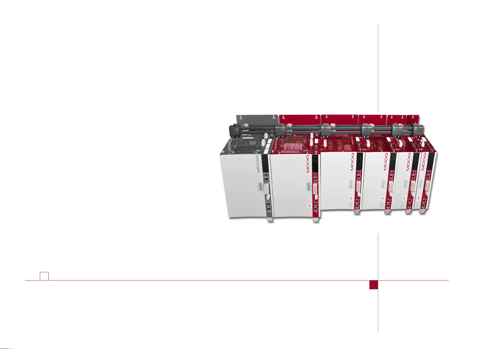
Multi-Axis System with sinusiodal regeneration
Page 2

moog
Id. no.: CA97554-001 05/2017
MSD Multi-Axis System Operation Manual DC-AC Servo Drive
MSD Servo drive energy-efficient multi-axis syste
Comprising DC-powered DC-AC Servo Drives and coordinated Power Supply Units
with sinusoidal regenerative power supply, the multi-axis system offers a high degree
of solutions expertise and flexibilit . Reduction of the wiring and shortening of the
installation times are just as easy to achieve as resource-saving, cost-conscious
operation.
2
MSD Servo Drive Operation Manual
Multi-Axis System DC-AC Servo Drive
ID no.: CA97554-001
Date: 06/2017, Rev. 2.1
Applicable as from rmware version: V2.20-01
The German version is the original of this operation manual.
Subject to technical change without notice.
The content of our documentation was complied with the greatest care and attention,
and is based on the latest information available to us.
We should nevertheless point out that this document cannot always be updated
simultaneously with the ongoing technical development of our products.
Information and specifications may be subject to change at any time. Please obtain
information on the latest version at drives-support@moog.com.
Page 3

Table of contents
1 General ..........................................................................................7
1.1 Target group ...............................................................................................................7
1.2 Prerequisites ................................................................................................................7
1.3 Reference documents ..................................................................................................7
1.4 Order code .................................................................................................................. 8
1.5 Data on manufacture ..................................................................................................9
1.6 Scope of supply ...........................................................................................................9
1.7 Pic tog ra ms .................................................................................................................. 9
1.8 Disclaimer ...................................................................................................................9
1.9 Disposal .....................................................................................................................9
1.10 Helpline/Support & Service ........................................................................................10
2 Safety ........................................................................................... 11
2.1 Overview ................................................................................................................... 11
2.2 Measures for your safety ........................................................................................... 11
2.3 General safety instructions and warnings .................................................................. 12
2.4 Intended use ............................................................................................................. 12
2.4.1 Repair ........................................................................................................13
2.5 Misuse ...................................................................................................................... 13
2.6 Responsibility ............................................................................................................ 13
2.7 Relevant laws, standards and directives applied ........................................................ 13
2.8 Declaration of conformity .........................................................................................14
2.8.1
MSD Servo Drive DC-AC Size 1 to 7..........................
..................................14
3 Mechanical installation.................................................................. 15
3.1 Notes for mechanical installation............................................................................... 15
3.2 Switch cabinet layout ................................................................................................ 16
3.2.1 Example: .................................................................................................... 17
3.3 Wall mounting (air cooling).........................................................................................18
3.4 Alignment and arrangement in the group ................................................................. 19
3.4.1 Alignment in the group .............................................................................. 19
3.4.2 Arrangement in the group ......................................................................... 20
3.5 Mounting DC-AC Servo Drive air cooling housing variant .......................................... 21
3.5.1 Dimensions and mounting clearances ........................................................22
3.6 Mounting DC-AC Servo Drive liquid cooling housing variant ..................................... 23
3.6.1 Dimensions and mounting clearances ........................................................23
3.7 Cooling circuit connection.........................................................................................26
4 Electrical installation ..................................................................... 27
4.1 Notes for installation ................................................................................................. 27
4.2 Effective EMC installation..........................................................................................28
4.2.1 Cable type ................................................................................................. 28
4.2.2 Routing of cables .......................................................................................28
4.2.3 Earthing measures ..................................................................................... 28
4.2.4 Shielding measures .................................................................................... 29
4.2.5 External components .................................................................................30
4.3 Overview of the connections .....................................................................................30
4.3.1 Layout, G393-004 (Size 1) to G393-032/G397-035 (Size 4) .......................30
4.3.2 Layout, G393-045/G397-053 (Size 5) to G393-170/G397-210 (Size 6A) .....32
4.3.3 Layout, G397-250 to G397-450 (Size 7) .....................................................34
4.4 Protective earth conductor connection......................................................................36
4.5 Electrical isolation concept ........................................................................................36
moog
Id. no.: CA97554-001 05/2017
Table of contents
MSD Multi-A xis System Operation Manual DC-AC Ser vo Drive
3
Page 4

Table of contents
moog
4.6 Connection of control supply (+24VDC) ..................................................................38
4.6.1 G393-004 (Size 1) to G393-170/G397-210 (Size 6A) ..................................39
4.6.2 G397-250.1 to G397-450 (Size 7) ..............................................................39
4.7 Connection of DC power supply ...............................................................................40
4.8 Control connections ..................................................................................................42
4.8.1 Specification of the control connections ....................................................42
4.8.2 Brake driver ................................................................................................44
4.9 Specification, USB interface ....................................................................................... 45
4.10 Specification, Ethernet interface ................................................................................45
4.11 Option1 ...................................................................................................................45
4.12 Option2 ...................................................................................................................45
4.13 Encoder connection ..................................................................................................46
4.13.1 Encoder connection for synchonous motors ..............................................46
4.13.2 Allocation of motor/encoder cable to the DC-AC Servo Drive .....................46
4.13.3 Ready made encoder cables .......................................................................46
4.13.4 Resolver connection ...................................................................................47
4.13.5 Connection for high-resolution encoders ...................................................48
4.14 Motor connection .....................................................................................................49
4.14.1 Motor connection for synchronous motors ................................................49
4.14.2 Switching in the motor cable .....................................................................52
Id. no.: CA97554-001 05/2017
5 Commissioning ............................................................................. 53
5.1 Notes for commissioning ...........................................................................................53
5.2 Initial commissioning ................................................................................................. 53
5.2.1 Switching on control supply .......................................................................54
5.2.2 Connection between PC and DC-AC Servo Drive ....................................... 54
5.2.3 Configuring parameters .............................................................................54
5.2.4 Controlling drive using Moog Dr iveA Dmini strAtor5 ..................................... 55
5.3 Serial commissioning ................................................................................................. 56
MSD Multi-A xis System Operation Manual DC-AC Ser vo Drive
5.4 Integrated control unit ..............................................................................................57
5.4.1 Function of buttons T1 and T2 ...................................................................58
5.4.2 Display ....................................................................................................... 58
5.4.3 Parameter menu (PA) .................................................................................59
5.4.4 Ethernet IP address menu (IP) ..................................................................... 59
5.4.5 Field bus address menu (Fb) .......................................................................60
4
6 Diagnostics ................................................................................... 63
6.1 Status indication on the device .................................................................................. 63
6.1.1 Device states ..............................................................................................63
6.1.2 Error indication ..........................................................................................63
6.2 Status and error indication in MoogD rive ADmin istr Ator5 ...........................................64
7 Safe Torque Off (STO) ...................................................................67
8 Operation with AC-AC Servo Drive as supply .................................69
8.1 Arrangement of the devices and components ........................................................... 69
8.1.1 Device protection ....................................................................................... 69
8.2 Switch cabinet arrangement with AC-AC Servo Drive as supply .................................74
9 Planning ....................................................................................... 75
9.1 Overview and comparison of the multi-axis systems.................................................. 75
9.2 Application examples ................................................................................................75
9.3 Operation with a Power Supply Unit .........................................................................76
9.4 Operation with AC-AC Servo Drive as supply.............................................................77
9.5 Functional comparison .............................................................................................. 78
9.6 Cost-effectiveness calculation ...................................................................................78
9.7 Dimensioning ............................................................................................................79
9.7.1 Determining the drive power required per axis ..........................................79
9.7.2 Selection of suitable gearboxes and motors ...............................................80
9.7.3 Selection of suitable DC-AC Servo Drives ...................................................80
Page 5

9.7.4 Selection of suitable Power Supply Unit ..................................................... 80
9.7.5 External components .................................................................................82
9.7.6 Selection of a suitable AC-AC Servo Drive as supply ...................................82
9.7.7 External components .................................................................................84
10 Application example .....................................................................85
10.1 Interlocking Power Supply Unit and DC-AC Servo Drives ........................................... 85
A Technical data ...............................................................................87
A.1 Current carrying capacity, MSD Servo Drives DC-AC .................................................87
A.1.1 G393-004 to G393-032 (air cooling, 400VAC) ........................................87
A.1.2 G393-004 to G393-032 (air cooling, 460VAC) ........................................88
A.1.3 G393-004 to G393-032 (air cooling, 480VAC) ........................................89
A.1.4 G393-004 to G393-032 (air cooling, 770VDC) ........................................90
A.1.5 G393-045 to G393-170 (air cooling) .......................................................... 91
A.1.6 G397-016 to G397-032 (liquid cooling, 400VAC) ....................................92
A.1.7 G397-016 to G397-032 (liquid cooling, 460VAC) ....................................93
A.1.8 G397-016 to G397-032 (liquid cooling, 480VAC) ....................................93
A.1.9 G397-016 to G397-032 (liquid cooling, 770VDC) ....................................94
A.1.10 G397-045 to G397-170 (liquid cooling) ......................................................94
A.1.11 G397-250 to G397-450 (liquid cooling) .....................................................95
A.2 Technical data, MSD Servo Drive DC-AC ....................................................................96
A.2.1 G393-004 to G393- 020 / G397-020 to G397-025 .....................................96
A.2.2 G393-024 to G393-072 / G397-026 to G397-084 ..................................... 96
A.2.3 G393-090 to G393-170 / G397-110 to G397-210 .......................................97
A.2.4 G397-250 to G397-450 .............................................................................97
A.3 Power connections ....................................................................................................98
A.4 Current required for the control supply .....................................................................99
A.5 Pre-assembled DC link connections .........................................................................100
A.5.1 DC coupling, Power Supply Unit and DC-AC Servo Drive ......................... 101
A.5.2 DC coupling, DC-AC Servo Drive and DC-AC Servo Drive ......................... 101
A.5.3 DC coupling, AC-AC Servo Drive and DC-AC Servo Drive ......................... 102
A.6 Ambient conditions .................................................................................................104
A.7 Hydrological data for the liquid cooling ................................................................... 105
A.8 Dynamic temperature monitoring ...........................................................................106
A.9 UL certification (Size 1 to Size 7) .............................................................................10 6
Glossary ............................................................................................. 107
moog
Id. no.: CA97554-001 05/2017
Table of contents
MSD Multi-A xis System Operation Manual DC-AC Ser vo Drive
5
Page 6

Table of contents
moog
Id. no.: CA97554-001 05/2017
MSD Multi-A xis System Operation Manual DC-AC Ser vo Drive
6
Page 7
1 General
1.3 Reference documents
The product DVD from Moog contains the complete documentation for the related
product series. The documentation for a product series includes the Operation Manual
(hardware description), Device Help (software description) as well as further
User
Manuals (e.g. field bus description) and Specifications. They are available in the formats
PDF, HTML or chm.
1.1 Target group
Dear user,
the documentation forms part of the device and contains important information on
operation and service. It is aimed at all persons who undertake mounting, installation,
commissioning and servicing work on the product.
1.2 Prerequisites
Prerequisites for the usage of devices from Moog GmbH:
• The documentation on the devices is to be stored so it legible, accessible at all
times and for the entire life of the product.
• Read and ensure you understand the documentation on your device.
•
Qualification: to p event injury or damage, personnel may only work on the
device if they have electrical engineering qualifications
• Knowledge required:
− National health and safety regulations (e.g. VSize 4 in Germany)
− Mounting, installation, commissioning and operation of the device
Work in other areas, for example transport, storage and disposal is only allowed to be
undertaken by trained personnel.
NOTE
This operation manual only applies to the DC-AC Servo Drive for the
MSD Multi-Axis System (referred to in the following as the DC-AC Servo Drive).
Document Contents
MSD Single-Axis
Servo Drive CompactOperation Manual
MSD Servo Drive
AC-AC Servo Drive
Single-Axis System Operation Manual
MSD Servo Drive
DC-AC Servo Drive
Multi-Axis SystemOperation Manual
MSD Power Supply Unit
Multi-Axis SystemOperation Manual
MSD Servo Drive
Sercos II User Manual
MSD Servo Drive
Sercos III User Manual
MSD Servo Drive Field bus
systems CANopen/EtherCAT User Manual
MSD Servo Drive
Field bus systems
Probus/Pronet
User Manual
Modular Multi-Axis Servo
Drive System - MSD Ordering Catalog
MSD Servo Drive - Device
Help
Program help
DriveADminsitrAtor 5
Moog
PC user software
Safety, mechanical installation, electrical installation,
commissioning, diagnostics, specications, certication and
applicable standards, technical data
Safety, mechanical installation, electrical installation,
commissioning, diagnostics, specications, certication and
applicable standards, technical data
Safety, mechanical installation, electrical installation, commissioning,
diagnostics, STO, operation with AC-AC Servo Drive as supply,
planning, application example, specications, certication and
applicable standards, technical data
Safety, mechanical installation, electrical installation, commissioning,
diagnostics, specication, certication and applicable standards,
technical data
Safety, commissioning, communication phases, parameter interface,
error, warning and status messages, operation modes, weighting,
referencing, touchprobe, parameter lists
Safety, installation and connection, commissioning and conguration,
parameterisation, data transmission, scaling and weighting,
functionality, error message and diagnostics, parameter lists
Safety, commissioning, data transmission, operation modes,
referencing, parameters, technical data
Description and conguration of the parameters for the MSD Servo
Drive on the PROFIBUS/PROFINET eld bus system
Information, notes on ordering, specications and
technical data on:
MSD Single-Axis Servo Drive Compact, MSD Single-Axis System,
MSD Multi-Axis System, safety technology, communication,
technology, function packages, accessories and motors
Description of the software functionality MSD Servo Drive,
rmware versions:
- MSD Single-Axis Servo Drive Compact from V1.30-xx
- MSD Single-Axis System from V3.25-xx
- MSD Multi-Axis System from V3.25-xx
Context-sensitive help for Moog DriveADministrAtor version 5.x
graphic PC user software for initial commissioning and serial
commissioning, operation, diagnostics and project management
ID no.
Format
CA97555-001
PDF
CA65642-001
PDF
CA97554-001
PDF
CA97556-001
PDF
CA65648-001
PDF
CA97557-001
PDF
CA65647-001
CA65645-001
PDF
CDL 29950-en
PDF
CB40859-001
PDF and
HTML
CB19692-001
moog
Id. no.: CA97554-001 05/2017
1 General
MSD Multi-Axis System Operation Manual DC-AC Servo Drive
7
Page 8
1 General
moog
Id. no.: CA97554-001 05/2017
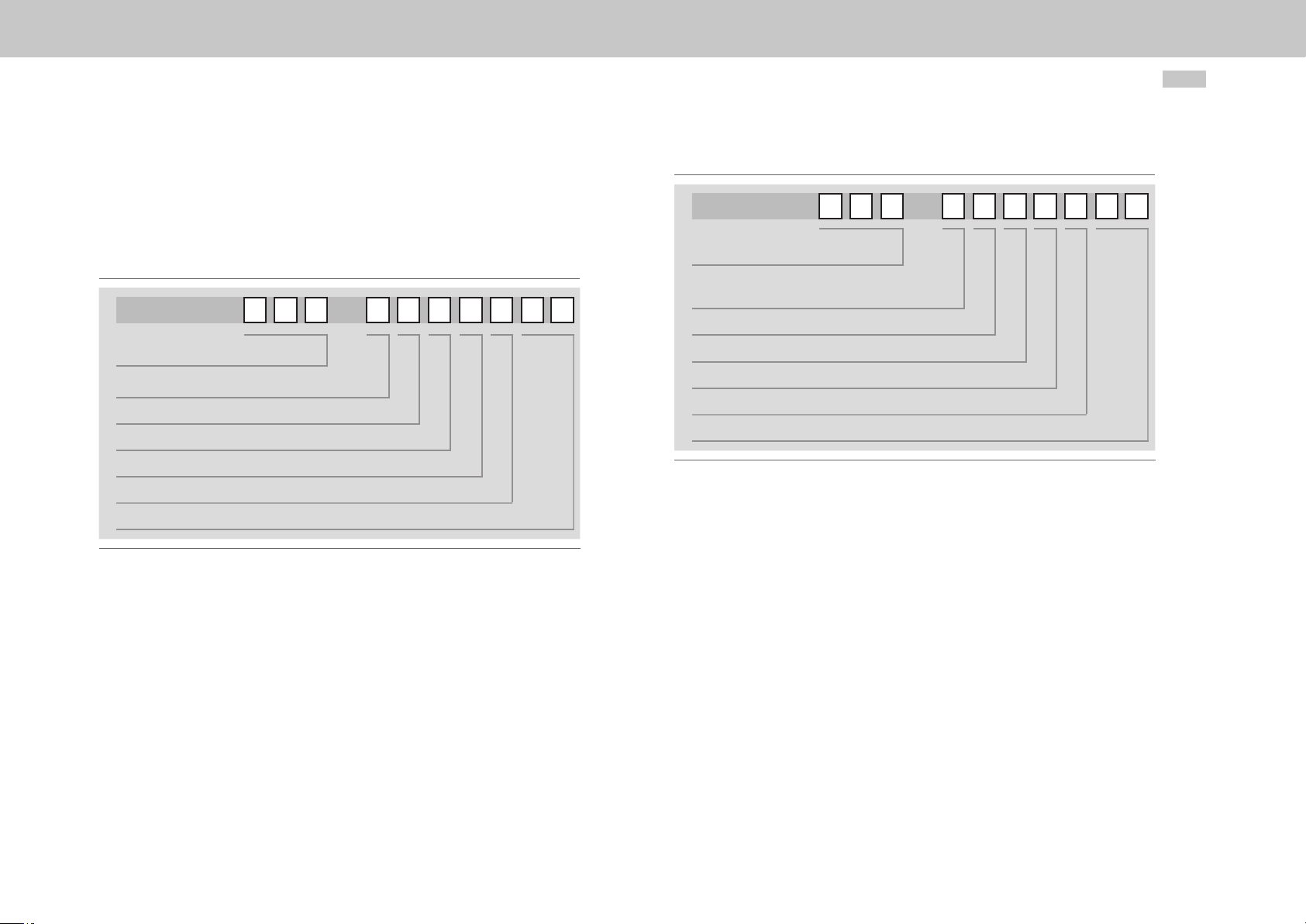
1.4 Order code
The MSDMulti-Axis System has the article designation G393-xxx-xxxxxxx and
G397-xxx-xxxxxxx. This provides information on the related variant of the
MSDServoDrive supplied. The signicance of the individual characters of the article
designation is given in the following order code.
G393 - - -
Rated current
Option 1 (Communication)
Option 2 (Technology)
Option 3 (Safety)
Option 4 (Function package)
Modificatio
Variants
MSD Multi-Axis System Operation Manual DC-AC Servo Drive
G397 - - -
Rated current
Option 1 (Communication)
Option 2 (Technology)
Option 3 (Safety)
Option 4 (Function package)
Modificatio
Variants
Figure 1.2 Order code MSD Servo Drive DC-AC (liquid-cooled)
8
Figure 1.1 Order code MSD Servo Drive DC-AC (air-cooled)
Page 9
1.5 Data on manufacture
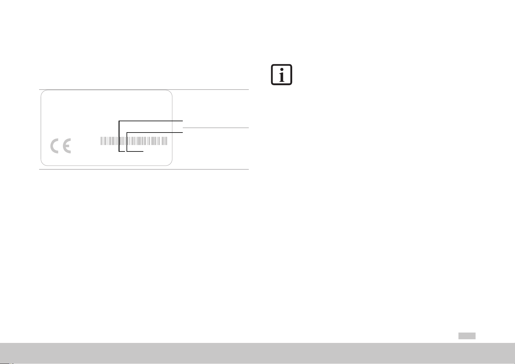
1.7 Pictograms
On rating plates for the servo drives you will find the serial number, from which you can
identify the date of manufacture based on the following key. For the location of the rating
plate on the MSDServoDrive refer to the layouts in chapter4.3, page30
sizes Size 1 to 7.
MOOG
D-71034 Böblingen
www .moog.com/industrial
Made in Germany
Model:: G393-030-000-002
S/N:D116605 Rev. A
In: 230 V AC 3ph, 50/60 Hz
4,0 A
0-230 V AC 3ph, 0-400 Hz
Out:
3,0 A
Year of production
Week of production
for the related
ID : JJWWxxxxx
Figure 1.3 DC-AC Servo Drive hardware rating plate
1.6 Scope of supply
The scope of supply includes:
MSDServoDrive DC-AC
•
Terminal kit for control and power terminals
•
(depending on device power and variant)
•
Set of grommets (on devices with liquid cooling)
• Pre-assembled DC link connections
• Product DVD with booklet
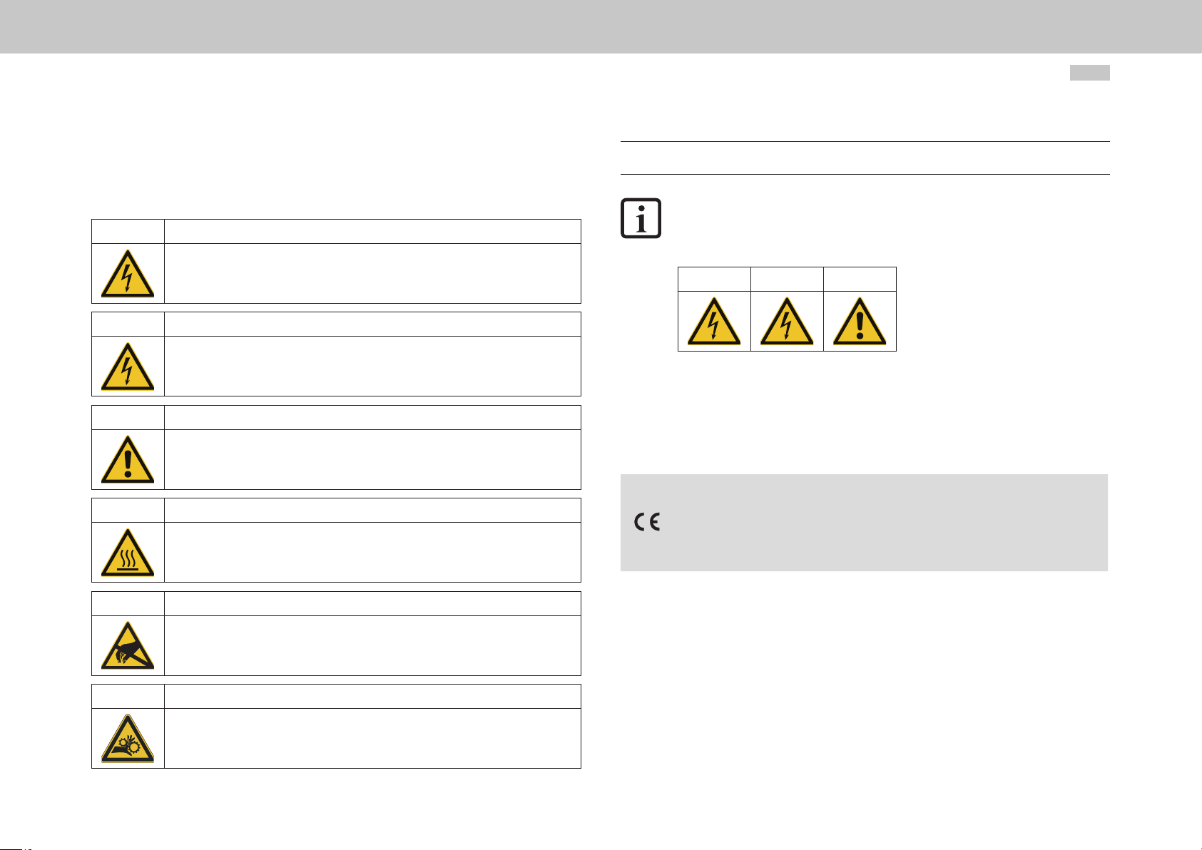
The pictograms used in this operation manual signify the following for the user:
NOTE
Useful information or reference to other documents.
1.
(digit)
You will find the pictograms used in this operation manual for "safety instructions and
warnings" in chapter 2 Safety.
ACTION TO BE TAKEN
Processing step undertaken by the user or the system.
1.8 Disclaimer
Following the documentation on the devices from Moog is a prerequisite:
•
For safe operation.
•
To achieve stated performance features and product characteristics.
Moog does not accept any liability for injuries, damage or financial losses that esult from
the failure to follow the documentation.
1.9 Disposal
Follow the applicable national regulations! If necessary, dispose of individual parts,
depending on their characteristics and existing national regulations, e.g. as:
• Electrical waste
• Plastic
• Metal
Or engage a certified disposal organisation with scrappin
moog
Id. no.: CA97554-001 05/2017
1 General
MSD Multi-Axis System Operation Manual DC-AC Servo Drive
9
Page 10

1 General
moog
Id. no.: CA97554-001 05/2017
1.10 Helpline/Support & Service
Our Helpline will help you with fast, specific assistance if you have any technical queries
relating to project planning or commissioning your device.
Address: Moog GmbH
Hanns-Klemm Straße 28
D-71034 Böblingen
Phone: +497031622-0
Fax: +497031622-100
E-mail: drives.support@moog.com
If you need service assistance, the Moog specialists will be pleased to be of assistance.
Service - Please contact us:
Phone: +497031622-0
E-mail: info.gemany@moog.com
MSD Multi-Axis System Operation Manual DC-AC Servo Drive
10
Page 11

2 Safety
2.1 Overview
Our devices are state-of-the-art and comply with recognised safety regulations,
nevertheless hazards can arise. In this chapter:
• We provide information on residual risks and hazards that can emanate from
our devices on usage as intended.
• We warn about the foreseeable misuse of our devices.
•
We refer to the necessary care and measures to be taken to prevent risks.
2.2 Measures for your safety
NOTE
Only install and place in operation your device taking into account the
documentation for the related device family!
Our devices are quick and safe to operate. For your own safety and for the safe
functioning of your device, please be sure to observe the following points:
3.
4.
5.
Protection against magnetic and/or electromagnetic fields during
installation and operation.
Persons tted with heart pacemakers, metallic implants and hearing aids etc. must not be allowed
access to the following areas:
• Areas in the immediate vicinity of electrical equipment!
• Areas in which electronics components and servo drives are installed, repaired and operated!
• Areas where motors are installed, repaired and operated!
Motors with permanent magnets pose particular hazards.
During installation observe the following:
• Comply with connection conditions and technical data as per the documentation and the rating
plate!
• Comply with standards and directives on electrical installation, such as cable cross-section,
shielding, etc.!
• Do not touch electronic components and contacts!
Electrostatic discharge can harm people and destroy components!
• Take protection measures and use protective devices as per the applicable regulations
(e.g. IEC/EN60204 or IEC/EN61800-5-1)!
• Take "device earthing" protection measure!
Ambient conditions
•
Follow the instructions on the transport, storage and correct operation of the devices stated in
the Operation Manual in "A Appendix".
1.
2.
moog
Follow safety instructions for the devices:
Follow all safety instructions and warnings in the entire documentation related to the device series.
Electric drives are dangerous:
• Due to electrical voltages up to 480V AC and up to 800V DC
• Even 10min. after switching off the mains supply, dangerously high voltages of ≥50V may
still be present (capacitor charge). So check that electrical power is not present! See also the
warning label on the front panel on the device.
• Rotating parts
• Automatically starting drives.
• Hot components and surfaces
Id. no.: CA97554-001 05/2017
2 Safety
MSD Multi-Axis System Operation Manual DC-AC Servo Drive
11
Page 12
2 Safety
moog
Id. no.: CA97554-001 05/2017
2.3 General safety instructions and warnings
Hazards may emanate from our devices. For this reason it is imperative you follow the
safety instructions and warnings in this document.
DANGER! Risk of injury due to electrical power!
• Carelessness will result in serious injuries or death.
Follow safety instructions and warnings in this document and on the device.
WARNING! Risk of injury due to electrical power!
• Carelessness may result in serious injuries or death.
Follow safety instructions and warnings in this document and on the device.
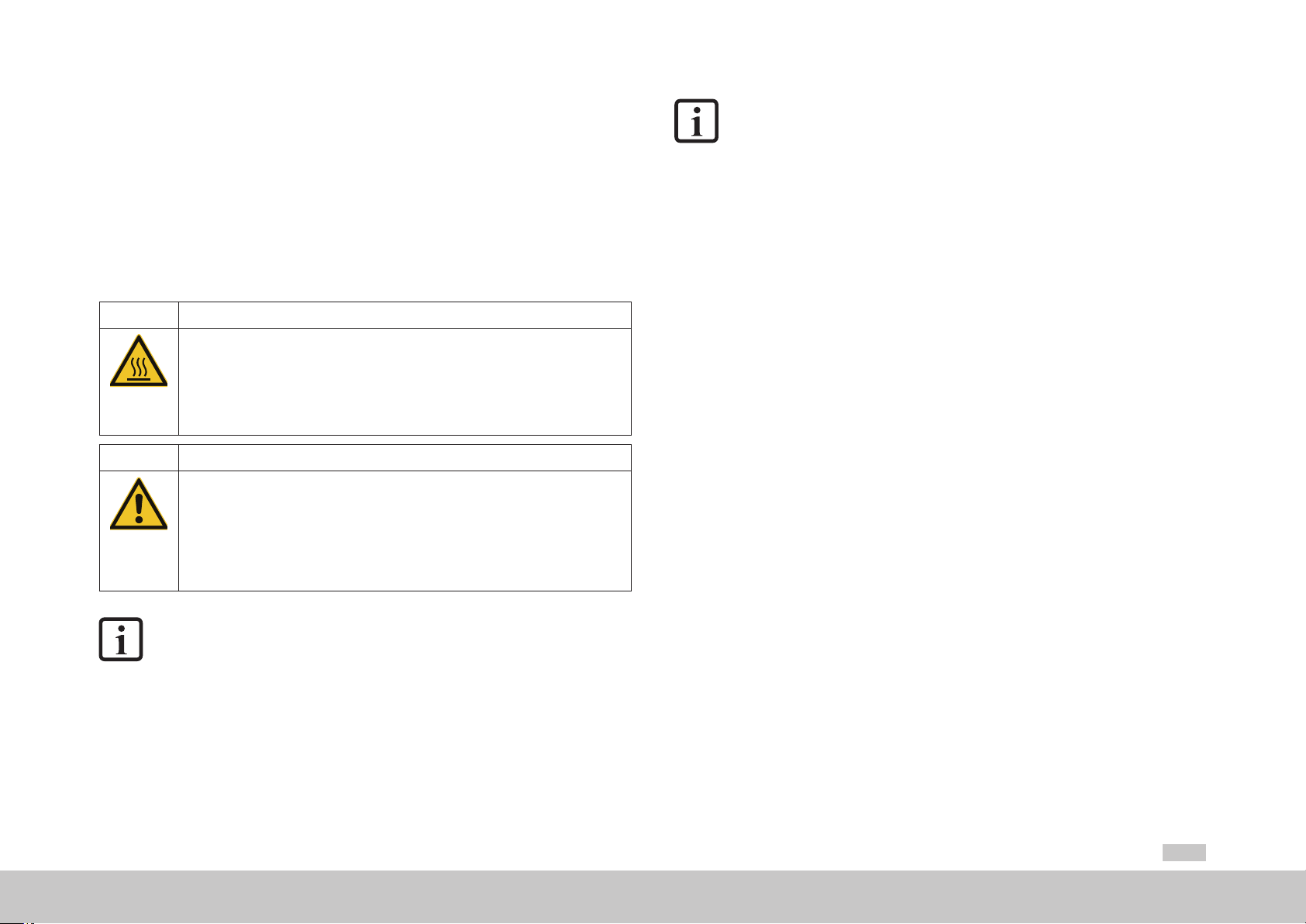
CAUTION! Risk of injury or damage to the device due to incorrect operation!
• Carelessness may result in minor injuries or
damage.
Follow safety instructions and warnings in this document and on the device.
WARNING! Risk of injury due to hot surfaces and components!
• Carelessness may result in serious burns.
Electronic components may become hot during operation!
Follow safety instructions and warnings in this document and on the device!
MSD Multi-Axis System Operation Manual DC-AC Servo Drive
Pay attention to special safety instructions and warnings that are given here in the document before a
specic action and that warn the user about a specic hazard!
NOTE:
The pictograms may also be used on their own with the signal word, e.g.
in the connection diagrams, however they have the same function as in the
complete warning.
DANGER WARNING CAUTION
12
2.4 Intended use
Our devices are components intended for stationary electrical systems and machines in
the industrial and commercial sector.
The devices in the product range MSD Multi-Axis System conform to the
Machinery Directive 2006/42/EC (Size 1 to Size 6A)
Low Voltage Directive 2014/35/EU (Size 7)
Tested and certied according to applicable standards (see declaration of conformity in
chapter 2.8).
Caution! Damage due to electrostatic discharge!
• Electrostatic discharge can destroy components.
Do not touch electronic components and contacts!
Follow safety instructions and warnings in this document and on the device!
DANGER! Risk of injury due to rotating parts on the motor!
• Carelessness will result in serious injuries or death.
Follow safety instructions and warnings in this document.
When installed in machines it is prohibited to start-up intended operation until it has
been ascertained that the completed machine fully complies with the provisions of the
Machinery Directive (2006/42/EC); compliance with IEC/EN60204 is mandatory.
Starting up intended operation is only permitted on compliance with the EMC Directive
2014/30/EU.
The devices fulfil the demands of the harmonised p oduct standard
You will find information on the installation of your device in chapter “3 Mechanical
installation”.
IEC/EN 61800-5-1.
Page 13

2.4.1 Repair
Only have repairs undertaken by authorised repair shops. Unauthorised opening and
incorrect intervention could lead to death, physical injury or material damage. The
warranty provided by Moog will be rendered void.
2.5 Misuse
Our devices are:
• Not intended for installation in vehicles. Deployment of the device in mobile
equipment is classed as non-standard ambient conditions, and is permissible
only by special agreement.
• Not intended for installation in environments with harmful oils, acids, gases,
vapours, dusts, radiation etc.
Not approved for usage in special applications (e.g. in potentially explosive
•
atmospheres or areas in which there is a risk of fire).
• Not approved for usage outside a switch cabinet
• Not approved for the generation of high-frequency onboard networks for which
the device is not designed
2.6 Responsibility
Pay attention to the topic of “Electrical equipment of machines” in EN60204-1:2006
“Safety of machinery”. The safety requirements on electrical machines defined the e are
intended to protect personnel and machinery or systems.
The emergency stop function (as per IEC/EN60204) shuts down the supply of power to
a machine, which results in the drives coasting down in an uncontrolled manner. To avert
hazards, check whether it is appropriate:
− To keep individual drives in operation
− To initiate specific safety p ocedures
− To incorporate a Safe Torque Off function (Safe Torque Off: movement stop
by "switching off the electrical supply" - STO)
2.7 Relevant laws, standards and directives applied
For information on the laws, standards and directives applied by Moog, refer to the
declaration of conformity.
NOTE:
Depending on the specific application for the devices, other laws, standa ds
and directives with provisions on "Safety" may apply. If necessary, contact the
machine or system manufacturer.
Electronic devices are not fail-safe. The installer and/or operator of a complete machine
or system is responsible for ensuring:
• That the drive is rendered safe if the device fails
• The safety of personnel and machinery
• The complete machine is in correct working order
•
For the risk assessment on the complete machine or system according to
EN ISO 12100 (formerly EN ISO 14121) and EN ISO 13849-1 (formerly
DIN EN 954-1)
moog
Id. no.: CA97554-001 05/2017
2 Safety
MSD Multi-Axis System Operation Manual DC-AC Servo Drive
13
Page 14
2 Safety
moog
Id. no.: CA97554-001 05/2017
2.8 Declaration of conformity
2.8.1 MSD Servo Drive DC-AC Size 1 to 7
MSD Multi-Axis System Operation Manual DC-AC Servo Drive
14
Page 15
3 Mechanical installation
The device is designed only for installation in a stationary switch cabinet. The switch
cabinet must as a minimum provide IP4x protection. According to ENISO13849-2 the
switch cabinet must have IP54 protection or higher when using the safety function STO
(Safe Torque Off).
3.1 Notes for mechanical installation
WARNING! Risk of injury due to hot surfaces on the device (heat sink)!
• Carelessness may result in serious burns.
The device and especially the heat sink heat up signicantly during operation and can reach
temperatures of up to +100°C (+212°F). Prior to starting work, make sure the device has
cooled down.
On touching there is a risk of burns to the skin. For this reason provide protection against
touching.
During mounting maintain an appropriate distance to neighbouring assemblies.
CAUTION! Damage to the device due to incorrect installation conditions!
The device may suffer irreparable damage.
For this reason
• Moisture must not be allowed to enter the device
• There must not be any aggressive or conductive substances in the ambient air
• Foreign bodies such as drilling chips, screws, washers etc. must not be allowed to fall into
the device
• The ventilation openings must not covered
NOTE:
It is imperative the operation manuals for the DC-AC Servo Drive and the
Power Supply Unit or the supplying AC-AC Servo Drive are followed during
installation of a MSDMulti-Axis System.
The following basic guidelines apply to the arrangement and installation of the Power
Supply Unit or the DC-AC Servo Drive:
• The backing plate must be well grounded.
• To attain the best result for effective EMC installation you should use a
chromated or galvanised backing plate. If backing plates are varnished, remove
the coating from the contact area! The devices Size 1 to Size 4 and Size 7 have
a rear wall made of aluminium. The devices Size 5 and Size 6A have a rear wall
made of aluminised/galvanised sheet steel.
• Maximum degree pollution degree 2 according to IEC/EN 60664-1. You will find
further information on ambient conditions in Table A.29 in the appendix.
• Cooling air must be able to flow th ough the device without restriction.
•
On installation in switch cabinets with convection, i.e. heat loss is dissipated to
the outside via the switch cabinet walls, always fit an inte nal air circulation fan.
If you require further detailed information on installation, please contact the
MoogHelpline (see chapter1.10, page10).
NOTE:
The DC-AC Servo Drives must not be installed in areas where they would be
permanently exposed to vibration.
You will find further information in Table A.27 in the appendix.
moog
Id. no.: CA97554-001 05/2017
3 Mechanical installation
MSD Multi-Axis System Operation Manual DC-AC Servo Drive
15
Page 16

3 Mechanical installation
moog
Id. no.: CA97554-001 05/2017
3.2 Switch cabinet layout
The positioning of the components in the switch cabinet has a significant e fect on the
trouble-free system and machine function. You should take into account the following
points in your planning:
•
Evaluate the assemblies used in relation to EMC.
•
Divide the switch cabinet into zones with different power and interference levels.
•
For devices susceptible to interference, maintain a distance of at least 200mm
(7.87 in) from the following components:
− DC-AC Servo Drive
− Input and output chokes, transformers
− Mains, motor, DC power supply and braking resistor cables (even if shielded)
− Relay and contactors (even if interference-suppressed)
•
For small distances use separators for shielding; fasten the separators directly
and conductively to the backing plate.
•
If a motor contactor or motor choke is used, the component should be directly
positioned directly at the DC-AC Servo Drive.
•
Do not use fluo escent lamps in switch cabinets, as they emit high-frequency
interference.
•
Fit contactors, relays, solenoid valves, switched inductors and capacitors with
suppressors.
•
The mains filter must be mounted on the backing plate as close as possible to
the feed point and with large surface area contact. The backing plate must be
connected to the central earthing point with a low-impedance connection. No
unfilte ed cables are allowed to be laid on the mains input side of the filter so
that no interference can be coupled into the cables.
MSD Multi-Axis System Operation Manual DC-AC Servo Drive
16
Page 17
3.2.1 Example:
< 200 mm
< 20
12 9
1) Mains cable
2) Main switch
3) Fuses
4) Mains lter 1)
11
PWR
LOCK
CF
14
5) Circuit breaker
6) Mains contactor
7) Input choke with capacitor connected
8) Step-up choke
Power
COM
Data
Status
10
Reset
RJ-45/Line
RS 232
10
10
10
9) MSD Power Supply Unit
10) MSD Servo Drive DC-AC
11) DC power supply via DC link cable
12) Braking resistor
13) Motor cables
14) Controller 2)
3
0
5
1
OFF
ON
0
2
6
8
1
1) Cables without interference suppression must be laid at a distance of at least 200 mm (7.87 in) from the mains input side of the lter so that no interference can be coupled into the cables.
2) Arrange the controller separated from the power area to prevent EMC coupling mechanisms. Control cables, signal cables and cable shields have been omitted for clarity
7
4
13
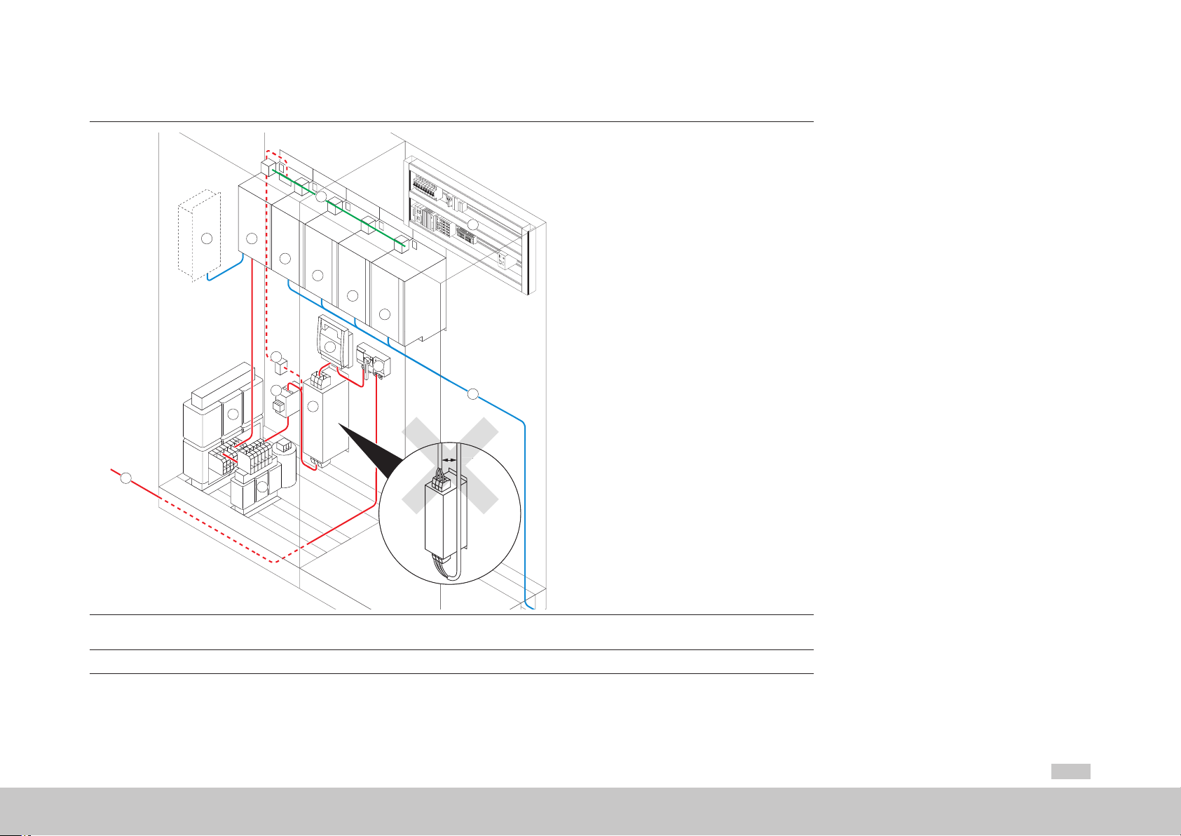
Figure 3.1 Example: arrangement in the switch cabinet
moog
Id. no.: CA97554-001 05/2017
MSD Multi-Axis System Operation Manual DC-AC Servo Drive
17
3 Mechanical installation
Page 18
3 Mechanical installation
moog
Id. no.: CA97554-001 05/2017
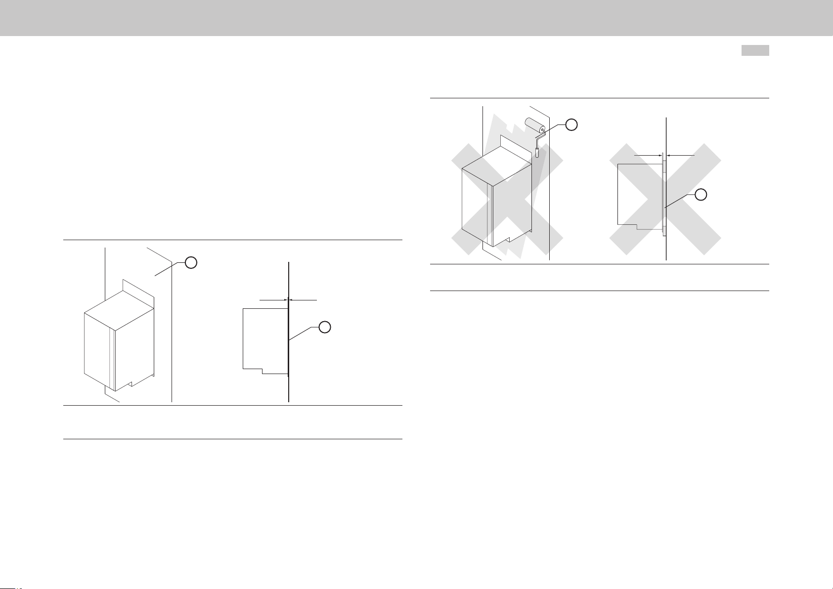
3.3 Wall mounting (air cooling)
•
Use bare metal backing plates.
•
The rear of the DC-AC Servo Drive must have good contact to the switch
cabinet ground. The contact area must be bare metal to establish a good
ground connection to the switch cabinet ground. There must not be an air gap
between the rear wall of the DC-AC Servo Drive and the rear wall of the switch
cabinet.
•
The bases of the chokes must have good contact to the switch cabinet ground.
The contact area must be bare metal to establish a good ground connection to
the switch cabinet ground.
1
= 0 mm
MSD Multi-Axis System Operation Manual DC-AC Servo Drive
1
> 0 mm
2
1) Paint
2) Air gap
Figure 3.3 INCORRECT mounting of DC-AC Servo Drive
2
18
1) Bare metal backing plate
2) Large area contact
Figure 3.2 CORRECT mounting of DC-AC Servo Drive
Page 19
18.5 mm (0.73 in)
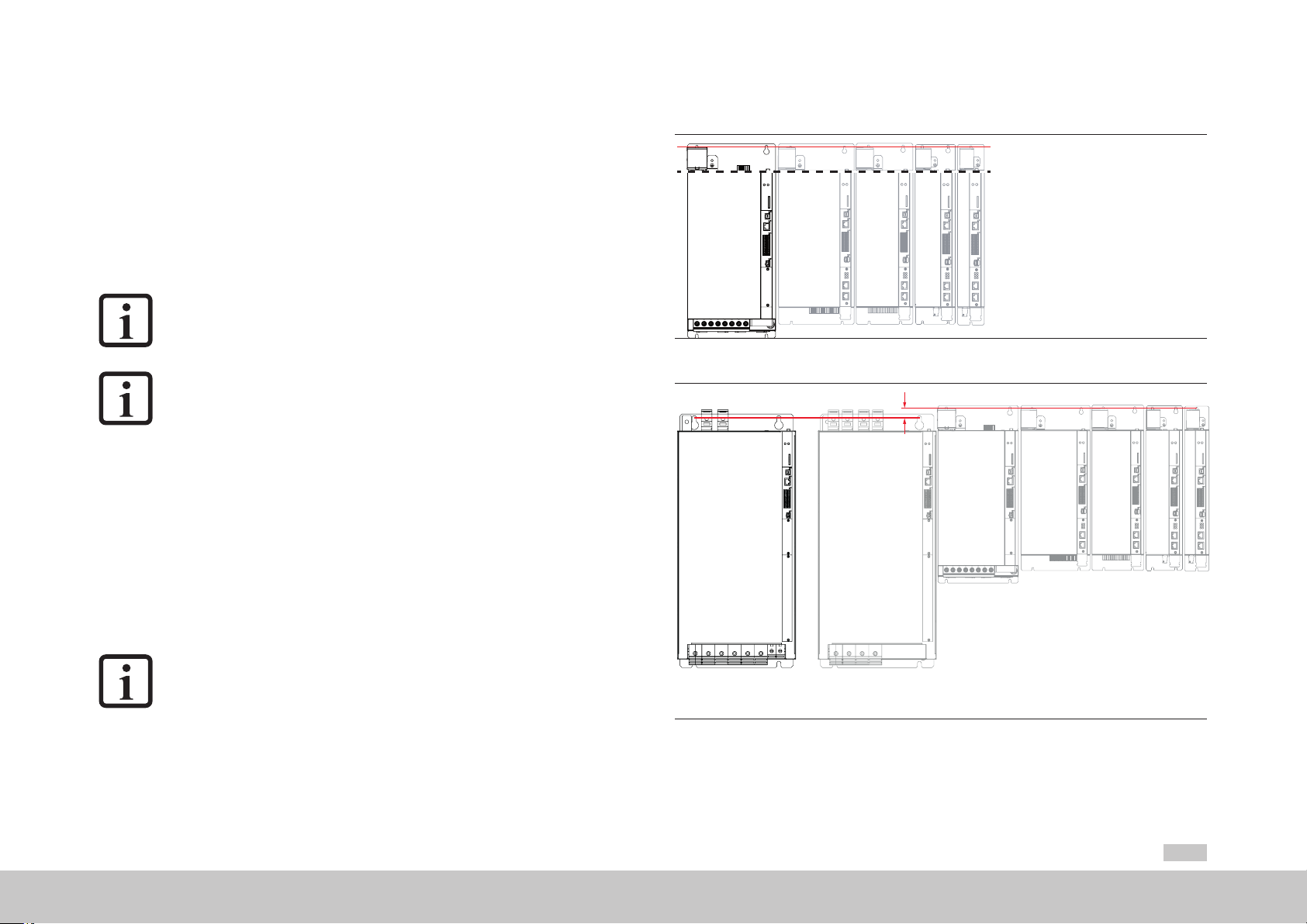
3.4 Alignment and arrangement in the group
•
Devices with different housing variants, such as air cooling and liquid cooling,
can be mounted side-by-side in any combination.
•
Devices with the liquid cooling housing variant have a spacer on the rear in
place of the heat sink. As a consequence it is possible to connect devices with
the air cooling housing variant using pre-assembled DC link cables without
additional compensation measures in relation to the device depth.
• The distance between the devices in a row is defined by the pre-assembled
connection cables supplied and is 2mm (0.08in).
NOTE
Devices of Size 6A in the air cooling housing variant are an exception. The
mounting distance between two air-cooled devices of Size 6A is 40mm
(1.57in) (see Figure 3.5).
NOTE
Only use the DC link connections supplied for the electrical coupling of the
devices. If extending the DC link coupling is unavoidable, it is imperative you
pay attention to the requirements in chapterA.5, page103. On the usage of
connection cables that do not meet the requirements, Moog does not provide
any guarantee for stable, safe operation.
•
The DC-AC Servo Drives are allowed to be arranged to the left and/or right
of a Power Supply Unit. On side by side mounting devices with different drive
powers you should arrange the devices in descending order by power rating
(e.g., viewed from the left, Size 4-Size3-Size2-Size1). This arrangement will
minimise the thermal interaction. The Power Supply Unit must always be fitted
beside the DC-AC Servo Drive with the highest power.
On side by side mounting other devices to the multi-axis system, attention is to
be paid to ensuring there is no thermal interaction between the devices.
•
Align the devices along the top edge (dotted line) to ensure trouble-free wiring.
NOTE
Between the upper fastening screws for devices of Size 1 to Size 5 there is a
vertical offset of 18.5mm (0.73in) compared to devices of Size 6A
(see Figure 3.5).
3.4.1 Alignment in the group
MSD
Power Supply Unit
Size 5
MSD Servo Drive DC-AC Size 1
MSD Servo Drive DC-AC Size 4
Figure 3.4 Alignment of DC-AC Servo Drives in relation to Power Supply Unit Size 5 (example)
MSD Power Supply Unit
Size 6A
Wall mounting
Figure 3.5 Alignment of DC-AC Servo Drives in relation to Power Supply Unit Size 6A (example)
MSD Servo Drive DC -AC
MSD Servo Drive DC-AC Size 3
Size 6A
Wall mounting
MSD Servo Drive DC-AC Size 2
MSD Servo Drive DC-AC Size 5
MSD Servo Drive DC-AC Size 4
MSD Servo Drive DC-AC Size 2
MSD Servo Drive DC-AC Size 3
MSD Servo Drive DC-AC Size 1
moog
Id. no.: CA97554-001 05/2017
3 Mechanical installation
MSD Multi-Axis System Operation Manual DC-AC Servo Drive
19
Page 20
MSD Servo Drive DC-AC Size 1
MSD Servo Drive DC-AC Size 2
MSD Servo Drive DC-AC Size 3
MSD Servo Drive DC-AC Size 4
MSD Servo Drive DC-AC Size 5
18.5 mm (0.73 in)
MSD Servo Drive DC -AC
Size 6A
with liquid cooling
MSD Power Supply Unit
Size 6A
with liquid cooling
3 Mechanical installation
moog
Id. no.: CA97554-001 05/2017
Figure 3.6 Alignment of DC-AC Servo Drives in relation to Power Supply Unit Size 7 (example)
MSD Multi-Axis System Operation Manual DC-AC Servo Drive
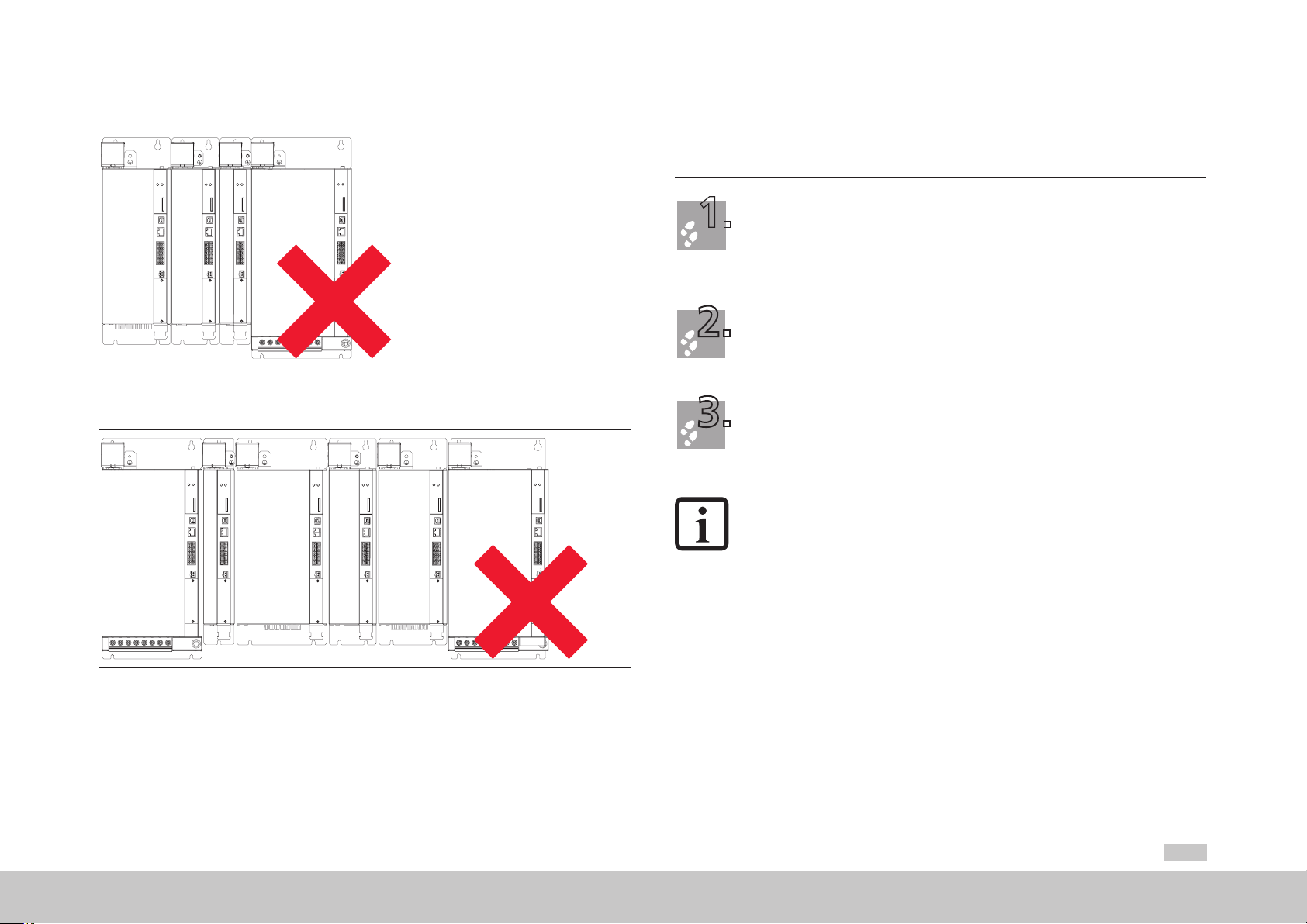
3.4.2 Arrangement in the group
Permissible arrangements
G396
Figure 3.7 Example permissible arrangement: side by side mounting DC-AC Servo Drive
of the same size on one side of the Power Supply Unit
20
G396
Figure 3.8 Example permissible arrangement: side by side mounting DC-AC Servo Drive
of the same size or reducing size on both sides of the Power Supply Unit
Page 21
1.
2.
3.
Impermissible arrangements
G396
3.5 Mounting DC-AC Servo Drive air cooling housing variant
Arrange the devices starting from the Power Supply Unit to the right or/and left sorted in descending
order by power rating to minimise the thermal effects.
Align all devices in a line along the top edge of the devices so that the DC link coupling can be made
using the pre-assembled cables. Between the upper fastening screws for devices of Size 1 to Size 5
there is a vertical offset of 18.5mm (0.73in) compared to devices of Size 6A (see Figure 3.5). For
information on the mounting clearances see Table 3.1.
Mark out the position of the tapped holes on the backing plate.
Drill holes in the backing plate and cut a thread for each xing screw in the backing plate.
Pay attention to the bending radius of the connection cables!
For hole spacing and dimensional drawings see Table 3.1, Figure 3.11 and Figure 3.12.
Figure 3.9 Example of an impermissible arrangement: side by side mounting DC-AC Servo Drive
of increasing size
G396
Figure 3.10 Example of an impermissible arrangement: side by side mounting DC-AC Servo Drive
of increasing and reducing sizes
Mount the DC-AC Servo Drives vertically and side by side mounted in a row on the backing plate.
The contact area must be bare metal. Use the pre-assembled DC link cables supplied for the DC
power supply.
Continue with the electrical installation in chapter4, page27.
NOTE:
The minimum distance specified in the table applies for devices of the same
power. On side by side mounting devices with differ
should arrange the devices in descending order by power rating (e.g., viewed
from the left, Size 4-Size 3-Size 2-Size 1). This arrangement will minimise the
thermal interaction. The Power Supply Unit must always be fitted beside the
DC-ACServo Drive with the highest power.
On side by side mounting other devices to the multi-axis system, attention is
to be paid to ensuring there is no thermal interaction between the devices.
ent drive powers you
moog
Id. no.: CA97554-001 05/2017
3 Mechanical installation
MSD Multi-Axis System Operation Manual DC-AC Servo Drive
21
Page 22
3 Mechanical installation
moog
Id. no.: CA97554-001 05/2017
3.5.1 Dimensions and mounting clearances
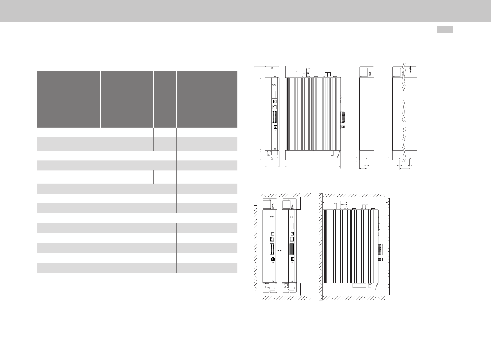
Size Size 1 Size 2 Size 3 Size 4 Size 5 Size 6A
Device
G393-004
G393-006
Weight kg (lb) 3.4 (7.5) 4.9 (10.8) 6.5 (14.3) 7.5 (16.5) 13 (28.7) 32 (70.6)
B (width) 58.5 (2.30) 90 (3.54) 130 (5.12)
1)
H (height)
1)
D (depth)
A 29.25 (1.15) 50 (1.97) 80 (3.15)
C 382 (15.04) 406.5 (16) 581 (22.87)
C1 5 (0.2) 6 (0.24) 10 (0.39)
D (Ø) 4.8 (0.19) 5.6 (0.22) 9.5 (0.37)
E Direct side by side mounting, maximum 2 (0.08) 40 (1.57)
3)
F
3)
G
≥100 (3.94) ≥150 (5.91) ≥180 (7.09)
G393-008
G393-012
G393-016
G393-020
G393-024
171
(6.73)
G393-032
G393-045
G393-060
G393-072
190 (7.48) 280 (11.02)
G393-090
295 (11.61) 345 (13.58) 540 (21.26)
224 (8.82) 240 (9.45) 322 (12.68)
120
(4.72)
150 (5.91) 200 (7.87)
≥270 (10.63) ≥300 (11.81) ≥500 (19.69)
G393-110
G393-143
G393-170
2)
MSD Multi-Axis System Operation Manual DC-AC Servo Drive
Size 1
H2
TB D
C1 C1
Figure 3.11 Dimensional drawing, air cooling housing variant
F
G
Size 2 ... Size 6
CCH1 H
DD
22
AA
H1 392 (15.43) 418.5 (16.48) 600 (23.62)
H2 38.5 (1.52) 15 (0.59) 20 (0.79)
Screws 2 x M4 4 x M4 4 x M5 4 x M8
1) Without terminals/connectors 3) The bend radius of the connection cables must be taken into account
2) Mounting distance Size 6A to other Size 6A All dimensions in mm (in)
Table 3.1 Dimensions and mounting clearances, air cooling housing variant
E
F
Figure 3.12 Mounting distances, air cooling housing variant
Page 23
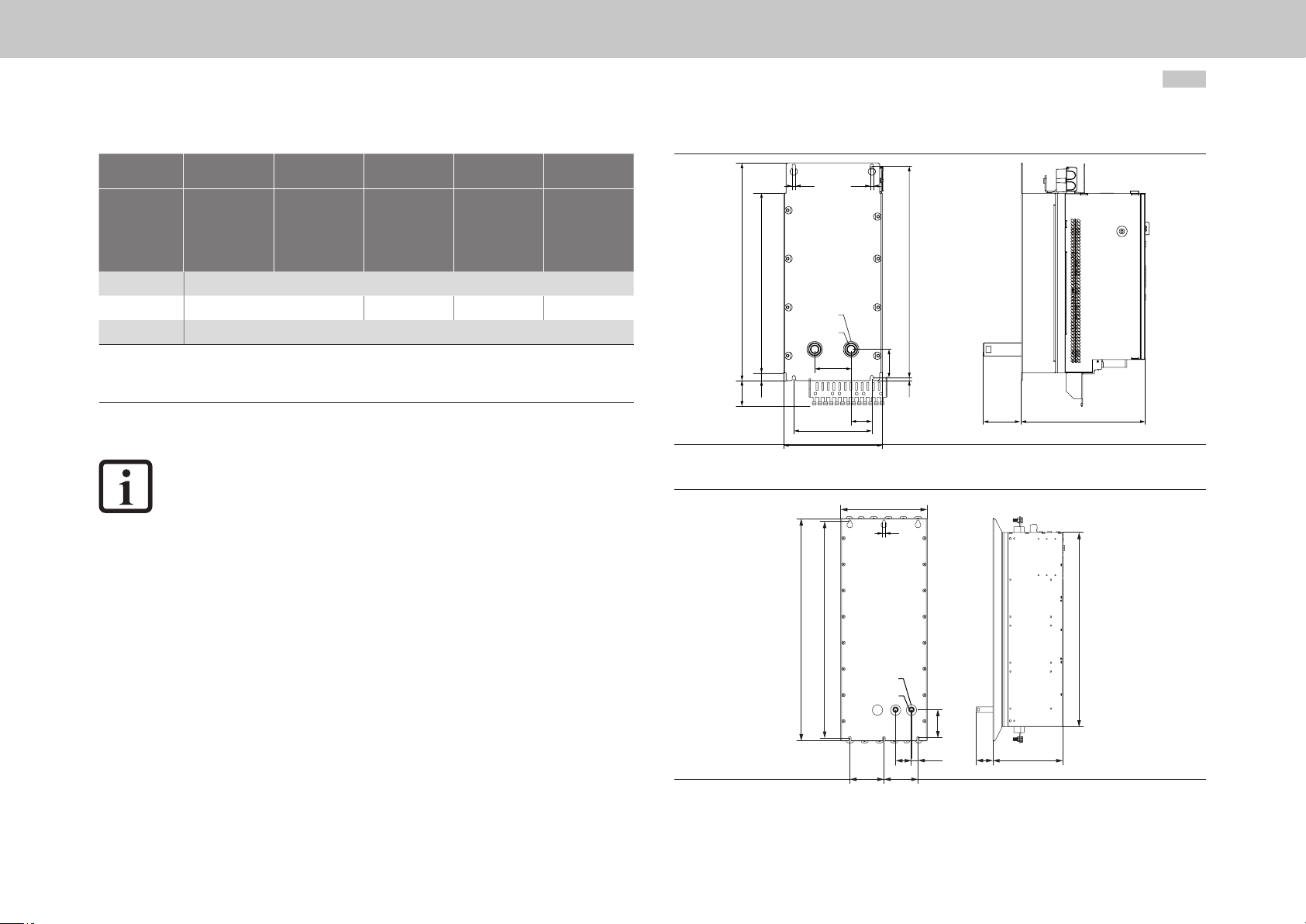
3.6 Mounting DC-AC Servo Drive
1.
2.
3.
4.
3.6.1 Dimensions and mounting clearances
liquid cooling housing variant
Arrange the devices starting from the Power Supply Unit to the right and/or left sorted in descending
order by power rating to minimise the thermal effects.
Align all devices in a line along the top edge of the devices so that the DC link coupling can be made
using the pre-assembled cables. Between the upper fastening screws for devices of Size 1 to Size 5
there is a vertical offset of 18.5mm (0.73in) compared to devices of size Size 6A (see Figure 3.5).
For information on the mounting clearances see Table 3.2.
Mark out the position of the tapped holes and the pipe ttings on the backing plate.
Drill holes and cut a thread for each xing screw in the backing plate.
Pay attention to the bending radius of the connection cables!
For hole spacing and dimensional drawings see Table 3.2, Figure 3.13 and Figure 3.14.
Mount the DC-AC Servo Drives vertically and side by side mounted in a row on the backing plate.
The contact area must be bare metal. Use the pre-assembled DC link cables supplied for the
DC power supply.
On screwing the hose connections (not included in the scope of supply) into the pipe ttings, lock the
pipe ttings using a 22mm (0.87in)open-ended wrench to prevent damage due to the application
of torque to the device.
Pay attention to a perfectly sealed connection without leaks (e.g. using Teon sealing tape).
Continue with the electrical installation in chapter4, page27.
Size Size 3 Size 4 Size 5 Size 6A Size 7
Device
G397-020
G397-025
Weight kg (lb) 6.5 (14.3) 7.5 (16.5) 13 (28.7) 32 (70.6) 100 (220.5)
B (width) 130 (5.12) 171 (6.73) 190 (7.48) 280 (11.02) 380 (14.96)
1)
H (height)
1)
D (depth)
A 80 (3.15) 120 (4.72) 150 (5.91) 200 (7.87) 150 (5.91)
A1 10 (0.39) 25 (0.98) 40 (1.57) 65 (2.56) 29 (1.14)
A2 60 (2.36) 70 (2.76)
C 382 (15.04) 406.5 (16) 581 (22.87) 952 (37.48)
C1 5 (0.2) 6 (0.24) 10 (0.39) 12 (0.47)
D (Ø) 4.8 (0.19) 6.5 (0.26) 9.5 (0.37) 12 (0.47)
D1 48 (1.89) (Ø hole for pipe socket)
E Direct side by side mounting, maximum 2 (0.08)
2)
F
2)
G
H1 392 (15.43) 418.5 (16.48) 600 (23.62) 971 (38.23)
H2 38.5 (1.52) 15 (0.59) 20 (0.79) 60 (2.36)
H3 70 (2.76) 70 (2.76) 54 (2.13) 56.5 (2.22) 124 (4.88)
All dimensions in mm (in)
1) Without terminals/connections
2) Also pay attention to the bending radius of the connection cables
295 (11.61) 346.5 (13.64) 540 (21.26) 952 (37.48)
224 (8.82) 238.5 (9.39) 285 (11.22) 286.5 (11.28)
≥150 (5.91) ≥180 (7.09)
G397-026
G397-035
≥300 (11.81) ≥500 (19.69)
G397-053
G397-070
G397-084
G397-110
G397-130
G397-170
G397-210
G397-250
G397-325
G397-450
moog
Id. no.: CA97554-001 05/2017
3 Mechanical installation
Table 3.2 Dimensions and mounting clearances, liquid cooling housing variant
MSD Multi-Axis System Operation Manual DC-AC Servo Drive
23
Page 24
B
3 Mechanical installation
moog
Id. no.: CA97554-001 05/2017
Size Size 3 Size 4 Size 5 Size 6A Size 7
Device
G397-020
G397-025
S [inch] 3/8 (female thread)
Screws 4 x M4 4 x M6 4 x M8 6 x M10
T1 73.5 (2.89)
All dimensions in mm (in)
1) Without terminals/connections
2) Also pay attention to the bending radius of the connection cables
Table 3.2 Dimensions and mounting clearances, liquid cooling housing variant
G397-026
G397-035
G397-053
G397-070
G397-084
G397-110
G397-130
G397-170
G397-210
NOTE:
The minimum distance specified in the table applies for devices of the same
power. On side by side mounting devices with different drive powers you
should arrange the devices in descending order by power rating (e.g., viewed
from the left, Size 4-Size 3-Size 2-Size 1). This arrangement will minimise the
thermal interaction. The Power Supply Unit must always be fitted beside the
DC-AC Servo Drive with the highest power.
On side by side mounting other devices to the multi-axis system, attention is
to be paid to ensuring there is no thermal interaction between the devices.
G397-250
G397-325
G397-450
MSD Multi-Axis System Operation Manual DC-AC Servo Drive
D
H1H4H
H2
Figure 3.13 Dimensional drawing, liquid cooling housing variant, based on Size 5 as an example
H1 C
D
C
D1
S
A2
A
B
H3
C1
A1
D
T1
T
H
24
D1
S
H3
T
A1A2
AA
Figure 3.14 Dimensional drawing, liquid cooling housing variant, based on Size 7 as an example
T1
Page 25
E
Figure 3.15 Mounting distance, liquid cooling housing variant, based on Size 5 as an example
F
F
G
F
F
Figure 3.16 Mounting distance, liquid cooling housing variant, based on Size 7 as an example
moog
Id. no.: CA97554-001 05/2017
E
G
3 Mechanical installation
MSD Multi-Axis System Operation Manual DC-AC Servo Drive
25
Page 26
3 Mechanical installation
moog
Id. no.: CA97554-001 05/2017
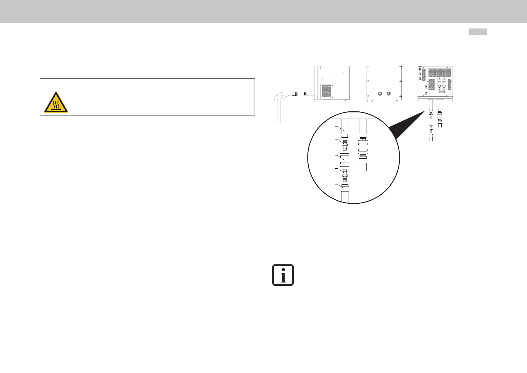
3.7 Cooling circuit connection
WARNING! Risk of injury due to hot coolant!
• Carelessness may result in serious burns.
In operation the coolant reaches high temperatures. Prior to starting work, make sure the coolant
has cooled down.
The devices with liquid cooling have a capacity of up to 0.5l of coolant depending on
the size. After the disconnection of the connections, liquid may be left in the device and
escape if the device is tipped. We recommend the usage of a self-sealing liquid coupling
(not included in the scope of supply) to prevent the coolant escaping and to make it
possible to disconnect and connect in the filled state
MSD Multi-Axis System Operation Manual DC-AC Servo Drive
1
2
3
4
5
1) Liquid connection with 3/8inch female thread
2) Self-sealing quick-release connection with 3/8inch male thread
3) Self-sealing liquid coupling
4) Adapter for hose connection
5) PUR (polyurethane) hose with clip
26
Figure 3.17 Cooling circuit connection, based on Size 6A as an example
NOTE:
Items2 to 5 are not included in the scope of supply and are to be ordered
separately.
Page 27
4 Electrical installation
4.1 Notes for installation
It is imperative you pay attention to the following warnings and safety instructions prior to
and during installation.
DANGER! Risk of injury due to electrical power!
• Carelessness will result in serious injuries or death.
Never wire or disconnect electrical connections while they are live! Before making any change
the device is to be disconnected from the mains. Even 10min. (Size 1 to 4) / 30min. (Size 5 to 7)
after mains off,
dangerously high voltages of ≥50V may still be present (capacitor charge). So
check that electrical power is not present!
Work on the device must only be carried out after the DC link voltage has dropped below a
residual voltage of 50V
(on Size 1 to 6A to be measured on the terminals X11/L+ and L-, on Size 7 on the terminals X11/
ZK- and X11/ZK+).
Dangerous voltage may be present at the device, even if the device is not emitting
any visual or audible signals/indications (e.g. with mains voltage applied to terminal X11 and
missing control supply +24V DC on X9/X10 or X44)!
WARNING! Risk of injury due to hot surfaces on the device (heat sink)!
• Carelessness may result in serious burns.
The device and especially the heat sink heat up signicantly during operation and can reach
temperatures of up to +100 °C (+212 °F). Prior to starting work, make sure the device has
cooled down.
On touching there is a risk of burns to the skin. For this reason provide protection against
touching.
During mounting maintain an appropriate distance to neighbouring assemblies.
NOTE:
Along with this operation manual, it is imperative the manuals for the Power
Supply Unit or the supplying AC-AC Servo Drive are read on installing the
complete MSD Multi-Axis System.
WARNING! Risk of injury due to hot coolant!
• Carelessness may result in serious burns.
In operation the coolant reaches high temperatures. Prior to starting work, make sure the coolant
has cooled down.
moog
Id. no.: CA97554-001 05/2017
4 Electrical installation
MSD Multi-Axis System Operation Manual DC-AC Servo Drive
27
Page 28

4 Electrical installation
moog
Id. no.: CA97554-001 05/2017
4.2 Effective EMC installation
4.2.1 Cable type
•
Use only shielded mains, motor and signal cables as shown in Figure 4.1. For all
shielded connections use cables with double copper braiding with 60 to 70%
coverage.
•
If it is necessary to lay very large cable cross-sections, instead of shielded
cables it is also possible to use separate individually shielded wires.
NOTE
Only use the DC link connections supplied for the electrical coupling of the
devices. If extending the DC link coupling is unavoidable, it is imperative you
pay attention to the requirements in chapterA.5, page103. On the usage of
connection cables that do not meet the requirements, Moog does not provide
any guarantee for stable, safe operation.
4.2.2 Routing of cables
You should take into account the following points on laying the cables:
•
Route mains, motor and signal cables separated from one another. Maintain a
distance of at least 200mm (7.87in).
•
For smaller distances use separators for shielding; fasten the separators directly
and conductively to the backing plate.
•
Route the cables close to ground potential. On the usage of cable ducts made
of plastic, the cable ducts must be fastened directly to the backing plates or the
frame. Open space must not be spanned, as otherwise the cables could act
like antennae.
•
Route motor cables without interruptions (e.g. not via terminals) and lay them by
the shortest route out of the switch cabinet.
•
If a motor contactor or a motor choke is used, the component should be
positioned directly at the DC-AC Servo Drive and the shielding on the motor
cable should not be stripped back too far.
•
Avoid unnecessary cable lengths and "loops of spare cable".
MSD Multi-Axis System Operation Manual DC-AC Servo Drive
•
Route long cables in places not be susceptible to interference. Otherwise
coupling points may be created.
•
Twist wires for the same electrical circuit.
•
Ideally, route the signal cables separated from encoder cables.
•
All signal cables should be combined and routed away upward.
•
Avoid extending cables via terminals.
28
4.2.3 Earthing measures
All earthed points and components must be routed directly to the central earthing
point (e.g. PE rail, main earth) with as low an impedance as possible and with good
conductivity. In this way an earthing system is produced that connects all connections to
the earthing point in a star topology. This central earthing point is to be clearly defined.
This earthing point can be extended to the entire backing plate with an effective EMC
connection.
You should take into account the following points for the earthing:
•
Earthed surfaces act as shielding measures and reduce electromagnetic fields
in the surrounding area. For this reason metal surfaces should be connected
to ground with low-impedance HF connections. In terms of EMC it is not the
cross-section of the cable that is definitive, but the surface over which high
frequency currents caused by the skin effect can flow awa .
•
Connect the protective earth conductors for the components in the switch
cabinet using a star topology.
•
Avoid the use of connectors.
•
Also connect the walls and doors of the switch cabinet to ground.
•
Larger openings in the switch cabinet (window, fan, display) degrade the
shielding effect of the cabinet and must be protected with additional shielding
measures for the HF range.
•
Earth unused cores at one end as a minimum so that there is no electrostatic
charging.
•
Free contact areas of paint and corrosion and make large area connections.
Page 29
•
The usage of tinned, galvanised, aluminised or cadmium-plated elements is to
be preferred over painted components; it will then not be necessary to remove
the paint. Connectors are to be avoided, or several contacts are to be used for
the shield connection in the connector.
For further information on the cross-section of the protective earth conductor see
chapter4.4, page36.
4.2.4 Shielding measures
You should take into account the following points for the shielding measures:
•
Use only shielded mains, motor and signal cables as shown in Figure 4.1,
page29. For all shielded connections use cables with double copper
braiding with 60 to 70% coverage.
•
Connect the shield at both ends using a large area connection. Extending the
shield to the earthing point using a wire (pigtail) reduces the shielding effect by
up to 90%.
Figure 4.1 CORRECT shield connection
Figure 4.3 Shield connection
•
Do not strip back too far the shield.
•
Shields are not allowed to be used to carry power, e.g. as a substitute for the N
or PE conductor.
•
The shielding effect can be improved by laying in metal ducts/tubes.
•
If it is necessary to lay very large cable cross-sections, instead of shielded
cables it is also possible to lay separate individually shielded wires.
•
Shields must be connected at one end as a minimum. Connection at
multiple points is recommended, otherwise potential equalisation currents
may flow in physically extensive installations. If the e is interference with long
ground connections, these can be connected using coupling capacitors.
These capacitors will provides a high-frequency connection for suppressing
interference without transmitting the 50-Hz components.
Figure 4.2 INCORRECT shield connection - do not extend to the earthing point (pigtail)
moog
Id. no.: CA97554-001 05/2017
4 Electrical installation
MSD Multi-Axis System Operation Manual DC-AC Servo Drive
29
Page 30
(Size 3 + 4)
(Size 1+2) SW
1.
2.
3.
4.
5.
4 Electrical installation
moog
Id. no.: CA97554-001 05/2017
4.2.5 External components
•
Place larger loads near the supply.
•
Contactors, relays, solenoid valves (switched inductances) must be wired with
suppressors. The wiring must be directly connected to the respective coil.
•
Any switched inductance should be at least 200mm (7.87in) away from the
process controlled assemblies.
If you require further detailed information on installation, please contact the Moog
Helpline.
4.3 Overview of the connections
Determine the terminal assignment that applies to your device.
For G393-004 (Size 1) to G393-032/G397-035 (Size 4) in chapter4.3.1, page30
For G393-045/G397-053 (Size 5) to G393-170/G397-210 (Size 6A) in chapter4.3.2, page32
For G397-250 to G397-450 (Size 7) in chapter4.3.3, page34
Connect all necessary input and output units to the control connections (chapter4.6, page38),
the optional interfaces (chapter4.11, page45) and/or (chapter4.12, page45) and the DC link
if necessary.
Connect encoder (chapter4.13, page46) and motor (chapter4.14, page49).
MSD Multi-Axis System Operation Manual DC-AC Servo Drive
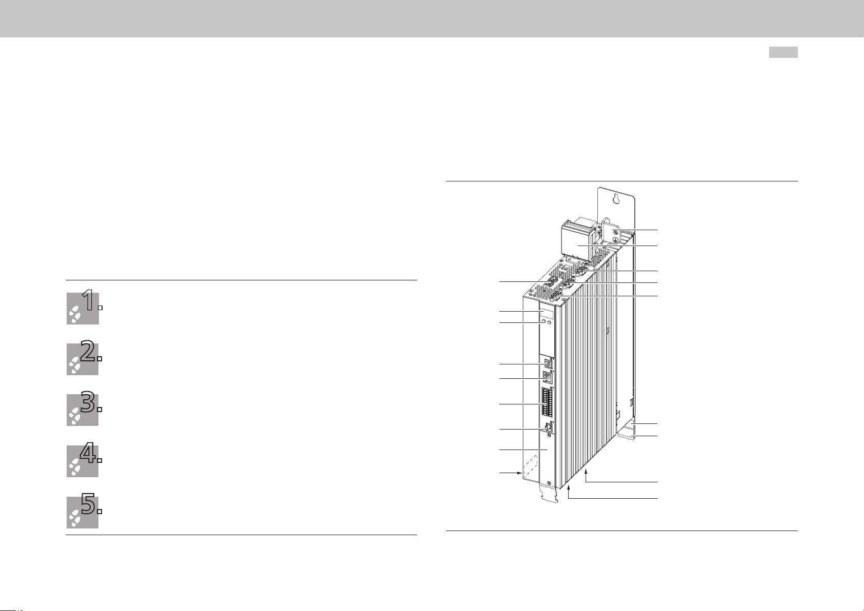
4.3.1 Layout, G393-004 (Size 1) to G393-032/G397-035 (Size 4)
In the following you will find the layout with the corresponding positions of the
connectors and terminals. For improved clarity we have added an abbreviation to the
designation for the connectors and terminals.
PE
X11
X8
X9, X10
D1, D2
T1, T2
X2
X3
X4
X7
X6
30
With the aid of the pre-assembled connection cables (DC-L), connect the protective earth conductor
(chapter4.4, page36) and the supply voltages (chapter4.7, page40).
Continue with commissioning in chapter5, page53.
X5
Option 1
HW: Hardware rating plate
SW: Software rating plate
Figure 4.4 Layout, G393-004 (Size 1) to G393-032/G397-035 (Size 4)
(based on G393-004 Size 1 as an example)
SW
HW
X12
X13
Page 31

Service
Top side
interface
Service
interface
Control
Analog setpoint 1
Analog setpoint 2
+24 V DC against
E/A-GND
Diagnosis
STO
Relay
Digital0
Digital1
Digital2
E/A-GND
Communication
Field buses
D1, D2
T1, T2
3
ISA00+
4
ISA00-
5
ISA01+
6
ISA01-
15
16
17
ISD03
18
ISD04
19
ISD05
20
ISD0621
10
22
12
11
23
24
7
OSD00
8
OSD01
9
1
DGND
2,14
13
DGND
USB 1.1
Ethernet
ISD00
ISD01
ISD02
ENPO (STO)
ISDSH (STO)
RSH
Relay
OSD04
OSD02
+24 V (U
H
Option 1
Abbreviation Designation Details
Encoder
Resolver
DC-L
PE
DC +
DC -
D1, D2 7-segment display chapter 5.4.2
T1, T2 Button chapter 5.4.1
X2 USB 1.1 interface chapter 4.9
)
V
X3 Ethernet interface chapter 4.10
X4 Control connections chapter 4.8
Option1 Communication chapter 4.11
X11 Connection for DC supply chapter 4.7
DC-L DC link cables chapter A.5
X2
X3
X4
X11
Danger!
X10
X9
X8
X7
X6
DC +
DC -
Option 2
54321
15 14 13 12 11
10 9876
4321
9876
DC-link
+
1
-
2
+
1
-
2
24 V DC Power supply
for control electronic (U
Technology
8
6
PE Connection for PE conductor chapter 4.4
Front
X5
+
-
X9, X10 Connection for control supply chapter 4.6
X8 (Option2) Technology chapter 4.12
Triggering of motorbrake
1
X13/1 do not connect!
GND
U
V
W
L-
L+
2
3
4
X13/4 do not connect!
DC-link
(Connect nothing!)
Motor
3
~
X13
X12
)
Danger!
X7 Connection for high-resolution encoder chapter 4.13
X6 Connection for resolver chapter 4.13.4
X5 Connection for motor temperature sensor chapter 4.14
X13 Connection for motor brake chapter 4.8.2
X12 Connection for motor chapter 4.14
Table 4.1 Key to layout and connection diagram, G393-004 (Size 1) to G393-032/G397-035
(Size 4)
Bottom side
Figure 4.5 Connection diagram, G393-004 (Size 1) to G393-032/G397-035 (Size 4)
moog
Id. no.: CA97554-001 05/2017
4 Electrical installation
MSD Multi-Axis System Operation Manual DC-AC Servo Drive
31
Page 32

4 Electrical installation
moog
Id. no.: CA97554-001 05/2017
4.3.2 Layout, G393-045/G397-053 (Size 5) to G393-170/ G397-210 (Size 6A)
In the following you will find the layout with the corresponding positions of the
connectors and terminals. For improved clarity we have added an abbreviation to the
designation for the connectors and terminals.
PE
X11
X20
X9, X10
X8
X7
X6
D1, D2
T1, T2
PE
X11
MSD Multi-Axis System Operation Manual DC-AC Servo Drive
X20
X9, X10
X8
X7
X6
D1, D2
T1, T2
X2
X3
X4
X5
32
X2
X3
X4
X5
SW
HW
Figure 4.6 Layout, G393-045/G397-053 to G393-072/G397-084 (Size 5, without shield plates)
Option 1
Option 1
SW
HW
X12
Figure 4.7 Layout, G393-090/G397-110 to G393-170/G397-210 (Size 6A, without shield plates)
Page 33

Top side
DC-L
Front
X11
only
BG 6a
X10
X9
X20
X8
X7
X6
X5
X12
Danger!
DC +
DC -
DC +
DC -
+24 V
OSD03
Option 2
54321
15 14 13 12 11
10 9876
4321
9876
GND
ZK+
ZK-
1
2
1
2
+
-
U
V
W
DC-link
+
-
+
-
1
2
3
only BG5:
DC link
(Connect nothing!)
24 V DC Power supply for
control electronic (U
24 V DC Power supply
for brake (I
= 2.0 A)
IN
Triggering for
motor brake
Technology
8
Encoder
6
Resolver
Motor
3
~
PE
DC +
DC -
DC +
DC -
)
V
Service
interface
Service
interface
Control
Analog setpoint 1
Analog setpoint 2
+24 V DC against
DGND
Diagnosis
Digital0
Digital1
Digital2
E/A-GND
Communication
Field buses
Relay
STO
D1, D2
T1, T2
USB 1.1
Ethernet
3
ISA00+
4
ISA00-
5
ISA01+
6
ISA01-
15
ISD00
16
ISD01
17
ISD02
18
ISD03
19
ISD04
20
ISD05
ISD0621
10
ENPO(STO)
22
ISDSH(STO)
12
RSH
11
23
Relay
24
OSD04
7
OSD00
8
OSD01
9
OSD02
1
DGND
2
+24 V (U
14
13
DGND
Option 1
)
H
Danger!
X2
X3
X4
Bottom side
Figure 4.8 Connection diagram, G393-045/G397-053 (Size 5) to G393-170/G397-210 (Size 6A)
Abbreviation Designation Details
D1, D2 7-segment display chapter 5.4.2
T1, T2 Button chapter 5.4.1
X2 USB 1.1 interface chapter 4.9
X3 Ethernet interface chapter 4.10
X4 Control connections chapter 4.8
Option1 Communication chapter 4.11
X11 Connection for DC supply chapter 4.7
DC-L DC link cables chapter A.5
PE Connection for PE conductor chapter 4.4
X9, X10 Connection for control supply chapter 4.6
X8 (Option2) Technology chapter 4.12
X7 Connection for high-resolution encoder chapter 4.13
X6 Connection for resolver chapter 4.13.4
X5 Connection for motor temperature sensor chapter 4.14
X20 Connection for motor brake chapter 4.8.2
X12 Connection for motor chapter 4.14
HW Hardware rating plate Figure 4.6
SW Software rating plate Figure 4.7
Table 4.2 Key to connection diagram, G393-045/G397-053 (Size 5) to G393-170/G397-210
(Size 6A)
moog
Id. no.: CA97554-001 05/2017
4 Electrical installation
MSD Multi-Axis System Operation Manual DC-AC Servo Drive
33
Page 34

Brake (+)
Top side
T
ZK−
W
4 Electrical installation
moog
Id. no.: CA97554-001 05/2017
MSD Multi-Axis System Operation Manual DC-AC Servo Drive
34
4.3.3 Layout, G397-250 to G397-450 (Size 7)
In the following you will find the layout with the corresponding positions of the
1
connectors and terminals. For improved clarity we have added an abbreviation to the
designation for the connectors and terminals.
ZK−
ZK+
ZK+
PE
PE
X11
X45
X44
X8
D1, D2
X7
X6
1, T2
X2
X3
X4
X5
Option 1
SW
HW
RB−
RB+
PE
X12
U
V
Service
interface
Service
interface
Control
ENPO
Communication
Field buses
2
,
D
D
1
2
,
T
T
USB 1.1
X2
Ether net
X3
X4
3
ISA00+
4
ISA00-
5
ISA01+
6
ISA01-
15
ISD00
16
ISD01
17
ISD02
18
ISD03
ISD04
19
ISD05
20
ISD0621
10
ENPO
22
ISDSH
12
RSH
11
23
Relay
24
OSD04
7
OSD00
8
OSD01
9
OSD02
1
DGND
2
+24V(U
)
14
13
H
DGND
Option 1
X11
Danger!
X45
Danger!
X44
X8
X7
X6
X5
Front
X12
Danger!
Bottom side
Option 2
5 4321
15 14 13 12 11
10 9876
4321
9876
ZK−
ZK−
ZK+
ZK+
PE
PE
1
2
3
4
5
6
7
+
-
+
-
W
V
U
Dc link
via DC-Link cables
Reserved
+
–
Reserved
+24 V
OSD03
GND
5
9
Reserved
24 V Power supply for
control electronic (UV)
24 V DC Power supply
for brake (IIN = 2.0 A)
Triggering for
mitir brake
e. g. add. encoder
8
Encoder
6
Resolver
Motor
3~
(+)
Brake (-)
Figure 4.9 Layout, G397-250 to G397-450 (Size 7, without shield plates)
Figure 4.10 Connection diagram, G397-250 to G397-450 (Size 7)
Page 35

Abbreviation Designation Details
D1, D2 7-segment display chapter 5.4.2
T1, T2 Button chapter 5.4.1
X2 USB 1.1 interface chapter 4.9
X3 Ethernet interface chapter 4.10
X4 Control connections chapter 4.8
Option1 Communication chapter 4.11
X11 Connection for DC supply chapter 4.7
DC-L DC link cables chapter A.5
PE Connection for PE conductor chapter 4.4
Connection for control supply chapter 4.6
X44
Connection for motor brake chapter 4.8.2
X8 (Option2) Technology chapter 4.12
X7 Connection for high-resolution encoder chapter 4.13
X6 Connection for resolver chapter 4.13.4
X5 Connection for motor temperature sensor chapter 4.14
X12 Connection for motor chapter 4.14
HW Hardware rating plate Figure 4.9
SW Software rating plate Figure 4.9
Table 4.3 Key to connection diagram (Size 7)
moog
Id. no.: CA97554-001 05/2017
4 Electrical installation
MSD Multi-Axis System Operation Manual DC-AC Servo Drive
35
Page 36

1.
2.
4 Electrical installation
moog
Id. no.: CA97554-001 05/2017
4.4 Protective earth conductor connection
Earth each of the DC-AC Servo Drives!
The following applies for the PE connection according to IEC/EN61800-5-1
(as leakage current >3.5mA):
• Use a protective earth conductor with the same cross-section as the mains cables, however at
least 10mm² (0.016 in²) copper.
Also take into account the local and national regulations and conditions.
On operation with a Power Supply Unit:
• G393-004 (Size 1) to G393-072/G397-084 (Size 5)
− Connect the PE connections on the DC-AC Servo Drives and the Power Supply Unit together
using the pre-assembled cables.
− Connect the Power Supply Unit to the PE rail (main earth) in the switch cabinet.
• G393-090/G397-110 (Size 6A) to G397-450 (Size 7)
− Connect each DC-AC Servo Drive directly to the PE rail (main earth) in the switch cabinet.
− Connect the Power Supply Unit directly to the PE rail (main earth) in the switch cabinet.
On operation with an AC-AC Servo Drive as the supply:
• G393-004 (Size 1) to G393-072/G397-084 (Size 5)
− Connect the PE connections on the DC-AC Servo Drives together using the pre-assembled
cables. Do NOT connect the PE connection on a DC-AC Servo Drive to the PE connection
on the supplying AC-AC Servo Drive, instead directly to the PE rail (main earth) in the switch
cabinet.
− Connect the AC-AC Servo Drive directly to the PE rail (main earth) in the switch cabinet.
• G393-090/G397-110 (Size 6A) to G397-450 (Size 7)
− Connect each DC-AC Servo Drive directly to the PE rail (main earth) in the switch cabinet.
− Connect the AC-AC Servo Drive directly to the PE rail (main earth) in the switch cabinet.
MSD Multi-Axis System Operation Manual DC-AC Servo Drive
36
4.5 Electrical isolation concept
The control electronics, with their logic (µP), the encoder terminals and the inputs and
outputs, are electrically isolated from the power section (power supply/DC link). All
control terminals are designed as safety extra low voltage/protective extra low voltage
(SELV/PELV) circuits and must only be operated with such SELV/PELV voltages, as per
the relevant specification. This p ovides reliable protection against electric shock on the
control side.
The control electronics therefore require a separate control supply that corresponds to
the requirements of a SELV/PELV.
The overview opposite shows the potential references for the individual connections in
detail.
This concept also delivers higher operational safety and reliability of the DC-AC Servo
Drive.
NOTE
The terminal X5 (terminal assignment) represents a special case in relation to
insulation and isolation. On this topic follow the instructions in chapter4.14,
page49 .
SELV = Safety Extra Low Voltage
Also connect the protective earth conductor connections on all other components, such as mains
lter1) etc. in a star topology to the PE rail (main earth) in the switch cabinet.
1) The components are only required for the Power Supply Unit.
You will find an example for the p otective earth conductor connections in Figure 4.17,
page41.
PELV = Protective Extra Low Voltage
Page 37

24V DC
OSD03
Motorbrake
GND
X20/1
X20/2
X20/3
#)
#)
#) only for hardware
versions 0 and 1
Up to hardware version 2
replaced by 0 Ω each.
#)
PE GNDµP
DGND
complexe,
impedance in
part non lineare
RC
element
Polyswitch
GNDµP
GNDµP
GNDµP
X4/15
ISD00
ISD01
I
LIM
X4/21
ISD06
X4/10
ENPO
I
LIM
X4/22
ISDSH
I
LIM
X4/7
OSD00
X4/3
ISA00+
PTC of the motor
X4/4
ISA00-
ISD02
ISD03
ISD04
ISD05
A/D
A/D
ISA01+
X4/5
X4/6
ISA01-
X4/14
GNDµP
GNDµP
GNDµP
GNDµP
GNDµP
DGND
DGND
DGND
DGND
DGND
DGND
DGND
DGND
X4/2
ϑ
F1
ϑ
F2
X4/13
DGND
X4/1
ϑ
F3
ϑ
F3
GNDµP
GNDµP
GNDµP
ϑ
F4
V
µP
V
µP
V
µP
V
µP
µP
X4/8
OSD01
X4/9
OSD02
54
321
98
76
54321
10 9876
15 14
13 12
11
X5/ϑ +
X5/ϑ −
RS H
X4/12
X4/11
OSD0 4
X4/23
X4/24
USB1.1
X2
Ethernet
X3
Resolver
X6
Encoder/SSI
X7
GNDµP
V
µP
PE
U
V
U
V
X9/+
X9/-
X10/+
X10/-
U
H
Control
supply
+24 V DC
X13/1
ϑ
X13/2
X13/3
X13/4
ϑ
Motorbrake
#)
#)
PE GNDµP
DGND
complexe,
impedance in
part non lineare
RC
element
Polyswitch
GNDµP
GNDµP
GNDµP
X4/15
ISD00
ISD01
I
LIM
X4/21
ISD06
X4/10
ENPO
I
LIM
X4/22
ISDSH
I
LIM
X4/7
OSD00
X4/3
ISA00+
PTC of the motor
X4/4
ISA00-
ISD02
ISD03
ISD04
ISD05
A/D
A/D
ISA01+
X4/5
X4/6
ISA01-
X4/14
GNDµP
GNDµP
GNDµP
GNDµP
GNDµP
DGND
DGND
DGND
DGND
DGND
DGND
DGND
DGND
X4/2
ϑ
F1
ϑ
F2
X4/13
DGND
X4/1
ϑ
F3
ϑ
F3
GNDµP
GNDµP
GNDµP
ϑ
F4
V
µP
V
µP
V
µP
V
µP
µP
X4/8
OSD01
X4/9
OSD02
54
321
98
76
54321
10 9876
15 14
13 12
11
X5/ϑ +
X5/ϑ −
RSH
X4/12
X4/11
OSD04
X4/23
X4/24
USB1.1
X2
Ethernet
#) only for hardware
versions 0 and 1
Up to hardware version 2
replaced by 0 Ω each.
X3
Resolver
X6
Encoder/SSI
X7
GNDµP
V
µP
PE
U
V
U
V
X9/+
X9/-
X10/+
X10/-
U
H
Control
supply
+24 V DC
#)
Id. no.: CA97554-001 05/2017
Figure 4.11 Electrical isolation concept, Size 1 to Size 4
moog
4 Electrical installation
Figure 4.12 Electrical isolation concept, Size 5 and Size 6A
MSD Multi-Axis System Operation Manual DC-AC Servo Drive
37
Page 38

24V DC
+24V DC
GND
OSD03
Motorbrake
GND
X44/5
X44/6
X44/7
#)
#)
#) only for hardware
versions 0 and 1
Up to hardware version 2
replaced by 0 Ω each.
#)
PE GNDµP
DGND
complexe,
impedance in
part non lineare
RC
element
Polyswitch
GNDµP
GNDµP
GNDµP
X4/15
ISD00
ISD01
I
LIM
X4/21
ISD06
X4/10
ENPO
I
LIM
X4/22
ISDSH
I
LIM
X4/7
OSD00
X4/3
ISA00+
PTC of the motor
X4/4
ISA00-
ISD02
ISD03
ISD04
ISD05
A/D
A/D
ISA01+
X4/5
X4/6
ISA01-
X4/14
GNDµP
GNDµP
GNDµP
GNDµP
GNDµP
DGND
DGND
DGND
DGND
DGND
DGND
DGND
DGND
X4/2
ϑ
F1
ϑ
F2
X4/13
DGND
X4/1
ϑ
F3
ϑ
F3
GNDµP
GNDµP
GNDµP
ϑ
F4
V
µP
V
µP
V
µP
V
µP
µP
X4/8
OSD01
X4/9
OSD02
54
321
98
76
54321
10 9876
15 14
13 12
11
X5/ϑ +
X5/ϑ −
RSH
X4/12
X4/11
OSD04
X4/23
X4/24
USB1.1
X2
Ethernet
X3
Resolver
X6
Encoder/SSI
X7
GNDµP
V
µP
PE
U
V
X44/1
X44/2
U
H
Control
supply
24 V DC
4 Electrical installation
moog
Id. no.: CA97554-001 05/2017
Figure 4.13 Electrical isolation concept, Size 7
MSD Multi-Axis System Operation Manual DC-AC Servo Drive
38
4.6 Connection of control supply (+24VDC)
The supply of power to the DC-AC Servo Drive is separate for the control section and
power section. The control supply is always to be connected rst in the sequence
so that the operation of the DC-AC Servo Drive can be checked first and the device
parameters configu ed for the planned application.
NOTE:
Dimension the control supply to suit the maximum current required. Pay
attention to the general wiring rules on the topic of cable protection.
NOTE:
On the sizes Size 1 to Size 4, along with the control section the external power
supply also supplies the output for the motor holding brake. If this output is
active, the current for the control section plus the current for the motor holding
brake, in addition to any current required for digital inputs and outputs, flows
via terminal X9. Pay attention to this issue on dimensioning the power supply
for the control section and on looping through to other devices. You will find
the current required by the individual devices in chapter A.4.
NOTE:
Do not use the connector as a "switch" for a reset.
Page 39

4.6.1 G393-004 (Size 1) to G393-170/G397-210 (Size 6A)
y
Top side
Top side
Device 1
Device 2
D1 D2
X11
X9
X10
DC power supply DC power suppl
DC +
DC -
1
2
1
2
maximum
10 A gG
+
-
+
-
+24 V DC ± 20 %
external voltage
supply
Looping only possible
for Size 1 to Size 4
Figure 4.14 Connection for control supply
Terminal/pin Specication
• U
=+24VDC -20% +10%, stabilised and smoothed
V
• For maximum starting and continuous currents see chap.A.4
X9/1 = +
X9/2 = -
• Fuse protection for the terminal maximum10A
• Internal polarity reversal protection
• The Power Supply Unit used must have safe and reliable isolation in relation to the mains
as per EN50178 or IEC/EN61800-5-1.
• Connected internally to X10
X10/1 = +
X10/2 = -
• Connected internally to X9
Table 4.4 Specication, control supply Size 1 to Size 6A
D1 D2
X11
X9
X10
DC +
DC -
+
1
-
2
+
1
-
2
next servo drive
4.6.2 G397-250
to G397-450 (Size 7)
Terminal/pin Specication
=+24VDC -20% +10%, stabilised and smoothed
• U
V
• For max. starting and continuous currents see chap.A.4
X44/1 = +
X44/2 = -
• Fuse protection for the terminal max.10A
• Internal polarity reversal protection
• The Power Supply Unit used must have safe and reliable isolation in relation to the mains
as per EN50178 or IEC/EN61800-5-1.
Table 4.5 Specication, control supply Size 7
moog
Id. no.: CA97554-001 05/2017
4 Electrical installation
MSD Multi-Axis System Operation Manual DC-AC Servo Drive
39
Page 40

1.
2.
3.
4 Electrical installation
moog
Id. no.: CA97554-001 05/2017
4.7 Connection of DC power supply
Make sure all DC-AC Servo Drives are arranged in a row and side by side mounted.
See installation instructions in chapter 3
Use the pre-assembled connection cables supplied for the DC power supply to the DC-AC Servo
Drives. Via the terminals X11 connect together all (+) connections and all (−) connections.
The pre-assembled connection cables supplied are as long as the related device is wide.
You will nd more detailed information on the mains connection for the Power Supply Unit in the
Operation Manual MSD Power Supply Unit.
NOTE:
Only use the DC link connections supplied for the electrical coupling of the
devices. If extending the DC link coupling is unavoidable, it is imperative you
pay attention to the requirements in chapter A.5. On the usage of connection
cables that do not meet the requirements, Moog does not provide any
guarantee for stable, safe operation.
NOTE:
Before commissioning, set the value for the supply voltage connected in the
DC-AC Servo Drive.
MSD Multi-Axis System Operation Manual DC-AC Servo Drive
Figure 4.15 Detail: connection, DC power supply Size 5
40
Figure 4.16 Detail: connection, DC power supply Size 6A or Size 7 to smaller DC-AC Servo
Drives
Page 41

8 9 10
L1
L1.1
L2
L2.1
L3
L3.1
L2
L1
6
L2.1
L1.1
5
L2
L1
4
L2.1
L1.1
3
2
L3
L3.1
L3
L3.1
Key
L1.1
L1
L2.1
L2
L3.1
L3
7
11
24 V DC
PE
12
13
max. 8 A
14
nc
HREL
15
X5
L1 L2
X21
L3 N
+ −
X11
− +− +
X9/10
+ − − +− +− +− +
+ −
X11X11
X9/10X9/10
16 19 19
L1 L2
X12
L3
ZK RB
+ −− +
EtherCAT
UVW
EtherCAT
X12X12
UVW
1) Mains fuses
2) Mains supply/emergency stop
3) Shield plates (grey)
4) Step-up choke with KTY
temperature sensor
5) Shielded cables should be used from
>500mm cable length
6) Input choke with lm capacitor
7) Mains contactor (after precharging via HREL)
8) Mains lter
9) Short circuit proof cables
10) Circuit breaker
11) Multi-axis system on/off
12) External +24VDC control supply
13) Auxiliary contactor (precharging/
synchronisation)
14) Connection, DC link precharging and mains
synchronisation
15) Floating contact: 250VAC/5A or
30VDC/6A (active, once precharging
complete)
16) MSD Power Supply Unit Size 6A
17) AC mains connection
18) Braking resistor
19) MSD Servo Drive DC-AC
20) Switch cabinet
21) Field
1
L1 L2 L3 PE
17
18
ϑ
Figure 4.17 Connection of power supply and control supply as well as protective earth conductor in the axis group (example)
moog
Id. no.: CA97554-001 05/2017
4 Electrical installation
20
21
Motor
3~
Motor
3~
MSD Multi-Axis System Operation Manual DC-AC Servo Drive
41
Page 42

Des.
Term.
Specication
Electrical isolation
REL
REL
ISDSH
ISD06
ISD05
ISD04
ISD03
ISD02
ISD01
ISD00
+24V
DGND
RSH
RSH
ENPO
OSD02
OSD01
OSD00
ISA1-
ISA1+
ISA0-
ISA0+
+24V
DGND
X4
1.
2.
3.
4.
5.
6.
4 Electrical installation
moog
Id. no.: CA97554-001 05/2017
4.8 Control connections
Check whether a complete device setup is already available, i.e. whether the drive has already been
congured.
If this is the case, a special control terminal assignment applies.
Please contact your project engineer to obtain the terminal assignment!
Choose a terminal assignment.
Wire the control terminals using shielded cables.
The following are imperative: request STO X4/22, ENPO X4/10 and a start signal (with control via
terminal).
Ground the cable shields over a wide area at both ends.
Cable cross-sections 0.2 to 1.5mm² (0.0003 to 0.002 in²), with ferrules with plastic sleeve
max.0.75mm² (0.001 in²)
Keep all contacts open (inputs inactive).
Check all connections again!
MSD Multi-Axis System Operation Manual DC-AC Servo Drive
4.8.1 Specification of the cont ol connections
Analog inputs
ISA0+
ISA0−
ISA1+
ISA1−
Digital inputs
ISD00
ISD01
ISD02
ISD03
ISD04
ISD05
ISD06
Table 4.6 Specication of the control connections X4
X4/3
X4/4
X4/5
X4/6
X4/15
X4/16
X4/17
X4/18
X4/19
X4/20
X4/21
• U
• Resolution 12bits; R
• Terminal scan cycle in the "IP mode" 125µs, otherwise
1ms
• Tolerance: U±1% of the measuring range end value
• Standard input
• Frequency range <500Hz
• Sampling cycle: 1ms
• Switching level low/high: ≤4.8V/≥18V
• I
MAX
Touchprobe or standard input
• Input for touchprobe for quickly saving process data
(e.g.actual position)
− Internal signal delay
− Activation via ISD05/ISD06 = 15(PROBE)
• Standard input
− Frequency range ≤500Hz
− Sampling cycle: 1ms
• U
• I
IN max
• Switching level low/high: ≤4.8V/≥18V
=±10VDC
IN
at+24V = 3mA typ.
Hardware version 0..1 Min. Max. Typ.
ISD05 3µs 16µs 8µs
ISD05
ISD06
From hardware version 2 Min. Max. Typ.
ISD05 +
ISD06
= +24VDC +20%
IN max
at+24VDC =10mA, RIN=approx. 3kΩ
approx.101kΩ
IN
4µs 27µs 15µs
2µs
2µs
No
Yes
Yes
42
24
12
23
11
22
10
21
9
20
8
19
7
18
6
17
5
16
4
15
3
14
2
13
1
Page 43

X4/23
IN
REL
REL
ISDSH
ISD06
ISD05
ISD04
ISD03
ISD02
ISD01
ISD00
+24V
DGND
RSH
RSH
ENPO
OSD02
OSD01
OSD00
ISA1-
ISA1+
ISA0-
ISA0+
+24V
DGND
X4
IN
X4/12
Des. Term. Specication Electrical isolation
ENPO X4/10 • Disable the restart inhibit (STO) and enable the power
Yes
stage = high level
Digital outputs
OSD00
OSD01
OSD02
X4/7
X4/8
X4/9
• OSSD support (from hardware version 2)
• Response time approx. 10ms
• Switching level low/high: ≤4.8V / ≥18V
• U
= +24VDC +20%
IN max
• I
at +24VDC = typ. 3mA
• No irreparable damage in the event of a short circuit
(+24V -> GND), however, device may briey shut down
• I
=50mA, PLC-compatible
MAX
• Terminal scan cycle in=1ms
Yes
24
23
22
21
20
19
18
17
16
15
14
13
• High-side driver
STO ("Safe Torque Off") *)
ISDSH
(STO)
X4/22 • Input "Request STO" = low level
• OSSD support (from hardware version 2)
Yes
• Switching level low/high: ≤4.8V / ≥18V
• U
= +24VDC +20%
IN max
• I
at +24VDC = typ. 3mA
RSH
RSH
X4/11
X4/12
Diagnostics STO, both shut-off channels
active, one NO contact with automatically
X4/11
Yes
resetting circuit breaker (polyswitch)
• 25V/200mAAC, cosϕ=1
• 30V/200mADC, cosϕ=1
*) STO certification applies for DC-AC Servo Drives of size Size 1 to Size 7
Table 4.6 Specication of the control connections X4
Des. Term. Specication Electrical isolation
Relay outputs
12
11
10
9
8
7
6
5
4
3
2
1
REL X4/23
Auxiliary voltage
+24V X4/2
X4/24
X4/14
Relay, 1 NO contact
• 25V/1.0AAC, cosϕ=1
• 30V/1.0ADC, cosϕ=1
• Switching delay approx.10ms
• Cycle time1ms
• Auxiliary voltage for supplying the digital control inputs
= UV-∆U (∆U typically approx.1.2V), no irreparable
• U
H
damage in event of short circuit (+24V -> GND), but
device may briey shut down.
• I
=80mA (per pin) with self-resetting circuit breaker
MAX
(polyswitch)
X4/24
Yes
Yes
Digital ground
DGND X4/1
Reference ground for +24V, I
X4/13
versions 0..1 with self-resetting circuit breaker (polyswitch)
=80mA (per pin), hardware
MAX
Yes
Table 4.6 Specication of the control connections X4
NOTE
High-impedance isolation in the relation to device ground
If excessively high currents flow via the earth terminals, high-impedance
isolation from the device ground is possible. In some circumstances this can
result in the malfunction of the drive. To prevent this situation arising, avoid
currents circulating in the wiring.
NOTE:
Take into account that in the event of a fault, the Power Supply Unit may no
longer be able to feed regenerative energy from the DC-AC Servo Drive to
the mains. To prevent irreparable damage to the Power Supply Unit's braking
resistor on extended regenerative operation, the DC-AC Servo Drives and the
Power Supply Unit can be mutually interlocked via terminal X4. You will find
further information and an example circuit in chapter10.1, page85.
moog
4 Electrical installation
Id. no.: CA97554-001 05/2017
MSD Multi-Axis System Operation Manual DC-AC Servo Drive
43
Page 44

X20
+24
X44
+24 V DC
BR+
BR-
4
4 Electrical installation
Id. no.: CA97554-001 05/2017
moog
4.8.2 Brake driver
G393-004 (Size 1) to G393-032/G397-035 (Size 4)
The connector X13 is intended to be used to connect a motor brake.
Des. Term. Specication Connection
• Short circuit proof
• Power is supplied via the control supply U
X9 or X10
• U
=UV-∆U`(∆U`typically approx.1.4V)
BR
+24V
BR+
BR−
GND
X13/1
X13/2
X13/3
X13/4
• For operating a motor holding brake up to
I
=2.0Amaximum, for brakes with a
BR
higher current requirement a relay must be
connected in between.
• Overcurrent causes shutdown
• Can also be used as congurable digital
output.
• Congurable cable break monitoring
<500mA in state "1" (up to the relay)
Table 4.7 Specication of the terminal connections X13
V
on
X13
1
2
3
Brake (+)
Brake (-)
M
MSD Multi-Axis System Operation Manual DC-AC Servo Drive
G393-045/G397-053 (Size 5) to G393-170/G397-210 (Size 6A)
The connector X20 is intended to be used to connect a motor brake.
Des. Term. Specication Connection
+24 V DC power supply
for brake (I
+24 V DC
+24V
OSD03
GND
X20/1
X20/2
X20/3
• Short circuit proof
• External power supply
24VDC (IIN=2.1A) required
• For operating a motor holding brake up to
I
=2.0Amaximum, for brakes with a
BR
higher current requirement a relay must be
connected in between
• Overcurrent causes shutdown
V DC 1
OSD03 2
GND 3
• Congurable cable break monitoring
<200mA in state "1" (up to the relay)
Table 4.8 Specication of the terminal connections X20
G397-250 to G393-450 (Size 7)
The connector X44 is intended to be used to connect a motor brake.
= 2.1 A)
IN
M
44
Brake (-)
Brake (+)
Des. Term. Specication Connection
+24V
OSD03
GND
• Short circuit proof
• External power supply
X44/5
• For operating a motor holding brake up to
X44/6
X44/7
+24VDC (IIN=2.1A) required
I
=2.0Amaximum, for brakes with a higher
BR
current requirement a relay must be connected in between
1
OSD03 2
GND 3
• Overcurrent causes shutdown
• Congurable cable break monitoring <200mA
in state "1" (up to the relay)
Table 4.9 Specication of the terminal connections X44
+24 V DC power supply
for brake (IIN = 2.1 A)
M
+24 V DC
Brake (-)
Brake (+)
Page 45

4.9 Specification, USB interface
4.12 Option2
The service and diagnostics interface X2 is designed as a USB V1.1 interface. It is only
suitable for connecting a PC for commissioning, service and diagnostics using the
software Moog
Technical specification
•
•
DriveADministrAtor5.
USB1.1standard - full speed device interface
Connection via commercially available USB interface cable typeA to typeB
4.10 Specification, Ethernet interface
The service and diagnostic interface X3 is designed as an Ethernet interface. It is only
suitable for connecting a PC for commissioning, service and diagnostics using the
software Moog
Technical specification
•
•
•
DriveADministrAtor5.
Transfer rate 10/100 Mbits/s BASE-T
Transmission profile IEEE802.3 complian
Connection via commercially available crosslink cable CAT5
4.11 Option1
Depending on the DC-AC Servo Drive variant, Option1 is factory-congured with various
options. Field bus options such as EtherCAT or SERCOS are available.
Option2 can be factory-congured with various technology options. Additional or special
encoders can be evaluated here for example.
You will find all available options in the MSD Ordering Catalog. The User Manuals for
the respective options provide detailed information on commissioning.
You will find all available options in the MSD Ordering Catalog. The User Manuals for
the respective options provide detailed information on commissioning.
moog
Id. no.: CA97554-001 05/2017
4 Electrical installation
MSD Multi-Axis System Operation Manual DC-AC Servo Drive
45
Page 46

4 Electrical installation
moog
Id. no.: CA97554-001 05/2017
4.13 Encoder connection
All encoder connections are located on the top of the unit.
4.13.1 Encoder connection for synchonous motors
Please use the ready made motor and encoder cables from Moog to connect the
synchronous motors.
4.13.2 Allocation of motor/encoder cable to the DC-AC Servo Drive
Compare the rating plates of the components. Make absolutely sure you are using the
correct components according to variant A, B or C!
Variant
C
X7 (optional X8 )
X6
Variant
A
Variante
B
high-resolution encoder with HIPERFACE® interface
high-resolution encoder with SSI-/EnDat interface
MSD Multi-Axis System Operation Manual DC-AC Servo Drive
Motor (with encoder installed) Encoder cable
Variant A
Variant B
Variant C
Table 4.10 Variants of motors, encoder type and encoder cable
With resolver
without further options
Sin/Cos multi-turn encoder
with SSI/EnDat interface
Sin/Cos multi-turn encoder
with HIPERFACE® interface
C08335-013-yyy X6
CA58876-002-yyy X7
CA58877-002-yyy X7
Connection on the
DC-AC Servo Drive
NOTE:
Do not cut the encoder cable, for example to route the signals via terminals in
the switch cabinet. The knurled screws on the D-Sub connector housing must
be tightly locked!
4.13.3 Ready made encoder cables
The specications can only be assured when using the Moog system cables.
Encoder cable
Ready made-up cable
Resolver cable
Encoder cable SSI, EnDat CA58876
Encoder cable Hiperface
Encoder system
Version
Cable length (m)
1) yyy stands for length in meters; standard length: 1 m (3.28 ft), 5 m (16.40 ft), 10 m (32.80 ft), 15 m (49 ft), 20 m (65 ft), 50 m
(164 ft). Further length on request
Encoder cable CO8335-013-yyy
1)
CO8335 - 013 - yyy
® CA58877
Order code
002
002
46
Resolver
Figure 4.18 Motor/encoder cable assignment
Page 47

Technical data
Technical data CO8335-013-yyy
Motors with
encoder system
Controller-end
assignment (sub-D
connector)
Capable for energy
chains
Minimum bend
radius
Resolver
1 = S3
2 = S1
3 = S2
4 = n.c.
5 = PTC+
6 = R1
7 = R2
8 = S4
9 = PTC-
90mm (3.54 in) 100mm (3.93 in) 90mm (3.54 in)
1)
CA58876-002-yyy
G3, G5, G12.x
(single-turn / multi-turn
encoder with
SSI/EnDat interface)
1 = A2 = A+
3 = VCC (+5V)
4 = DATA+
5 = DATA6 = B8 = GND
11 = B+
12 = VCC (Sense)
13 = GND (Sense)
14 = CLK+
15 = CLK7, 9, 10 = n.c.
yes
1)
CA58877-002-yyy
G6, G6.x
(single-turn / multi-turn
encoder with
HIPERFACE® interface)
1 = REFCOS
2 = +COS
7-12V
3 = U
s
4 = Data+ EIA485
5 = Data- EIA485
6 = REFSIN
7 = Jumper to PIN12
8 = GND
11 = +SIN
12 = Jumper to PIN7
9, 10, 13, 14, 15 = n.c.
4.13.4 Resolver connection
1)
A resolver is connected to slot X6 (9-pin D-Sub socket).
Figure X6/pin
Resolver S3 differential input (reference to Pin X6-2)
1
Resolver S1 differential input (reference to Pin X6-1)
X6
Resolver
9 8 7 6
5 4 3 2 1
1) It is imperative attention is paid to the warning
2
Resolver S2 differnetial input (reference to Pin X6-8)
3
Supply voltage 5..12V, connected internally to X7/3
4
ϑ+ (PTC, NTC, KTY Klixon)
5
Ref+ analog excitation
6
Ref- analog excitation (ground reference point to pin6)
7
Resolver S4 differntial input (reference to Pin X6-3)
8
ϑ− (PTC, NTC, KTY Klixon)
9
Table 4.12 Pin assignment X6
Function
1)
1)
Temperature range
Cable diameter
approx.
Material of outer
sheath
-40 to +85°C
(-40 to +185°F)
-35 to +80°C
(-31 to +176°F)
8.8mm (0.34 in)
PUR
-40 to +85°C
(-40 to +185°F)
Resistance Resistant to oil, hydrolysis and microbic attack (VDE0472)
Approvals
UL-Style 20233, +80°C (+176°F)-300V,
CSA-C22.2N.210-M90, +75°C (+167°F)-300VFT1
Table 4.11 Technical data encoder cable
moog
Id. no.: CA97554-001 05/2017
4 Electrical installation
CAUTION! Damage to the device due to incorrect insulation of the motor winding!
• Carelessness can cause damage to the motor/device
The motor temperature sensor (PTC, also NTC, KTY and Klixon) must be provided with basic
insulation in relation to the motor winding on connection to X5, on connection to X6 with
reinforced insulation as per IEC/EN 61800-5-1.
MSD Multi-Axis System Operation Manual DC-AC Servo Drive
47
Page 48

X7
Encoder/ SSI
4 Electrical installation
Id. no.: CA97554-001 05/2017
moog
4.13.5 Connection for high-resolution encoders
The interface X7 makes possible the evaluation of the following encoder types.
Figure Function
Sin/Cos encoder with zero pulse
X7
Encoder/ SSI
Table 4.13 Suitable encoder types on X7
NOTE:
• The usage of encoders not included in the range supplied by Moog
• The maximum signal input frequency is 500kHz.
• Encoders with a power supply of 5V ±5% must have a separate sensor
Select the cable type specified by the motor or encoder manufactu er. During this
process bear in mind the following boundary conditions:
•
Always used shielded cables. Connect the shield at both ends.
•
Connect the differential track signals A/B, R or CLK, DATA using twisted pair
cable cores.
e.g. Heidenhain ERN1381, ROD486
Heidenhain Sin/Cos encoder with EnDat interface
e.g. 13 bit single-turn encoder (ECN1313.EnDat01) and 25 bit multi-turn encoder
(EQN1325-EnDat01)
Heidenhain encoder with digital EnDat interface
Single- or multi-turn encoder
Sin/Cos encoder with SSI interface
e.g. 13 bit single-turn and 25 bit multi-turn encoder (ECN413-SSI, EQN425-SSI)
Sick-Stegmann Sin/Cos encoder with HIPERFACE® interface
Single- and multi-turn encoder, e.g. SRS50, SRM50
requires special approval by Moog.
cable connection. The sensor cable detects the actual supply voltage at
the encoder; it is then possible to compensate for the voltage drop on
the cable. Only by use of the sensor cable is it ensured that the encoder
is supplied with the correct voltage. The sensor cable must always be
connected.
MSD Multi-Axis System Operation Manual DC-AC Servo Drive
Do not cut the encoder cable, for example to route the signals via terminals in
the switch cabinet.
Sin/Cos
absolute
value
encoder
Fig. X7 pin
Sin/Cos
and TTL
SSI/EnDat
1 A- A- - REFCOS
2 A+ A+ - +COS
+5VDC ±5%, I
(150mA for hardware versions 0..1), monitoring
3
4 - Data + Data + Data +
5 - Data - Data - Data -
6 B- B- - REFSIN
54321
Table 4.14 Pin assignment for the connector X7
7 - - - U
15 14 13 12 11
10 9876
8 GND GND GND GND
9 R- - - -
10 R+ - - -
11 B+ B+ - +SIN
12 Sense + Sense + Sense + U
13 Sense - Sense - Sense - -
14 - CLK+ CLK+ -
15 - CLK - CLK - -
OUTmax
via sensor cable
Absolute
value
encoder
EnDat
(digital)
=250mA
Absolute
value
encoder
HIPERFACE®
7 to 12V
(typ. 11V)
max. 100mA
- switch
S
- switch
S
The sum of the
currents drawn at
X7/3 and X6/4 must
not exceed the value
given!
After connecting pin 7
to pin 12, a voltage of
11.8V is set on X7,
pin3!
48
Page 49

NOTE:
1.
2.
3.
The encoder supply on X7/3 is short circuit proof on both 5V and 11V
operation. The controller remains in operation enabling the generation of a
corresponding error message on evaluating the encoder signals.
4.14 Motor connection
Dene the cable cross-section according to local and national regulations and conditions. It is
dependent on the rated current, the type of cable laying and the ambient temperature.
4.14.1 Motor connection for synchronous motors
NOTE:
To connect the servomotors in the product range please use a ready made
motor cable from Moog.
G393-004 (Size 1) to G393-032/G397-035 (Size 4)
NOTE
Recommended connection option for a motor brake with a motor brake
current of maximum2A see Figure 4.19.
Connect the shielded motor cable to terminals X12/ U, V, W and connect the motor to earth at .
Connect the shield at both ends to prevent interference emissions.
Fasten shield connection plate for the motor connection X12 using both screws.
Wire the temperature sensor, if tted, to terminal X5 using separate shielded cables and activate the
temperature evaluation using Moog DriveADministrAtor5.
Connect the shield at both ends to prevent interference emissions.
CAUTION! Damage to the device due to incorrect insulation of the motor winding!
• Carelessness can cause damage to the motor/device
The motor temperature sensor must, in relation to the motor winding, on connection to X5 be
provided with basic insulation as per IEC/EN 61800-5-1.
NOTE:
In the event of a short circuit or earth fault in the motor cable, the power stage
is disabled and an error message is issued.
GND
+
-
U
V
W
1
2
3
4
Triggering of motor brake
(maximum 2 A)
Motor
3
~
5
X
12
X
13
X
Figure 4.19 Connection of the motor for Size 1 to Size 4 (motor brake to2A)
moog
Id. no.: CA97554-001 05/2017
4 Electrical installation
MSD Multi-Axis System Operation Manual DC-AC Servo Drive
49
Page 50

4 Electrical installation
moog
Id. no.: CA97554-001 05/2017
NOTE:
Connection option for a motor brake with a motor brake current of
maximum2A see Figure 4.20. Cable break detection is not possible.
GND
+
-
U
V
W
1
2
3
4
Triggering of
motor brake
24 V DC
+
Motor
3
~
+24 V DC
Power supply
for brake
Brake (−)
Brake (+)
5
X
12
X
13
X
Figure 4.20 Connection of the motor for Size 1 to Size 4 (motor brake from2A)
G393-045/G397-053 (Size 5) to G393-170/G397-210 (Size 6A)
MSD Multi-Axis System Operation Manual DC-AC Servo Drive
G397-250 to G397-450 (Size 7)
+24 V
OSD03
GND
+
-
U
V
W
Triggering of
motor brake
5
6
7
−
+
24 V DC
Brake (+)
Brake (−)
+
Motor
3
~
5
X
12
X
44
X
+24 V DC Power
supply for brake
(I
= 2.1 A)
IN
Figure 4.22 Connection of the motor for G397-250 to G397-450 (Size 7)
Ready made motor cable
50
+24 V
OSD03
GND
+
-
U
V
W
Triggering of
motor brake
1
2
3
−
+
24 V DC
Brake (+)
Brake (−)
+
Motor
3
~
5
X
12
X
20
X
+24 V DC Power
supply for brake
(IIN = 2.1 A)
Figure 4.21 Connection of the motor for G393-045/G397-053 (Size 5) to G393-170/G397-210
(Size 6A)
CO8336 - xxx yyy
Ready made-up motor cable
Conguration option
Cable l ength (m)
1) yyy stands for length in meters; standard length: 1 m (3.28 ft), 5 m (16.40 ft), 10 m (32.80 ft), 15 m (49 ft), 20 m (65 ft), 50 m
(164 ft). Further length on request
1)
Motor cable CO8336-xxx-yyy Order code
Page 51

Technical data
Technical data C08336-xxx-yyy
Continuous rated
current
Cable cross-section
Temperature range
Wiring
Connector type Size 1 Size 1 Size 1
1) yyy stands for length in meters; standard length: 1 m (3.28 ft), 5 m (16.40 ft), 10 m (32.80 ft), 15 m (49 ft), 20 m (65 ft), 50 m (164 ft). Further length on request
2) xxx-001 for standard configuration option, further options on equest
Table 4.15 Technical data motor cab
4 x 1,5mm² + 2 x 1mm²
(4 x 0.0024 in² + 2 x 0.0016 in²)
Connector pin Wiring Connector pin Wiring Connector pin Wiring Connector pin Wiring Connector pin Wiring
Connector
housing
10A TBD 44A 61A 82A
-40bis +125°C
(-40 to +275 °F)
2 U 2 U U U U U U U
4 VV 4 VV V VV V VV V VV
1 WWW 1 WWW W WWW W WWW W WWW
PE yellow / green PE yellow / green PE yellow / green PE yellow / green PE yellow / green
5 Brake + / white 5 Brake + / white + Brake - / white + Brake + / white + Brake + / white
6 Brake - / black 6 Brake - / black - Brake - / black - Brake - / black - Brake - / black
1),2)
Monitor
CB05708-xxx-yyy
4 x 4mm² + 2 x 1,5mm²
(4 x 0.0062 in² + 2 x 0.0023 in²)
TBD
Connector
housing
1),2)
Monitor
CA44958-xxx-yyy
4 x 6mm² + 2 x 1,5mm²
(4 x 0.0093 in² + 2 x 0.0023 in²)
-50bis +90°C
(-58 to +194 °F)
Connector
housing
1),2)
Monitor
CB00076-xxx-yyy
4 x 10mm² + 2 x 1,5mm²
(4 x 0.00155 in² + 2 x 0.0023 in²)
TBD TBD
Connector
housing
Size 1 Size 1
1),2)
Monitor
CA98676-xxx-yyy
4 x 16mm² + 2 x 1,5mm²
(4 x 0.0248 in² + 2 x 0.0023 in²)
Connector
housing
1),2)
Monitor
NOTE:
Cores 5 and 6 (PTC) are required only for motors in which the motor PTC
cannot be connected via the encoder cable. In the case of servomotors with
resolver, the PTC is connected via the resolver cable.
moog
Id. no.: CA97554-001 05/2017
4 Electrical installation
MSD Multi-Axis System Operation Manual DC-AC Servo Drive
51
Page 52

4 Electrical installation
moog
Id. no.: CA97554-001 05/2017
4.14.2 Switching in the motor cable
CAUTION! Damage to the device due to switching in the motor cable!
• Carelessness can cause damage to the device
Motor cable switching must take place with the power switched off and the power stage disabled,
as otherwise problems such as burnt contactor contacts or
damage to the power stage may occur.
To ensure unpowered switch-on, you must make sure that the contacts on the motor
contactor are closed before the DC-AC Servo Drive power stage is enabled. At the
moment when the contactor is switched off it is necessary for the contact to remain
closed until the DC-AC Servo Drive's power stage is shut down and the motor current
is 0. This is achieved by using appropriate safety delays for the switching of the motor
contactor in the control sequence for your machine.
Despite these measures, the possibility cannot be ruled out that the DC-AC Servo Drive
may malfunction during switching in the motor cable.
MSD Multi-Axis System Operation Manual DC-AC Servo Drive
52
Page 53

5 Commissioning
1.
2.
3.
4.
5.
5.1 Notes for commissioning
5.2 Initial commissioning
Once the DC-AC Servo Drive has been installed as described in chap. 3 and wired with
all required power supplies and external components as described in chap. 4, initial
commissioning can performed in the following sequence:
It is imperative you pay attention to the following warnings and safety instructions prior to
and during installation.
WARNING! Risk of injury due to hot surfaces on the device (heat sink)!
• Carelessness may result in serious burns.
The device and especially the heat sink heat up signicantly during operation and can reach
temperatures of up to +100°C (+212°F). Prior to starting work, make sure the device has
cooled down.
On touching there is a risk of burns to the skin. For this reason provide protection against
touching.
During mounting maintain an appropriate distance to neighbouring assemblies.
WARNING! Risk of injury due to hot coolant!
• Carelessness may result in serious burns.
In operation the coolant reaches high temperatures. Prior to starting work, make sure the coolant
has cooled down.
CAUTION! Damage to the device due to incorrect installation conditions!
The device may suffer irreparable damage.
Therefore during operation
• Moisture must not be allowed to enter the device
• There must not be any aggressive or conductive substances in the ambient air
• Foreign bodies such as drilling chips, screws, washers etc. must not be allowed to fall into
the device
• The ventilation openings must not covered
Install and start the PC software Moog DriveADministrAtor5.
You will nd more detailed information in the Installation Manual Moog DriveADministrAtor 5.
Switch on the control supply (chapter5.2.1).
Connect the DC-AC Servo Drive to the PC (chapter5.2.2).
Congure the parameters (chapter5.2.3).
Test the drive using Moog DriveADministrAtor5 (chapter5.2.4).
NOTE:
Details in relation to "STO" (Safe Torque Off) do not need to be taken into
account for initial commissioning. You will find all information on the STO"
function in the 24-language document "Description of the STO Safety
Function" (ID no. CB19388).
moog
Id. no.: CA97554-001 05/2017
5 Commissioning
MSD Multi-Axis System Operation Manual DC-AC Servo Drive
53
Page 54

3.
4.
2.
5 Commissioning
moog
Id. no.: CA97554-001 05/2017
5.2.1 Switching on control supply
To initialise and congure parameters, initially only switch on the +24V control supply. Do not yet
switch on the power supply.
Display indication after switching on the control supply
D1 D2 Action Explanation
Switching on the ext. +24V control supply Initialisation in progress
Initialisation completed Not ready to switch on
Table 5.1 Switch-on status of the DC-AC Servo Drive on connection of the +24VDC control
supply
NOTE:
You will find details on the control supply in chapter4.6.
You will find details on the display indication in chapter5.4.
MSD Multi-Axis System Operation Manual DC-AC Servo Drive
5.2.2 Connection between PC and DC-AC Servo Drive
The PC can be connected to the DC-AC Servo Drive via USB or Ethernet (TCP/IP). Connect PC and
DC-AC Servo Drive using the related connection cable.
NOTE:
• Initialisation
The communication link between PC and DC-AC Servo Drive can only be
set up after the servo drive has completed its initialisation.
• USB driver and TCP/IP configuration
If the PC does not recognise the DC-AC Servo Drive connected, please
check the driver and the settings for the related interface (see Installation
Manual Moog
DriveADministrAtor 5).
5.2.3 Configuring parameter
The commissioning wizard in Moog DriveADministrAtor 5 is provided for making the settings for the
drive system. Start the wizard.
54
NOTE:
• Online help
You will find a detailed description of Moog
commissioning wizard in the online help for Moog DriveADministrAtor5.
• Motor data set
On using Moog Synchronous Motors of type the latest
version of the motor data set required can be obtained from
http://www. moogsoftwaredownload.com/msd.html “Motor
Configuration files".
DriveADministrAtor5 and the
Page 55

5.2.4 Controlling drive using Moog DriveADministrAtor5
5.
Display indication after switching on the power supply
Switch on the power supply. Then enable the power stage and activate the control. The drive should
be tested without the coupled mechanism.
DANGER! Risk of injury due to rotating parts on the motor!
• Carelessness may result in serious injuries or death.
Before commissioning motors with feather keys in the shaft end, these keys must be reliably
secured against throwing out, if this is not already prevented by drive elements such as belt
pulleys, couplings or similar.
CAUTION! Damage to the motor due to incorrect operation during motor test run!
• Carelessness can result in signicant damage to the motor or
machine.
• It is imperative the safety instructions and warnings from chapter 2 are followed during
commissioning. Please note that you yourself are responsible for safe operation.
• Before you start commissioning it must be ensured that the machine will not be damaged by
the test! Pay particular attention to the limitations of the positioning range.
• Certain motors are only intended for operation on the servo drive. Direct connection to the
mains supply can cause irreparable damage to the motor.
• The motor surfaces may become extremely hot. No temperature sensitive parts may touch
or be fastened to these areas, appropriate measures to prevent contact must be applied
wherever necessary.
• To avoid overheating of the motor, the temperature sensor installed must be connected to the
terminals of the temperature monitoring system for the servo drive also during the test run.
• The motor holding brake (if installed) should be checked for correct function before
commissioning the motor. Motor holding brakes are only designed for a limited number of
emergency braking operations. Use as working brake is not allowed.
D1 D2 Action Reaction Explanation
Switching on the
power supply
Table 5.2 Display D1, D2 after switching on the power supply
NOTE:
• Inputs "ISDSH" and "ENPO"
For step1 in Table 5.1 at least the two inputs"ISDSH" and "ENPO on
terminal X4 must be connected.
• Ready to operate
On operation with an AC-AC Servo Drive as the supply, all DC-AC Servo
Drives in the system must be in state 2 (ready to operate) before the first
axis starts.
• Manual mode window
Step2 in Table 5.1 is best undertaken via the "Manual mode" window in
DriveADministrAtor5. You will find details in the Online Help
Moog
• Configuration of the inputs/output
If step2 is to be implemented via the inputs on terminal X4, the sources for
"START CONTROL" and speed setpoint must be configu ed accordingly in
"Inputs/Outputs" in Moog
Controller ready,
power stage ready,
control deactivated
DriveADministrAtor5.
Device is ready for switching
on
moog
Id. no.: CA97554-001 05/2017
5 Commissioning
MSD Multi-Axis System Operation Manual DC-AC Servo Drive
55
Page 56

1
0
t
1
0
0
t
0
1
0
˜2 ms
DRIVE READY
t
0
1
0
5 Commissioning
moog
Id. no.: CA97554-001 05/2017
Power-up sequence for starting the drive
1. Deactivate the safety function "STO"
by setting the inputs
"ISDSH" and "ENPO"
2. Activate “START CONTROL” at the earliest
2ms after step1
and specify the speed setpoint
3. Monitor your system or plant and
check the drive behaviour.
t = motor dependent delay
ISDSH (STO)
ENPO (STO)
START
t
(STATE 5)
MSD Multi-Axis System Operation Manual DC-AC Servo Drive
56
Display reading after starting the drive
D1 D2 Action Reaction Explanation
"STO" and power stage
"ENPO" enabled
PAY ATTENTION TO WARNING PRIOR TO THE "START" STEP!
"Start" enabled Drive ready
Table 5.4 D1, D2 indication during activation of motor
CAUTION!
Damage to your system/machine due to uncontrolled or
inappropriate commissioning.
• Carelessness may result in damage to your system/
machine.
Before the next step, "Enable start", it is imperative you specify a plausible setpoint via the analog
input! The setpoint set is transferred to the drive immediately after the motor control has started.
For details on adjusting the drive to your application, please refer to the Online Help for
DriveADministrAtor5 and the Device Help.
Moog
Ready to switch on Power stage ready
Motor energised,
control active
Table 5.3 Power-up sequence
5.3 Serial commissioning
An existing parameter data set can be transferred to other DC-AC Servo Drives using
DriveADministrAtor5. You will find details on this topic in the Online Help for Moog
Moog
DriveADministrAtor5 and in chapter5.4.
NOTE:
MSD PLC programs can only be loaded into an DC-AC Servo Drive using the
programming system CODESYS.
Page 57

5.4 Integrated control unit
The integrated control unit permits diagnostics on the DC-AC Servo Drive. The control
unit comprises the following elements, all located on the front of the device:
•
2-digit 7-segment display (D1, D2)
•
Two buttons (T1, T2)
D1
D2
T2
T1
The following functions and displays are available:
•
Indication of the device status (see chapter6.1.1)
The device status is indicated after switching on the control supply. If no input
is made via the keypad for 60seconds, the display switches back to the
indication of the device status.
•
Indication of the device error status (see chapter6.1.2)
On the occurrence of an error in the device, the display is immediately switched
to the indication of the error code.
•
Parameter setting (indication "PA") (see chapter5.4.3)
The device parameter configuration can be eset to the factory settings.
•
Ethernet IP address setting (indication "IP") (see chapter5.4.4)
Ethernet IP address and subnet mask setting
•
Field bus settings (indication "Fb") (see chapter5.4.5)
E.g. field bus add ess setting
Figure 5.1 Integrated control unit
moog
Id. no.: CA97554-001 05/2017
5 Commissioning
MSD Multi-Axis System Operation Manual DC-AC Servo Drive
57
Page 58

5 Commissioning
moog
Id. no.: CA97554-001 05/2017
5.4.1 Function of buttons T1 and T2
These buttons are used to activate the different menus and to control the corresponding
functions.
Button Function Comment
• Activate the menu (exit the device
T1 (left)
T2 (right)
T1 and T2
together
General
Table 5.5 Function of buttons T1 and T2
status display)
• Scroll through the menus/sub-menus
• Set values - left segment display (D1)
• Selection of chosen menu
• Set values - right segment display (D2)
• Menu level up
• Accept selection
• Acknowledge
The button T1 can be held pressed for any
length of time because the display will only
scroll through the menu commands available
at the corresponding level. No settings will
be changed.
The button T2 must not be held pressed
for any length of time because the display
will change from one menu level to the next
within the menu structure and then change
the parameter that is reached at the end. You
should therefore always release the button
T2 after each change in display.
After pressing T1 and T2 at the same time,
the value applied ashes for ve seconds.
During this time the save procedure can still
be aborted by pressing any button, without
applying the value set. Otherwise the new
value will be saved after ve seconds.
• The time the button needs to be held
depressed until an action is executed, is
approx. 1 second.
• If there is no action by the user for a
period of 60seconds, the display returns
to the indication of the device status.
MSD Multi-Axis System Operation Manual DC-AC Servo Drive
58
5.4.2 Display
The following table defines various indications and items of status information p ovided
via the display.
Display Meaning
Menu entries
("PA" in this case serves as an example, for further possible entries see
chapter5.4.4 and chapter5.4.5)
[Flashing decimal points]
Selected function in progress
[Two dashes]
Entry/function not available
[OK]
Action executed successfully, no errors
[Error]
• Action via control unit not executed successfully,
"Er" ashes alternately with the error number
(see chap.chapter5.4.3)
• Device error indication,
"Er" ashes alternately with error number and error location (see "MSD Servo
Drive Device Help")
Numerical values
("10" in this case serves as an example)
• Data set and error numbers are shown in decimal on the Parameter menu
(PA).
• All other values are displayed in hexadecimal. In these cases the 10
displayed would represent the decimal value 16.
Table 5.6 Meaning of display
NOTE:
If no input is made via the keyboard for a period of 60s, the display returns to
the indication of the device status.
Page 59

5.4.3 Parameter menu (PA)
5.4.4 Ethernet IP address menu (IP)
The following functions are available on the Parameter menu:
•
Reset device to factory settings
Menu level Pa-
1 2
PA Pr - - Parameter reset Reset device settings to factory settings.
Table 5.7 Parameter menu
rame-
ter
Value
range
Meaning Explanation
Error messages displayed during user data entry
A failed user action is indicated by an error message. The message consists of the
alternating display of "Er" and the error number.
NOTE:
The error messages displayed during user data entry should not be confused
with drive error messages. You will find detailed information on the er or codes
and on error management in the Device Help.
Error number Meaning
17 Parameter reset to factory settings failed
18 Parameter write access failed
19 Save parameter data set non volatile failed
20 Not all parameters written
21 Error while reset to factory settings
Table 5.8 Error messages displayed during user data entry
An Ethernet TCP/IP interface is available as a service and diagnostics interface. The IP
address is set in the factory to 192.168.39.5. It can be changed using the PC software
DriveADministrAtor5 or via the display.
Moog
Menu level Pa-
1 2
IP Iu b0 00..FF
Table 5.9 IP address menu
rame-
Ir - -
Su b0 00..FF
Sr - -
Value
range
ter
b1 00..FF
b2 00..FF
b3 00..FF
b1 00..FF
b2 00..FF
b3 00..FF
Meaning Explanation
IP address
update byte0
IP address
update byte1
IP address
update byte2
IP address
update byte3
IP reset to
factory setting
Subnet mask
update byte0
Subnet mask
update byte1
Subnet mask
update byte2
Subnet mask
update byte3
Subnet mask
reset to
factory setting
Setting for byte0 of the IP address in
hexadecimal format
(e.g. "5" in 192.168.39.5)
Setting for byte1 of the IP address in
hexadecimal format
(e.g. "27" for 192.168.39.5)
Setting for byte2 of the IP address in
hexadecimal format
(e.g. "A8" for 192.168.39.5)
Setting for byte 3 of the IP address in
hexadecimal format
(e.g. "C0" at 192.168.39.5)
Reset IP address to factory setting
(192.168.39.5)
Setting for byte0 of the subnet mask in
hexadecimal format
(e.g. "0" in 255.255.255.0)
Setting for byte1 of the subnet mask in
hexadecimal format
(e.g. "FF" in 255.255.255.0)
Setting for byte2 of the subnet mask in
hexadecimal format
(e.g. "FF" in 255.255.255.0)
Setting for byte3 of the subnet mask in
hexadecimal format
(e.g. "FF" in 255.255.255.0)
Reset subnet mask to factory setting
(255.255.255.0)
moog
Id. no.: CA97554-001 05/2017
5 Commissioning
MSD Multi-Axis System Operation Manual DC-AC Servo Drive
59
Page 60

several actuations
5 Commissioning
moog
Id. no.: CA97554-001 05/2017
Example configuration of the subnet mask
In this example the subnet mask is changed from 255.255.255.0 to 122.255.255.0.
of buttonTx (X = 1, 2)
Tx
until the desired menu
appears in the display
single actuation
Tx
of button Tx (X = 1, 2)
Actuation of
any button
simultaneous actuation
T1 T2
of both buttons T1 and T2
T1 T2
T1 T2
T1 T2
T1 T2
T1 T2
T1
back
T2
back
T1
back
T2
back
T1
back
T2
MSD Multi-Axis System Operation Manual DC-AC Servo Drive
NOTE:
• During the flashing phase after step7 the save procedure can still be
aborted by pressing any button, without applying the value set. Otherwise
the new value will be saved after five seconds
• The modified IP add ess is only effective after restarting the control
electronics (24-V reset).
5.4.5 Field bus address menu (Fb)
The functions available on this menu item depend on the device's communication
option. For detailed information refer to the relevant specification
Menu level Pa-
1 2
rame-
Fb Ad -
Po -
Table 5.10 Field bus address menu
ter
Value
range
00..xx
or
- -
0..3
or
- -
Meaning Explanation
Setting for eld bus address
(only if eld bus option used), otherwise indication
Field bus address
"- -"
(The maximum value that can be programmed
depends on the option)
Setting for bre-optic power output
Transmit power
(only with SERCOS II option),
otherwise indication "- -"
60
T1 T2
Value NOT
saved
<5 s
back
Figure 5.2 Example conguration of the subnet mask
T1 T2
T1
T1 T2
<5 s
T2
accept
Value
saved
>5 s>5 s
Page 61

Example configuration of the field bus ad ess
In this example the field bus add ess is changed from 1 to 23.
several actuations
of buttonTx (X = 1, 2)
Tx
until the desired menu
appears in the display
single actuation
Tx
of button Tx (X = 1, 2)
Actuation of
any button
simultaneous actuation
T1 T2
of both buttons T1 and T2
T1 T2
T1 T2
T1
back
T2
back
T2
T1 T2
Value NOT
saved
<5 s
back
T1
<5 s
Figure 5.3 Example conguration of the eld bus address
T1 T2
>5 s>5 s
accept
T1 T2
T2
Value
saved
moog
Id. no.: CA97554-001 05/2017
5 Commissioning
MSD Multi-Axis System Operation Manual DC-AC Servo Drive
61
Page 62

5 Commissioning
moog
Id. no.: CA97554-001 05/2017
MSD Multi-Axis System Operation Manual DC-AC Servo Drive
62
Page 63

6 Diagnostics
6.1.2 Error indication
The specific er or codes are indicated via the 7-segment display. Each error code
comprises the alternating sequence → "Er" → error number→ error location.
6.1 Status indication on the device
The device states are shown on the device using the 7-segment display.
6.1.1 Device states
Display System status
Device in reset state
Self-initialisation on device startup
1)
Not ready to switch on (no DC link voltage)
1)
Start inhibit (DC link OK, power stage not ready
Ready to switch on (power stage ready)
Switched on (power applied to drive)
Drive ready (power applied to drive and drive ready for setpoint input)
Quick-stop
3)
2)
2)
3)
3)
Display Meaning
Device error
↓ Display changes after approx.1s
Error number (decimal)
Example: 05 = Overcurrent
↓ Display changes after approx.1s
Error location (decimal)
Example: 01 = Hardware monitoring
↑ After approx.1s the display changes back to ER
Table 6.2 Display of the error code
NOTE:
• Acknowledge error
The errors can be acknowledged according to their programmed reaction
(ER) or only by means of a 24V reset (ER.). Errors marked with a point can
only be reset once the cause of the error has been rectified
• Error code
You will find detailed information on the er or codes and on error
management in the MSD Servo Drive Device Help.
Error response active
1) This not a "safe indication" in the context of IEC/EN61800-5-2.
2) S. ashes if the function STO (Safe Torque Off) is active, indication extinguishes if function is inactive.
3) The point ashes if the power stage is active.
Table 6.1 Device states
moog
Id. no.: CA97554-001 05/2017
3)
6 Diagnostics
MSD Multi-Axis System Operation Manual DC-AC Servo Drive
63
Page 64

6 Diagnostics
moog
Id. no.: CA97554-001 05/2017
6.2 Status and error indication in
Moog
Click the "Device status" button in the header in the Moog DriveADministrAtor5 to open
the "Device status" window.
Figure 6.1 "Device status" button in the header
Use the "Error historyto" button to retrieve information on the last 20 errors that have
occurred.
DriveADministrAtor5
MSD Multi-Axis System Operation Manual DC-AC Servo Drive
On the occurrence of an error, a "pop-up" window appears immediately with more
detailed information on the actual error.
64
Figure 6.2 "Device status" window
Figure 6.3 Error message
Page 65

“Alarms & Warnings (Details)” contains detailed
information on an error or warning that has
occurred.
1. Double-click in the project tree “Alarms &
Warnings (Details)”.
NOTE:
You will find further information in the
program help for
DriveADministrAtor 5.
Moog
1
Figure 6.4 “Alarm & Warnings (Details)”
moog
Id. no.: CA97554-001 05/2017
6 Diagnostics
MSD Multi-Axis System Operation Manual DC-AC Servo Drive
65
Page 66

6 Diagnostics
moog
Id. no.: CA97554-001 05/2017
MSD Multi-Axis System Operation Manual DC-AC Servo Drive
66
Page 67

7 Safe Torque Off (STO)
NOTE:
You will find all information on the STO" function in the 24-language
document "Description of the STO Safety Function" (ID no. CB19388).
NOTE:
STO certification applies for DC-AC Servo Drives of Size 1 to 7
moog
Id. no.: CA97554-001 05/2017
7 Safe Torque Off (STO)
MSD Multi-Axis System Operation Manual DC-AC Servo Drive
67
Page 68

7 Safe Torque Off (STO)
moog
Id. no.: CA97554-001 05/2017
MSD Multi-Axis System Operation Manual DC-AC Servo Drive
68
Page 69

8 Operation with AC-AC Servo Drive
as supply
8.1.1 Device protection
During the installation of a multi-axis system with AC-AC Servo Drive as the supply, pay
attention to the following information on device protection:
NOTE
Planning
You will find help with the selection of the optimal operation mode (with Power
Supply Unit or with AC-AC Servo Drive) in chapter9, page75.
NOTE
Pay attention to Operation Manual for AC-AC Servo Drive!
On setting up a multi-axis system with AC-AC Servo Drives as the supply, it is
imperative the "MSD Servo Drive AC-AC Operation Manual"
(ID no.CA65642-001) is followed.
8.1 Arrangement of the devices and components
The positioning of the components in the switch cabinet has a significant e fect on the
trouble-free system and machine function using the multi-axis system. It is therefore
imperative you pay attention to the points in chapter 3 on mounting and in chapter 4.2
on the installation of a multi-axis system.
Mains fuses
•
G392-004 (Size 1) to G392-072/G395-084 (Size 5)
In all circumstances the mains fuses are to be installed in addition to the motor
protection switch and will prevent irreparable damage to the device (e.g. if
there is a component fault or overload). Use mains fuses (utilisation class gG)
to isolate all poles of the DC-AC Servo Drive from the mains. You will find mo e
detailed information in the Operation Manual MSD Servo Drive AC-AC
(IDno.CA65642-001) in the chapter "Electrical installation".
•
G392-090/G395-110 (Size 6) to G395-450 (Size 7)
Instead of mains fuses of utilisation class gG, semiconductor fuses of utilisation
class gRL(gS) are to be used. As this type of fuse is a full-range fuse it offers
protection for the devices and the cabling. As a result the motor protection
switch is not required.
AC-AC Servo Drive SIBA article number Rated current Height
Table 8.1 Recommended mains fuses from the manufacturer SIBA
G392-090
G395-110
G392-110
G395-143
G392-143
G395-170
G392-170
G395-210
G395-250 2021234.315 315A NH2
G395-325 2021234.400 400A NH2
G395-450 2021234.500 500A NH2
(www.siba-fuses.com)
2020934.125 125A NH00
2021134.160 160A NH1
2021134.200 200A NH1
2021134.250 250A NH1
moog
Id. no.: CA97554-001 05/2017
8 Operation with AC-AC Servo Drive as supply
MSD Multi-Axis System Operation Manual DC-AC Servo Drive
69
Page 70

8 Operation with AC-AC Servo Drive as supply
moog
Id. no.: CA97554-001 05/2017
Motor protection switch
•
G392-004 (Size 1) to G392-072/G395-084 (Size 5)
In all circumstances the motor protection switch is to be installed in addition to
the mains fuses. It provides overload protection for the device, mains choke and
mains filter in the range up to the permissible overload range. The rated cur ent
of the motor protection switch ("circuit breaker for system and motor protection"
of CLASS10, SIEMENS product range SIRIUS 3RV10 or SIRIUS 3RV20) is to
be selected to suit the lowest rated current I
used (mains choke, mains filte , AC-AC Servo Drive).
•
G392-090/G395-110 (Size 6) to G395-450 (Size 7)
The motor protection switch is not required if semiconductor fuses of utilisation
class gRL(gS) are used instead of mains fuses of utilisation class gG
(see Table 8.1).
•
Braking resistor
The AC-AC Servo Drive's braking resistor is to be dimensioned such that the
total regenerative power from the multi-axis system can be dissipated. On
dimensioning the connection cables for the braking resistor, it is to be noted
that if there is a fault the mains side protection devices will trigger safely. It is to
be taken into account that the ratio of currents is I
Rated (f_sw and U_Mains)
/I
DC buseff
of the components
Mains sideeff
=√(3/2).
MSD Multi-Axis System Operation Manual DC-AC Servo Drive
70
Page 71

4
L1.1
L1
L2.1
L2
L3.1
L3
5
L1
L2
L3
L1.1
L2.1
L3.1
6
L1
L1.1
L2
L2.1
L3
L3.1
24 V DC
9
Key
1. Mains fuses
2. Mains supply/emergency
stop
3. Short circuit proof cables
PE
4. Motor protection switch
5. Mains choke
1)
1)
6. Mains filte
7. AC mains connection
max. 8 A
8
7
8. Shield plates (grey)
9. External +24VDC control
supply (protected)
MSD Servo Drive AC-AC
10.
L1 L2
L3 − +− +
X11 X9/10
+ − − +− +− +− +
+ −
X11X11
X9/10X9/10
3
10 11 11
X12X12
UVW
2
UVW
1
X12
RB ZK
+ −
12
UVW
(Size 1 to 4)
11. MSD Servo Drive DC-AC
12. DC link coupling
13. Switch cabinet
14. Field
15. Braking resistor
1)
1) NOTE:
Pay attention to the
requirements on device
protection, chapter 8.1.1!
13
L1 L2 L3 PE
Motor
3~
ϑ
15
Figure 8.1 Overview, connection diagram for operation with supply by an AC-AC Servo Drive (Size 1 to 4)
moog
Id. no.: CA97554-001 05/2017
8 Operation with AC-AC Servo Drive as supply
14
Motor
3~
Motor
3~
MSD Multi-Axis System Operation Manual DC-AC Servo Drive
71
Page 72

8 Operation with AC-AC Servo Drive as supply
moog
L1
L2
L3
3
Id. no.: CA97554-001 05/2017
4
L1.1
L2.1
L3.1
L1
L2
L3
2
1
MSD Multi-Axis System Operation Manual DC-AC Servo Drive
6
L1.1
L2.1
L3.1
5
L1.1
L1
L2
L2.1
L3
L3.1
24 V DC
9
Key
1. Mains fuses
1)
2. Mains supply/emergency
stop
3. Short circuit proof cables
PE
4. For Size 5: motor
protection switch
72
1)
5. Mains choke
6. Mains filte
max. 8 A
8
7
7. AC mains connection
8. Shield plates (grey)
9. External +24VDC control
supply (protected)
L1 L2
L3 − +− +
X11 X9/10
+ − − +− +− +− +
+ −
X11X11
MSD Servo Drive AC-AC
10.
X9/10X9/10
(Size 5 to 6A)
11. MSD Servo Drive DC-AC
12. DC link coupling
13. Switch cabinet
14. Field
15. Braking resistor
1) NOTE:
Pay attention to the
requirements on device
1)
UVW
10 11 11
UVW
X12
RB ZK
+ − − +
12
X12X12
UVW
protection, chapter 8.1.1!
L1 L2 L3 PE
Motor
3~
ϑ
15
Figure 8.2 Overview, connection diagram for operation with supply by an AC-AC Servo Drive (Size 5 to 6A)
Motor
3~
Motor
3~
13
14
Page 73

6
L1
L1.1
L2
L2.1
L3
L3.1
5
L1.1
L1
L2
L2.1
L3
L3.1
PE
24 V DC
9
Key
1. Mains fuses
1)
2. Mains supply/emergency
stop
3. Short circuit proof cables
4. Does not exist
5. Mains choke
6. Mains filte
7. AC mains connection
8. Shield plates (grey)
8
7
12
9. External +24VDC control
supply (protected)
10. MSD Servo Drive AC-AC
L1 L2
L3 − +
+ −
X11 X44
3
2
UVW
1
ZK
10 11 11
X12
RB
+ −
+ − − +− +− +− +
UVW
+ −
X11X11
X9/10X9/10
X12X12
UVW
(Size 7)
11. MSD Servo Drive DC-AC
12. DC link coupling
13. Switch cabinet
14. Field
15. Braking resistor
1)
1) NOTE:
Pay attention to the
requirements on device
protection, chapter
8.1.1!
13
L1 L2 L3 PE
Motor
3~
ϑ
15
Figure 8.3 Overview, connection diagram for operation with supply by an AC-AC Servo Drive (Size 7)
moog
Id. no.: CA97554-001 05/2017
8 Operation with AC-AC Servo Drive as supply
14
Motor
3~
Motor
3~
MSD Multi-Axis System Operation Manual DC-AC Servo Drive
73
Page 74

8 Operation with AC-AC Servo Drive as supply
moog
Id. no.: CA97554-001 05/2017
8.2 Switch cabinet arrangement with AC-AC Servo Drive as supply
The switch cabinet arrangement shown here is for illustration. It does not guarantee
general suitability for a specific application or compliance with the applicable egulations.
In each case check and evaluate the layout planned in relation to the specific application
as well as the regulations applicable in the installation location for the system. Moog
does not accept any liability for the applicability of the switch cabinet arrangement
shown in the following.
Item Meaning
1 Mains cable
2 Main switch
3 Fuse
4 Mains lter
5 Does not exist
6 Mains contactor
7 Does not exist
8 Does not exist
9 AC-AC Servo Drive for supplying the DC-AC Servo Drives
10 DC-AC Servo Drive
11 DC link power supply for the DC-AC Servo Drives
12 Ext. braking resistor for the AC-AC Servo Drive
13 Motor cables
14 Controller (higher level)
Table 8.2 Key to switch cabinet arrangement
MSD Multi-Axis System Operation Manual DC-AC Servo Drive
12 9
11
10
10
10
10
3
0
1
OFF
ON
0
2
6
4
PWR
LOCK
CF
14
13
74
Po
w
er
COM
Data
S
tatus
R
e
se
t
RJ-45/Line
RS 232
<200 mm
1
Figure 8.4 Switch cabinet arrangement, multi-axis system with supply by AC-AC Servo Drive
(from Size 5)
Page 75

9 Planning
9.1 Overview and comparison of the multi-axis systems
This overview presents two possible system variants for MSD Multi-Axis Systems:
"operation with a Power Supply Unit" and "operation with an AC-AC Servo Drive as the
supply". It will help you to identify the optimal variant for your application. Aspects such
as installation space, installation effort, procurement and operating costs are considered.
•
The information in this chapter relates only to the devices and components
in the product family MSD Servo Drive (not including MSD Single Axis Servo
Drive Compact) from Moog. Operation with devices or components from other
manufacturers or product families is not allowed!
•
For each application several factors, e.g. total power and simultaneity factor, are
to be taken into account to ensure safe operation of the system.
•
In any case, during the planning of your application consult Moogplanning
support who will take into account all parameters using a powerful software
application for planning.
•
It is only allowed to commission a MSD Multi-Axis System after the
dimensioning has been checked by Moogplanning support!
9.2 Application examples
The MSD Multi-Axis System can demonstrate its advantages over a classic system
comprising several AC-AC Servo Drives in applications that often operate regeneratively.
Depending on the length of the regenerative phases and whether other axes of the
system are operating as motors during these phases, operation with a Power Supply
Unit or with an AC-AC Servo Drive can be more appropriate.
moog
Id. no.: CA97554-001 05/2017
9 Planning
MSD Multi-Axis System Operation Manual DC-AC Servo Drive
75
Page 76

re
AC mains supply
9 Planning
moog
9.3 Operation with a Power Supply Unit
In this system variant the DC-supplied DC-AC Servo Drives are connected to a central
Power Supply Unit.
Advantages
•
Regenerative power from one axis is available to the other axes via the central
DC link
•
Surplus energy in the DC link is fed back to the supply system centrally via the
Power Supply Unit
•
Sinusoidal mains current with very low harmonics during motor and regenerative
operation
•
The power factor can be controlled at cosϕ=1 (reactive power compensation)
•
Same power ratings for motor operation and regenerative operation
•
The system can have more axes than on supply using one AC-AC Servo Drive
•
Depending on the planning for the Power Supply Unit, all axes can be operated
simultaneously at rated power
•
The installation of the supply cables between the Power Supply Unit and the
DC-AC Servo Drives is convenient and space saving via a continuous busbar
system (Size 1 to 5)
•
The operating costs are lower than for a system comprising AC-AC Servo
Drives or with an AC-AC Servo Drive as the supply
•
Higher DC link voltage than on corresponding AC supply, as a consequence it is
possible to use smaller motors
•
Regulated DC link voltage, therefore it is no longer necessary to take in account
mains voltage fluctuations as a eserve in the system
•
Due to higher DC link voltage, poor supply networks can be compensated and
maximum motor torques achieved in the field-weakening rang
•
Complete compensation of mains voltage dips due to the ability to increase the
voltage
•
High dynamic performance due to fast changes in the energy flow on the load
side
•
If there is a power failure, it is possible to brake via integrated brake choppers
Id. no.: CA97554-001 05/2017
Disadvantages
•
The space required due to the Power Supply Unit and its external circuit can, in
some circumstance, be greater than on operation with AC-AC Servo Drive as
the supply or a system comprising AC-AC Servo Drives.
•
The investment costs are higher than for a system comprising AC-AC Servo
Drives or with an AC-AC Servo Drive as the supply.
Power
Braking
sitance
Figure 9.1 Block diagram of a multi-axis system with Power Supply Unit and regeneration
Supply
MSD Multi-Axis System Operation Manual DC-AC Servo Drive
with regeneration
central DC link
DC-AC
Servo Drive
DC-AC
Servo Drive
Unit
Motor
Motor
DC-AC
Servo Drive
Motor
76
Page 77

AC mains connection
9.4 Operation with AC-AC Servo Drive as supply
Advantages
•
The investment costs are lower than on operation with a Power Supply Unit
•
As an additional Power Supply Unit is not required, in general the space
required is less than on operation with a Power Supply Unit
•
Regenerative power is available to the other axes via the central DC link
•
Surplus energy is dissipated centrally via the AC-AC Servo Drive's braking
resistor
Disadvantages
•
In this system variant, in general it is not possible to operate all axes at full rated
power, as otherwise the DC link on the AC-supplied AC-AC Servo Drive may be
overloaded
•
It may be necessary to oversize the supplying AC-AC Servo Drive
•
Regenerative power cannot be fed back to the supply system, instead it can
only be converted into heat via a braking resistor
•
Similar to the AC-AC Servo Drive, it may be necessary to oversize the braking
resistor, as a consequence the heat produced causes additional effort for
installation and temperature control
•
The operating costs are higher than for a system comprising AC-AC Servo
Drives or with a Power Supply Unit
•
Lower DC link voltage than on operation with a Power Supply Unit
•
Due to the total DC link capacitance, fewer DC-AC Servo Drives can be
connected than to the Power Supply Unit
central DC link
Braking
resitance
AC-AC
Servo Drive
Figure 9.2 Block diagram of a multi-axis system with AC-AC Servo Drive as supply
DC-AC
Servo Drive
Motor
DC-AC
Servo Drive
MotorMotor
moog
Id. no.: CA97554-001 05/2017
9 Planning
MSD Multi-Axis System Operation Manual DC-AC Servo Drive
77
Page 78

9 Planning
moog
Id. no.: CA97554-001 05/2017
9.5 Functional comparison
As a selection aid, the technical and functional differences between operation with an
AC-AC Servo Drive as the supply and operation with a Power Supply Unit are compared.
Feature
Operation on different mains voltages around the world possible
Regeneration possible (sinusoidal)
Operation with any simultaneity factor possible
DC link coupling via busbar system (Size 1toSize 5)
Energy equalisation by central DC link
Controlled stop on power failure
Requires external step-up choke and input choke
Requires external braking resistor
Air cooling
Liquid cooling
Higher DC link voltage (650V/770V)
Reactive power compensation
EtherCAT, SERCOS II & III, PROFINETIRT, VARAN, CANopen,
PROFIBUS-DPV1
Sin/Cos encoder, TTL encoder simulation/encoder
= applicable, = partially applicable
1) With autotransformer
2) Possibly for emergency operation on power failure
Table 9.1 Functional comparison
AC-AC Servo
Drive as supply
1)
Power Supply
Unit
2)
MSD Multi-Axis System Operation Manual DC-AC Servo Drive
9.6 Cost-effectiveness calculation
Along with the functional advantages, a multi-axis system also offers ecological and
financial advantages due to the energy saving. Depending on the application, higher
investment costs are quickly compensated by the reduced power consumption.
Example with three axes
Individual
AC-AC axes
Components
Investment costs 100% 108% 163%
Energy saving
Electricity price 0.1264€/kWh
Operating time 16hours/day, 20 days/month
Amortisation
of the
additional
costs after
1) Compared to individual AC axes, this value is to be determined individually for each application
2) Bundesverband der Energie-Abnehmer e.V., German electricity price comparison I/2011 for medium-sized industrial customers, average electricity price in former West German states
Table 9.2 Cost-effectiveness calculation for three axes
3x G392-024/G395-024
3x mains choke
3x braking resistor
1)
- 5% 10%
- 6months 23months
AC-AC Servo Drive as
supply
2x G393-024/G397-026
1x G392-060/G395-070 with
- Mains choke
- Braking resistor
2)
Power Supply Unit
3x G393-024/G397-026
1x G396-050
1x LCL set
78
Page 79

√
M
1
1
M
=M
M
)
Example with six axes
9.7.1 Determining the drive power required per axis
Individual
AC-AC axes
Components
Investment costs 100% 115% 142%
Energy saving
Electricity price 0.1264€/kWh
Operating time 16hours/day, 20 days/month
Amortisation of
the additional
costs after
1) Compared to individual AC axes, this value is to be determined individually for each application
2) Bundesverband der Energie-Abnehmer e.V., German electricity price comparison I/2011 for medium-sized industrial custom-
Table 9.3 Cost-effectiveness calculation for six axes
1)
ers, average electricity price in former West German states
6x G392-024/G395-024
6x mains choke
6x braking resistor
- 5% 10%
- 11months 16months
AC-AC Servo Drive
as supply
5x G393-024/G397-026
1x G392-143/G395-170 with
- Mains choke
- Mains lter
- Braking resistor
2)
Power Supply Unit
6x G393-024/G397-026
1x G396-110
1x LCL set
9.7 Dimensioning
This section provides you with an overview on how you can design the MSD Multi-Axis
System to suit your application. A large number of parameters need to be taken into
account during the design of a multi-axis system. You can compile all relevant data for
dimensioning your application using the instructions in this chapter.
To determine the drive power per rotary axis the following information is required:
•
Maximum torque
Effective torque
•
Maximum speed
•
Gear ratio
•
− Formula for effective torque
(for torque curves with constant sections):
.
∑Mi²
t
=
eff
− Formula for maximum torque:
M
max
accel
To determine the drive power for linear motors, the following information is required per
axis:
•
Maximum thrust
•
Effective thrust
•
Maximum feed velocity
accel
= 2 · °
i
T
+
˜n
n
i
gear
(J
Motor
˜t
load
1
+
J
load
2
i
NOTE
Based on these data, the specialists in Moog planning support will prepare
a detailed dimensioning calculation. You can contact planning support via
drives-support@moog.com.
moog
9 Planning
Id. no.: CA97554-001 05/2017
MSD Multi-Axis System Operation Manual DC-AC Servo Drive
79
Page 80

˜
J
i =
n
load
i
9 Planning
moog
Id. no.: CA97554-001 05/2017
9.7.2 Selection of suitable gearboxes and motors
The gearbox is selected depending on the application, either to obtain the maximum
dynamic performance, of the most efficient continuous operation possible
− Formula for gear ratio (for optimal dynamic performance):
load
J
Motor
− Formula for gear ratio (for good utilisation during continuous operation):
N
=
n
Motors are selected based on the following criteria:
•
M
max
•
n
max
•
M
> M
Rated
Define the encoder system depending on the equirement in your application in relation
to absolute accuracy, reproducible accuracy, robustness and determination of the
machine zero point:
•
Resolver
•
Sin/Cos encoder, single-turn
•
Sin/Cos encoder, multi-turn
eff
9.7.3 Selection of suitable DC-AC Servo Drives
After the motors have been selected, matching DC-AC Servo Drives are selected based
on the following criteria:
•
Maximum current
•
Rated current
MSD Multi-Axis System Operation Manual DC-AC Servo Drive
80
9.7.4 Selection of suitable Power Supply Unit
NOTE
During all the following dimensioning calculations, always pay attention to the
Operation Manual MSD Power Supply Unit (ID no.CA97556-001).
To identify a suitable Power Supply Unit, a power/time diagram for a complete machine
cycle must be available for all axes. Figure 9.1, page76 contains an example.
The power required by each individual axis at each point in time is added together to
produce the power/time diagram for the Power Supply Unit. The following characteristic
data for the Power Supply Unit can be derived from this diagram:
•
Nominal supply power
•
Maximum supply power
•
Nominal regenerative power
•
Maximum regenerative power
With a low simultaneity factor in the axis group, it may be possible to select the largest
axis as an AC-AC Servo Drive that can take over the supply for the entire axis group.
However, it is then not possible to feed power back to the supply system. Regenerative
power produced must be dissipated via a braking resistor and converted into heat.
NOTE
If the supply system fails, due to the principle of operation the Power Supply
Unit can no longer feed back power. For this special situation, we therefore
recommend you to use a braking resistor with a power rating that should be
designed for this braking process.
Page 81

The precharging circuit and DC link on the Power Supply Unit must not be overloaded.
[
[
[
1023456789
t [s]
[
Axis 1
For this reason the total power consumption and total DC link capacitance for all
DC-AC Servo Drives must not exceed the limits for the Power Supply Unit. On this topic
pay attention to Table A.4 and Table A.5:
P1 ]
0
Power Supply Unit
G396-026 26 52
Axis 2
P2 ]
0
G396-050 50 94
G396-075 75 127
G396-110 110 160
1) For 10s
Table 9.4 Power output and capacitances for the Power Supply Units
DC-AC Servo Drive
Axis 3
P3 ]
0
Resulting total power consumption for Power Supply Unit
P
res 1...3
P
]
0
res
10
23456789
Figure 9.3 Time/power diagram with Power Supply Unit
t [s]
Table 9.5 DC link capacitances for the DC-AC Servo Drives
G393-004 60 -
G393-006 60 -
G393-008 105 -
G393-012 105 -
G393-016 / G397-020 288 288
G393-020 / G397-025 288 288
G393-024 / G397-026 504 504
G393-032 / G397-035 504 504
G393-045 / G397-053 430 900
G393-060 / G397-070 900 900
G393-072 / G397-084 900 900
G393-090 / G397-110 1060 2120
G393-110 / G397-130 2120 2120
G393-143 / G397-170 3180 4240
G393-170 / G397-210 4240 4240
Power output [kW]
Continuous Peak
Air cooling Liquid cooling
DC link
1)
capacitance [µF]
900 10000
4240 20000
DC link capacitance [µF]
Max. total
DC link capacitance
[µF]
moog
Id. no.: CA97554-001 05/2017
MSD Multi-Axis System Operation Manual DC-AC Servo Drive
81
9 Planning
Page 82

P
.
0.8
P
9 Planning
moog
Id. no.: CA97554-001 05/2017
Example calculation: supply with Power Supply Unit
Two DC-AC Servo Drives G393-024/G397-026, two DC-AC Servo Drives G393-060/
G397-070 and one DC-AC Servo Drive G393-090 are to be connected to one Power
Supply Unit G396-075.
Calculation: 1 x 4240µF + 2 x 504µF + 2 x 900µF + 1 x 1060µF = 8108µF
Result: The Power Supply Unit is adequately dimensioned with a max. total
DC link capacitance of 9200µF.
NOTE:
Note that it is necessary to take into account not only the DC link capacitance
of the DC-AC Servo Drives, but also the capacitance of the Power Supply
Unit.
9.7.5 External components
On the usage of a Power Supply Unit you need additional components:
•
Mains connection set comprising mains filte , input choke incl. capacitor, stepup choke, EMC fastening material)
On this topic see MSD Ordering Catalog (ID no.: CDL29950-en).
MSD Multi-Axis System Operation Manual DC-AC Servo Drive
However, it is then not possible to feed power back to the supply system. Regenerative
power produced must be dissipated via a braking resistor and converted into heat.
NOTE:
You will find details on dimensioning the braking esistor in chapter8.1.1,
page69.
82
DC link power and total DC link capacitance of the AC-AC Servo Drive
For an initial estimation as to whether an AC-AC Servo Drive is adequate for supplying
other DC-AC Servo Drives, the power available from the AC-AC Servo Drive DC link can
be calculated approximately using the following formulae:
= √3 . U
rated
= √3 . U
Max
Here I
Rated (fsw and U_Mains)
the AC-AC Servo Drive corresponding to the switching frequency of the power stage
and the mains voltage.
. I
Mains
rated (fSW and U
. I
Mains
Max (fSW and U
is the rated current and I
mains
mains
)
. 0.8
)
MAX (fsw and U_Mains)
the maximum current from
9.7.6 Selection of a suitable AC-AC Servo Drive as supply
With a low simultaneity factor in the axis group, it may be possible to select the largest
axis as an AC-AC Servo Drive that can take over the supply for the entire axis group. To
identify a suitable AC-AC Servo Drive, a power/time diagram over a complete load cycle
must be available for all axes. Figure 9.4, page83 contains an example.
The power required by each individual axis (incl. the AC-AC Servo Drive axis) at each
point in time is added together to produce the overall power/time diagram. The following
characteristic data can be derived from this diagram:
•
Nominal power consumption of the AC-AC Servo Drive axis
•
Maximum power consumption of the AC-AC Servo Drive axis
•
Nominal regenerative power
•
Maximum regenerative power
CAUTION! Damage to the device due to exceeding the maximum power.
• The device may suffer irreparable damage.
The power gures are a root-mean-square value over one load cycle. The maximum power is
not allowed to be exceeded at any time and is only allowed to be drawn for the stated time, as
otherwise the AC-AC Servo Drive will be irreparably damaged.
Page 83

Along with the total power consumption, the total DC link capacitance for the axis group
[
[
[
102345678 9
t [s]
[
Axis 1
(AC supply
axis)
must be considered. The maximum total DC link capacitance of the AC-AC Servo Drive
is not allowed to be exceeded. On this topic pay attention to Table 9.6 as well as Table
9.5.
P1 ]
0
AC-AC-Servo Drive
Air cooling Liquid cooling
Axis 2
P2 ]
0
Axis 3
P3 ]
0
Resulting total power consumption for AC supply axis
P
res 1...3
P
]
0
res
G393-004 400 - 800 800
G393-006 400 - 800 800
G393-008 725 - 1355 1355
G393-012 725 - 1355 1355
G393-016 / G397-020 1230 1230 2460 1734
G393-020 / G397-025 1230 1230 2460 1734
G393-024 / G397-026 2000 2000 2504 2000
G393-032 / G397-035 2000 2000 2504 2000
G393-045 / G397-053 430 430 5100 5100
G393-060 / G397-070 900 900 5100 5100
G393-072 / G397-084 900 900 5100 5100
G393-090 / G397-110 1060 2120 9200 9200
G393-110 / G397-143 2120 2120 9200 9200
G393-143 / G397-170 3180 4240 9200 9200
G393-170 / G397-210 4240 4240 9200 9200
G393-250.0 - 3600 60000 60000
G393-325.0 - 5400 60000 60000
G393-450.0 - 7200 60000 60000
Table 9.6 DC link capacitance and maximum total DC link capacitance for the AC-AC Servo
Drive
Internal
DC link capacitance [µF]
Maximum total
DC link capacitance [µF]
Mains voltage
400VAC
Mains voltage
460VAC or
480VAC
10
23456789
Figure 9.4 Time/power diagram with AC-AC Servo Drive as supply
moog
Id. no.: CA97554-001 05/2017
t [s]
MSD Multi-Axis System Operation Manual DC-AC Servo Drive
83
9 Planning
Page 84

9 Planning
moog
CAUTION!
Id. no.: CA97554-001 05/2017
Damage to your system/machine due to uncontrolled or
inappropriate commissioning.
The device may suffer irreparable damage.
• Pay attention to switch-on sequence
The mains voltage is only allowed to be switched on after switching on the +24VDC supply
voltage for the control electronics and conclusion of the initialisation phase.
• Pay attention to power classes
It is only allowed to connect DC-AC Servo Drives of lower or the same power class to an
AC-AC Servo Drive.
• Pay attention to maximum number of axes
It is allowed to operate a maximum of six DC-AC Servo Drives on one supplying AC-AC Servo
Drive. If your requirements are higher, please consult your project engineer.
Example calculation: supply from an AC-AC Servo Drive
Two DC-AC Servo Drives G393-024/G397-026, two DC-AC Servo Drives G393-060/
G397-070 and one DC-AC Servo Drive G393-090 are to be connected to one AC-AC
Servo Drive G392-170/G395-210.
Calculation: 1 x 4240µF + 2 x 504µF + 2 x 900µF + 1 x 1060µF = 8108µF
Result: The AC-AC Servo Drive is adequately dimensioned with a maximum total
DC link capacitance of 9200µF.
MSD Multi-Axis System Operation Manual DC-AC Servo Drive
84
NOTE:
Note that it is necessary to take into account not only the DC link capacitance
of the DC-AC Servo Drives, but also the capacitance of the supplying
AC-AC Servo Drive.
9.7.7 External components
On the usage of an AC-AC Servo Drive as the supply you need additional components:
Mains filter
•
•
Mains choke
•
Braking resistor
•
EMC fastening material
•
Possibly ferrite toroidal cores over the motor cable
On this topic see MSD Ordering Catalog (ID no.: CDL 29950-en).
Page 85

10 Application example
1.
2.
10.1 Interlocking Power Supply Unit and DC-AC Servo Drives
The following example shows how the Power Supply Unit can be connected to the
DC-AC Servo Drives used in the multi-axis system such that the entire multi-axis system
is shut down in the event of a fault.
In the normal case the DC-AC Servo Drives feed power back to the mains via the Power
Supply Unit in regenerative operation. On the failure of the Power Supply Unit or the
mains, the energy is fed to the braking resistor. To protect against overloading the Power
Supply Unit's brake chopper, the Power Supply Unit can be connected to the DC-AC
Servo Drives and configu ed as follows. As soon as the Power Supply Unit is no longer
actively regulated, the enable for the power stage (ENPO) is withdrawn from the
DC-AC Servo Drives.
Connect the Power Supply Unit to the DC-AC Servo Drives connected as shown in Figure 10.1.
Assign the output REL (X4/23,24) on the Power Supply Unit the function "Regulation in operation"
(value 2, OUTPUT_FS_ACTIV).
You will nd further functions in the Operation Manual MSD Power Supply Unit.
MSD PSU MSD Servo Drive DC-AC
Des.
REL
24
REL
23
ISDSH
22
21
ISD06
20
ISD05
19
ISD04
18
ISD03
17
ISD02
16
ISD01
15
ISD00
14
+24 V
13
DGND
Des.X4 X4
12
RSH
11
RSH
ENPO
OSD02
OSD01
OSD00
ISA1-
ISA1+
ISA0-
ISA0+
+24 V
DGND
ENPO
10
9
8
7
6
5
4
3
2
1
Request
STO
Start
Figure 10.1 Interlocking MSD Multi-axis system
24
23
22
21
20
19
18
17
16
15
14
13
Des. Des.X4 X4
REL
REL
ISDSH
ISD06
ISD05
ISD04
ISD03
ISD02
ISD01
ISD00
+24 V
DGND
RSH
RSH
ENPO
OSD02
OSD01
OSD00
ISA1-
ISA1+
ISA0-
ISA0+
+24 V
DGND
Diagnostic STO
Request STO
ISA0-
ISA0+
+10 V
ISA0-
ISA0+
CNC
or
PLC
12
11
10
9
8
7
6
5
4
3
2
1
moog
Id. no.: CA97554-001 05/2017
10 Application example
MSD Multi-Axis System Operation Manual DC-AC Servo Drive
85
Page 86

10 Application example
moog
Id. no.: CA97554-001 05/2017
MSD Multi-Axis System Operation Manual DC-AC Servo Drive
86
Page 87

A Technical data
Peak current
1)
A.1 Current carrying capacity,
MSD Servo Drives DC-AC
The maximum permissible DC-AC Servo Drive output current and the peak current are
dependent on the DC supply voltage, the motor cable length, the power stage switching
frequency, the design of the cooling and the ambient temperature. If the conditions
change, the maximum permissible current carrying capacity of the DC-AC Servo Drives
also changes.
A.1.1 G393-004 to G393-032 (air cooling, 400VAC)
t
1
10
2)
1)
I
2MAX
≥5Hz
] [s]
eff
11.9 0.5
2)
t
2
Peak current
Device
G393-004 (Size 1)
Switching
frequency
[kHz] [°C (°F)] [A
4
8 4.0 8.4 8.4 - -
12 3.7 6.6 6.6 - -
Ambient
temperature
of the power stage
+40
(+104)
Rated current
] [A
eff
I
MAX
0Hz
eff
≥5Hz
] [A
I
1MAX
5.3 8.4 8.4
] [s] [A
eff
16 2.7 5.2 5.2 - -
1) At maximum 70% pre-load
2) Shutdown as per I²t characteristic
All data apply for a motor cable length ≤10m (32.80 ft)
Table A.1 Rated and peak current, G393-004 to G393-032 (air cooling, 400VAC)
Device
G393-006 (Size 1)
Switching
frequency
[kHz] [°C (°F)] [A
4
8 6.0 12.7 12.7 - -
12 5.5 9.9 9.9 - -
Ambient
temperature
of the power stage
+40
(+104)
Rated current
] [A
eff
I
MAX
0Hz
eff
≥5Hz
] [A
I
1MAX
8.0 12.7 12.7
2)
t
1
] [s] [A
eff
10
16 4.0 7.7 7.7 - -
G393-008 (Size 2)
4
8 9.3 15.9 15.9 - -
12 6.7 9.4 9.4 - -
+40
(+104)
9.3 15.9 15.9
10
16 5.5 7.7 7.7 - -
G393-012 (Size 2)
4
8 14.0 24.0 24.0 - -
12 10.0 14.1 14.1 - -
+40
(+104)
14.0 24.0 24.0
10
16 8.2 11.5 11.5 - -
33.6
10
G393-016 (Size 3)
4
8 16.0 33.6 33.6 - -
12 11.0 23.6 23.6 - -
+40
(+104)
20.0 33.6
16 8.5 19.4 19.4 - -
G393-020 (Size 3)
4
8 20.0 42.0 42.0 - -
12 13.8 29.6 29.6 - -
+40
(+104)
25.0 42.0 42.0
10
16 10.0 22.8 22.8 - -
1) At maximum 70% pre-load
2) Shutdown as per I²t characteristic
All data apply for a motor cable length ≤10m (32.80 ft)
Table A.1 Rated and peak current, G393-004 to G393-032 (air cooling, 400VAC)
I
2MAX
≥5Hz
] [s]
eff
18.0 0.5
23.9 0.5
36.0 0.5
48.0 0.5
60.0 0.5
2)
t
2
moog
Id. no.: CA97554-001 05/2017
A Technical data
MSD Multi-Axis System Operation Manual DC-AC Servo Drive
87
Page 88

A Technical data
moog
Id. no.: CA97554-001 05/2017
Peak current
Device
G393-024 (Size 4)
Switching
frequency
[kHz] [°C (°F)] [A
4
8 24.0 48.0 48.0 - -
12 15.8 31.6 31.6 - -
Ambient
temperature
of the power stage
+40
(+104)
Rated current
] [A
eff
I
MAX
0Hz
eff
≥5Hz
] [A
I
1MAX
30.0 48.0 48.0
t
1
] [s] [A
eff
10
16 11.3 22.6 22.6 - -
G393-032 (Size 4)
4
8 32.0 64.0 64.0 - -
12 21.0 42.0 42.0 - -
+40
(+104)
40.0 64.0 64.0
10
16 15.0 30.0 30.0 - -
1) At maximum 70% pre-load
2) Shutdown as per I²t characteristic
All data apply for a motor cable length ≤10m (32.80 ft)
Table A.1 Rated and peak current, G393-004 to G393-032 (air cooling, 400VAC)
1)
2)
I
2MAX
≥5Hz
] [s]
eff
72.0 0.5
96.0 0.5
MSD Multi-Axis System Operation Manual DC-AC Servo Drive
88
A.1.2 G393-004 to G393-032 (air cooling, 460VAC)
t
1
10
10
10
10
2)
1)
I
2MAX
≥5Hz
] [s]
eff
11.9 0.5
18.0 0.5
21.8 0.5
30.3 0.5
2)
t
2
Peak current
2)
t
2
Device
G393-004 (Size 1)
Switching
frequency
Ambient
temperature
of the power stage
[kHz] [°C (°F)] [A
4
8 3.4 7.2 7.2 - -
12 2.8 5.0 5.0 - -
+40
(+104)
eff
5.3 8.4 8.4
Rated current
] [A
I
MAX
0Hz
eff
≥5Hz
] [A
I
1MAX
] [s] [A
eff
16 1.9 3.6 3.6 - -
G393-006 (Size 1)
4
8 5.1 10.8 10.8 - -
12 4.2 7.5 7.5 - -
+40
(+104)
8.0 12.7 12.7
16 2.9 5.6 5.6 - -
G393-008 (Size 2)
4
8 6.7 11.5 11.5 - -
12 5.6 7.9 7.9 - -
+40
(+104)
8.5 14.6 14.6
16 4.1 5.8 5.8 - -
20.2
G393-012 (Size 2)
4
8 10.0 17.1 17.1 - -
12 8.4 11.8 11.8 - -
+40
(+104)
11.8 20.2
16 6.2 8.7 8.7 - -
1) At maximum 70% pre-load
2) Shutdown as per I²t characteristic
All data apply for a motor cable length ≤10m (32.80 ft)
Table A.2 Rated and peak current, G393-004 to G393-032 (air cooling, 460VAC)
Page 89

Peak current
1)
A.1.3 G393-004 to G393-032 (air cooling, 480VAC)
Device
G393-016 (Size 3)
Switching
frequency
[kHz] [°C (°F)] [A
4
8 13.9 29.1 29.1 - -
12 8.8 18.9 18.9 - -
Ambient
temperature
of the power stage
+40
(+104)
Rated current
] [A
eff
I
MAX
0Hz
eff
≥5Hz
] [A
I
1MAX
20.0 33.6 33.6
2)
t
1
] [s] [A
eff
10
16 6.5 14.8 14.8 - -
G393-020 (Size 3)
4
8 17.4 36.5 36.5 - -
12 11.0 23.6 23.6 - -
+40
(+104)
25.0 42.0 42.0
10
16 7.4 16.8 16.8 - -
G393-024 (Size 4)
4
8 21.0 42.0 42.0 - -
12 12.4 24.8 24.8 - -
+40
(+104)
26.0 41.6 41.6
10
16 8.9 17.8 17.8 - -
53.9
10
G393-032 (Size 4)
4
8 28.0 56.0 56.0 - -
12 16.5 33.0 33.0 - -
+40
(+104)
33.7 53.9
16 11.9 23.8 23.8 - -
1) At maximum 70% pre-load
2) Shutdown as per I²t characteristic
All data apply for a motor cable length ≤10m (32.80 ft)
Table A.2 Rated and peak current, G393-004 to G393-032 (air cooling, 460VAC)
I
2MAX
≥5Hz
] [s]
eff
48.0 0.5
60.0 0.5
62.4 0.5
80.9 0.5
t
1
10
1)
2)
I
2MAX
≥5Hz
] [s]
eff
11.9 0.5
2)
t
2
Peak current
2)
t
2
Device
G393-004 (Size 1)
Switching
frequency of the
[kHz] [°C (°F)] [A
4
8 3.3 7.0 7.0 - -
12 2.7 4.8 4.8 - -
Ambient
power stage
+40
(+104)
temperature
Rated current
] [A
eff
5.3 8.4 8.4
I
MAX
0Hz
eff
≥5Hz
] [A
I
1MAX
] [s] [A
eff
16 1.8 3.4 3.4 - -
G393-006 (Size 1)
4
8 5.0 10.6 10.6 - -
12 4.0 7.2 7.2 - -
+40
(+104)
8.0 12.7 12.7
18.0 0.5
10
16 2.7 5.2 5.2 - -
G393-008 (Size 2)
4
8 6.1 10.4 10.4 - -
12 5.4 7.6 7.6 - -
+40
(+104)
8.5 14.6 14.6
21.8 0.5
10
16 3.9 5.5 5.5 - -
G393-012 (Size 2)
4
8 9.2 15.8
12 8.1 11.4 11.4 - -
+40
(+104)
11.4 19.5 19.5
15.8 - -
29.3 0.5
10
16 5.8 8.2 8.2 - -
1) At maximum 70% pre-load
2) Shutdown as per I²t characteristic
All data apply for a motor cable length ≤10m (32.80 ft)
Table A.3 Rated and peak current, G393-004 to G393-032 (air cooling, 480VAC)
moog
Id. no.: CA97554-001 05/2017
A Technical data
MSD Multi-Axis System Operation Manual DC-AC Servo Drive
89
Page 90

A Technical data
moog
Id. no.: CA97554-001 05/2017
Peak current
Device
G393-016 (Size 3)
Switching
frequency of the
[kHz] [°C (°F)] [A
4
8 13.3 27.9 27.9 - -
12 8.5 18.3 18.3 - -
Ambient
power stage
+40
(+104)
temperature
Rated current
] [A
eff
20.0 33.6 33.6
I
MAX
0Hz
] [A
eff
I
1MAX
≥5Hz
] [s] [A
eff
t
1
10
16 6.0 13.7 13.7 - -
G393-020 (Size 3)
4
8 16.6 34.8 34.8 - -
12 10.0 21.5 21.5 - -
+40
(+104)
25.0 42.0 42.0
10
16 6.5 14.8 14.8 - -
G393-024 (Size 4)
4
8 20.0 40.0 40.0 - -
12 11.3 22.6 22.6 - -
+40
(+104)
26.0 41.6 41.6
10
16 8.4 16.8 16.8 - -
G393-032 (Size 4)
4
8 26.7 53.4
12 15.0 30.0 30.0 - -
+40
(+104)
32.5 52.0 52.0
53.4 - 10
16 11.2 22.4 22.4 - -
1) At maximum 70% pre-load
2) Shutdown as per I²t characteristic
All data apply for a motor cable length ≤10m (32.80 ft)
Table A.3 Rated and peak current, G393-004 to G393-032 (air cooling, 480VAC)
1)
2)
I
2MAX
≥5Hz
] [s]
eff
48.0 0.5
60.0 0.5
62.4 0.5
78.0 0.5
MSD Multi-Axis System Operation Manual DC-AC Servo Drive
90
A.1.4 G393-004 to G393-032 (air cooling, 770VDC)
t
1
10
10
10
10
2)
1)
I
2MAX
≥5Hz
] [s]
eff
11.5 0.5
17.1 0.5
20.6 0.5
28.8 0.5
2)
t
2
Peak current
2)
t
2
Device
G393-004 (Size 1)
Switching
frequency of the
[kHz] [°C (°F)] [A
4
8 3.2 6.8 6.8 - -
12 2.1 3.8 3.8 - -
Ambient
power stage
+40
(+104)
temperature
Rated current
] [A
eff
5.1 8.1 8.1
I
MAX
0Hz
eff
≥5Hz
] [A
I
1MAX
] [s] [A
eff
16 1.1 2.1 2.1 - -
G393-006 (Size 1)
4
8 4.8 10.2 10.2 - -
12 3.2 5.7 5.7 - -
+40
(+104)
7.6 12.1 12.1
16 1.6 3.1 3.1 - -
G393-008 (Size 2)
4
8 5.9 10.1 10.1 - -
12 5.3 7.4 7.4 - -
+40
(+104)
8.0 13.7 13.7
16 3.7 5.2 5.2 - -
G393-012 (Size 2)
4
8 8.8 15.1
12 7.9 11.1 11.1 - -
+40
(+104)
11.2 19.2 19.2
15.1 - -
16 5.5 7.7 7.7 - -
1) At maximum 70% pre-load
2) Shutdown as per I²t characteristic
All data apply for a motor cable length ≤10m (32.80 ft)
Table A.4 Rated and peak current, G393-004 to G393-032 (air cooling, 770VDC)
Page 91

Peak current
Device
G393-016 (Size 3)
Switching
frequency of the
[kHz] [°C (°F)] [A
4
8 11.2 23.5 23.5 - -
12 7.0 15.0 15.0 - -
Ambient
power stage
+40
(+104)
temperature
Rated current
] [A
eff
20.0 33.6 33.6
I
MAX
0Hz
eff
≥5Hz
] [A
I
1MAX
t
] [s] [A
eff
10
2)
1
16 4.5 10.2 10.2 - -
G393-020 (Size 3)
4
8 14.0 29.4 29.4 - -
12 7.5 16.1 16.1 - -
+40
(+104)
25.0 42.0 42.0
10
16 5.0 11.4 11.4 - -
G393-024 (Size 4)
4
8 18.9 37.8 37.8 - -
12 10.5 21.0 21.0 - -
+40
(+104)
26.0 41.6 41.6
10
16 7.9 15.8 15.8 - -
G393-032 (Size 4)
4
8 25.2 50.4
12 14.0 28.0 28.0 - -
+40
(+104)
32.0 51.2 51.2
50.4 - 10
16 10.5 21.0 21.0 - -
1) At maximum 70% pre-load
2) Shutdown as per I²t characteristic
All data apply for a motor cable length ≤10m (32.80 ft)
Table A.4 Rated and peak current, G393-004 to G393-032 (air cooling, 770VDC)
1)
I
2MAX
≥5Hz
] [s]
eff
48.0 0.5
60.0 0.5
62.4 0.5
76.8 0.5
A.1.5 G393-045 to G393-170 (air cooling)
Rated current Peak current [A
2)
t
2
Device
Switching frequency
Ambient
of the power stage
temperature
[kHz] [°C (°F)] [A
4
G393-045
(Size 5)
8 45 42 41 41 90 90 90
12 45 42 41 37 90 90 90
+40
(+104)
3)
3)
DC
DC
)
AC
3)
DC
)
AC
DC
)
AC
At
(400V
At 565V
(460V
At 650V
(480V
At 678V
At 770V
rotating eld
increasing
0 to 5Hz
frequency linearly
] [A
] [A
] [A
eff
eff
eff
] 0Hz 5Hz >5Hz [s]
eff
45 42 41 41 90 90 90
16 42 39 38 34 84 84 84
G393-060
(Size 5)
G393-072
(Size 5)
4
8 60 56 54 54 120 120 120
12 58 54 52 48 116 116 116
+40
(+104)
16 42 39
4
8 72 67 65 65 144 144 144
12 58 54 52 48 116 116 116
+40
(+104)
60 56 54 54 120 120 120
38 34 84 84 84
72 67 65 65 144 144 144
16 42 39 38 34 84 84 84
G393-090
(Size 6A)
4
8 90 83 81 73 134 180 180
12 90 83 81 73 107 144 144
+40
(+104)
90 83 81 73 170 180 180
16 72 67 65 59 86 115 115
1) When supplied with 565VDC (corresponding to 400VAC) at maximum 70% pre-load
2) Shutdown as per I²t characteristic
3) When supplied with AC-AC Servo Drive
All data apply for a motor cable length ≤10m (32.80 ft)
Table A.5 Rated and peak current, G393-045 to G393-170 (air cooling)
1)
]
eff
2)
For
For time
intermittent operation
3
3
3
10
moog
Id. no.: CA97554-001 05/2017
A Technical data
MSD Multi-Axis System Operation Manual DC-AC Servo Drive
91
Page 92

A Technical data
moog
Id. no.: CA97554-001 05/2017
Rated current Peak current [A
3)
3)
)
AC
(460V
3)
DC
)
AC
(480V
At 678V
] [A
eff
DC
At 770V
] 0Hz 5Hz >5Hz [s]
eff
Device
G393-110
(Size 6A)
DC
DC
)
AC
Ambient
temperature
of the power stage
Switching frequency
[kHz] [°C (°F)] [A
4
8 110 102 99 90 134 165 165
12 90 83 81 73 107 144 144
+40
(+104)
(400V
At 565V
At 650V
] [A
eff
] [A
eff
110 102 99 90 170 220 220
16 72 67 65 59 86 115 115
G393-143
(Size 6A)
4
8 143 132 129 116 151 215 215
12 115 106 104 94 121 172 172
+40
(+104)
143 132 129 116 190 286 286
16 92 85 83 75
G393-170
(Size 6A)
4
8 170 157 153 138 151 220 220
12 136 126 122 110 121 164 164
+40
(+104)
170 157 153 138 190 315 315
16 109 101 98 88 97 131 131
1) When supplied with 565VDC (corresponding to 400VAC) at maximum 70% pre-load
2) Shutdown as per I²t characteristic
3) When supplied with AC-AC Servo Drive
All data apply for a motor cable length ≤10m (32.80 ft)
Table A.5 Rated and peak current, G393-045 to G393-170 (air cooling)
At
rotating eld
0 to 5Hz
increasing
For
frequency linearly
97 138 138
1)
]
eff
2)
For time
intermittent operation
10
10
10
MSD Multi-Axis System Operation Manual DC-AC Servo Drive
A.1.6 G397-016 to G397-032 (liquid cooling, 400VAC)
Peak current
Device
G397-020
(Size 3)
Switching
frequency of the
[kHz] [°C (°F)] [A
4
8 20.0 33.6 33.6 - -
12 17.4 26.4 26.4 - -
Ambient
power stage
+40
(+104)
temperature
Rated current
] [A
eff
20.0 33.6 33.6
I
MAX
0Hz
eff
≥5Hz
] [A
I
1MAX
] [s] [A
eff
16 12.0 18.2 18.2 - -
G397-025
(Size 3)
4
8 25.0 42.0 42.0 - -
12 21.8 33.1 33.1 - -
+40
(+104)
25.0 42.0 42.0
16 15.0 22.8 22.8 - -
G397-026
(Size 4)
4
8 26.3 48.1 48.1 - -
12 22.5 31.5 31.5 - -
+40
(+104)
30.0 48.0 48.0
16 16.1 22.5 22.5 - -
G397-035
(Size 4)
4
8 35.0 64.0 64.0 - -
12 30.0 42.0 42.0 - -
+40
(+104)
40.0 64.0 64.0
16 21.4 29.9 29.9 - -
1) At maximum 70% pre-load
2) Shutdown as per I²t characteristic
All data apply for a motor cable length ≤10m (32.80 ft)
Table A.6 Rated and peak current, G397-016 to G397-032 (liquid cooling, 400VAC)
1)
2)
t
1
10
10
10
10
92
I
2MAX
≥5Hz
] [s]
eff
48.0 0.5
60.0 0.5
72.0 0.5
96.0 0.5
2)
t
2
Page 93

A.1.7 G397-016 to G397-032 (liquid cooling, 460VAC)
A.1.8 G397-016 to G397-032 (liquid cooling, 480VAC)
1)
2)
t
1
10
Device
G397-020 (Size 3)
Peak current
Switching
frequency of the
[kHz] [°C (°F)] [A
4
8 17.4 29.2 29.2 - -
12 12.5 19.0 19.0 - -
Ambient
power stage
+40
(+104)
temperature
eff
20.0 33.6 33.6
I
] [A
MAX
0Hz
eff
Rated current
≥5Hz
] [A
I
1MAX
] [s] [A
eff
16 9.1 13.8 13.8 - -
G397-025 (Size 3)
4
8 21.8 36.6 36.6 - -
12 15.6 23.7 23.7 - -
+40
(+104)
25.0 42.0 42.0
10
16 11.4 17.3 17.3 - -
G397-026 (Size 4)
4
8 23.0 42.0 42.0 - -
12 17.7 24.8 24.8 - -
+40
(+104)
26.0 41.6 41.6
10
16 12.8 17.9 17.9 - -
G397-035 (Size 4)
4
8 30.6 55.9 55.9 - -
12 23.6 33.0 33.0 - -
+40
(+104)
33.7 53.9 53.9
10
16 17.0 23.8 23.8 - -
1) At maximum 70% pre-load
2) Shutdown as per I²t characteristic
All data apply for a motor cable length ≤10m (32.80 ft)
Table A.7 Rated and peak current, G397-016 to G397-032 (liquid cooling, 460VAC)
I
2MAX
≥5Hz
] [s]
eff
48.0 0.5
60.0 0.5
62.4 0.5
80.9 0.5
t
1
10
2)
1)
I
2MAX
≥5Hz
] [s]
eff
48.0 0.5
2)
t
2
Peak current
2)
Device
t
2
Switching
frequency of the
[kHz] [°C (°F)] [A
4
G397-020 (Size 3)
8 16.6 27.9 27.9 - -
12 11.4 17.3 17.3 - -
Ambient
power stage
+40
(+104)
temperature
Rated current
] [A
eff
20.0 33.6 33.6
I
MAX
0Hz
eff
≥5Hz
] [A
I
1MAX
] [s] [A
eff
16 8.5 12.9 12.9 - -
G397-025 (Size 3)
4
8 20.8 34.9 34.9 - -
12 14.3 21.7 21.7 - -
+40
(+104)
25.0 42.0 42.0
60.0 0.5
10
16 10.6 16.1 16.1 - -
G397-026 (Size 4)
4
8 21.9 40.0 40.0 - -
12 16.1 22.5 22.5 - -
+40
(+104)
26.0 41.6 41.6
62.4 0.5
10
16 12.0 16.8 16.8 - -
G397-035 (Size 4)
4
8 29.2 53.4 53.4 - -
12 21.4 30.0 30.0 - -
+40
(+104)
32.5 52.0 52.0
78.0 0.5
10
16 16.0 22.4 22.4 - -
1) At maximum 70% pre-load
2) Shutdown as per I²t characteristic
All data apply for a motor cable length ≤10m (32.80 ft)
Table A.8 Rated and peak current, G397-016 to G397-032 (liquid cooling, 480VAC)
moog
Id. no.: CA97554-001 05/2017
A Technical data
MSD Multi-Axis System Operation Manual DC-AC Servo Drive
93
Page 94

A Technical data
moog
Id. no.: CA97554-001 05/2017
A.1.9 G397-016 to G397-032 (liquid cooling, 770VDC)
Peak current
Device
G397-020 (Size 3)
Switching
frequency of the
[kHz] [°C (°F)] [A
4
8 15.8 26.5 26.5 - -
12 10.7 16.2 16.2 - -
Ambient
power stage
+40
(+104)
temperature
Rated current
] [A
eff
20.0 33.6 33.6
I
MAX
0Hz
eff
≥5Hz
] [A
I
1MAX
] [s] [A
eff
16 8.1 12.3 12.3 - -
G397-025 (Size 3)
4
8 19.8 33.2 33.2 - -
12 13.4 20.3 20.3 - -
+40
(+104)
25.0 42.0 42.0
16 10.1 15.3 15.3 - -
G397-026 (Size 4)
4
8 20.7 37.8 37.8 - -
12 15.4 21.5 21.5 - -
+40
(+104)
26.0 41.6 41.6
16 11.3 15.8 15.8 - -
G397-035 (Size 4)
4
8 27.6 50.5 50.5 - -
12 20.5 28.7 28.7 - -
+40
(+104)
32.0 51.2 51.2
16 15.0 21.0 21.0 - -
1) At maximum 70% pre-load
2) Shutdown as per I²t characteristic
All data apply for a motor cable length ≤10m (32.80 ft)
Table A.9 Rated and peak current, G397-016 to G397-032 (liquid cooling, 770VDC)
1)
2)
t
1
≥5Hz
10
10
10
10
I
2MAX
t
] [s]
eff
48.0 0.5
60.0 0.5
62.4 0.5
76.8 0.5
MSD Multi-Axis System Operation Manual DC-AC Servo Drive
94
A.1.10 G397-045 to G397-170 (liquid cooling)
Rated current Peak current [A
3)
3)
DC
DC
)
2)
2
Device
of the power stage
Switching frequency
Ambient
temperature
[kHz] [°C (°F)] [A
4
G397-053
(Size 5)
8 53 49 48 48 90 90 90
12 53 49 48 42 90 90 90
+40
(+104)
AC
(400V
At 565V
At 650V
] [A
eff
] [A
eff
53 49 48 48 90 90 90
)
AC
(460V
3)
DC
)
AC
(480V
At 678V
] [A
eff
DC
At
At 770V
] 0Hz 5Hz >5Hz [s]
eff
rotating eld
linearly 0 to 5Hz
frequency increasing
16 49 45 44 39 84 84 84
G397-070
(Size 5)
G397-084
(Size 5)
4
8 70 65 63 63 120 120 120
12 68 63 61 55 116 116 116
+40
(+104)
16 49 45 44 39 84
4
8 84 78 76 76 144 144 144
12 68 63 61 55 116 116 116
+40
(+104)
70 65 63 63 120 120 120
84 84
84 78 76 76 144 144 144
16 49 45 44 39 84 84 84
G397-110
(Size 6A)
4
8 110 102 99 90 165 187 187
12 110 102 99 90 132 165 165
+40
(+104)
110 102 99 90 205 220 220
16 90 83 81 73 106 135 135
1) When supplied with 565VDC (corresponding to 400VAC) at maximum 70% pre-load
2) Shutdown as per I²t characteristic
3) When supplied with AC-AC Servo Drive
All data apply for a motor cable length ≤10m (32.80 ft)
Table A.10 Rated and peak current, G397-045 to G397-170 (liquid cooling)
1)
]
eff
2)
For
For time
intermittent operation
3
3
3
10
Page 95

Rated current Peak current [A
1)
]
eff
A.1.11 G397-250 to G397-450 (liquid cooling)
3)
3)
)
AC
(460V
3)
DC
)
AC
(480V
At 678V
] [A
eff
DC
At
At 770V
] 0Hz 5Hz >5Hz [s]
eff
Device
G397-130
(Size 6A)
DC
DC
)
AC
Ambient
temperature
of the power stage
Switching frequency
[kHz] [°C (°F)] [A
4
8 143 132 129 116 190 215 215
12 114 105 103 93 152 172 172
+40
(+104)
(400V
At 565V
At 650V
] [A
eff
] [A
eff
143 132 129 116 230 286 286
16 91 84 82 74 122 138 138
G397-170
(Size 6A)
4
8 170 157 153 138 190 255 255
12 136 126 122 110 152 204 204
+40
(+104)
170 157 153 138 230 340 340
16 109 101 98 88 122 163
G397-210
(Size 6A)
4
8 210 194 189 170 190 255 255
12 168 155 151 136 152 204 204
+40
(+104)
210 194 189 170 230 340 340
16 134 124 121 109 122 163 163
1) When supplied with 565VDC (corresponding to 400VAC) at maximum 70% pre-load
2) Shutdown as per I²t characteristic
3) When supplied with AC-AC Servo Drive
All data apply for a motor cable length ≤10m (32.80 ft)
Table A.10 Rated and peak current, G397-045 to G397-170 (liquid cooling)
rotating eld
linearly 0 to 5Hz
frequency increasing
2)
For
For time
intermittent operation
10
10
163
10
NOTE:
The shutdown temperature for liquid-cooled devices is +90°C (+194°F)
internally at the heat sink. The device is shut down and is only ready for
operation again after a short cooling phase.
Rated current Peak current [A
1)
1)
DC
Device
Switching frequency
[kHz] [°C (°F)] [A
G397-250
(Size 7)
G397-325
(Size 7)
G397-450
(Size 7)
1) When supplied with AC-AC Servo Drive
2) Shutdown as per I²t characteristic
All data apply for a motor cable length ≤10m (32.80 ft)
2
4 375
2
4 485
2
4 675
Ambient
of the power stage
+40
(+104)
+40
(+104)
+40
(+104)
temperature
At 565V
eff
250 231 225 208
325 300 292 270
450 416 405 375
)
AC
(400V
] [A
DC
At 650V
] [A
eff
)
AC
(460V
1)
DC
)
AC
At 678V
(480V
] [A
eff
DC
At
At 770V
] 0Hz 5Hz >5Hz [s]
eff
rotating eld
linearly 0 to 5Hz
frequency increasing
425
552
765
Table A.11 Rated and peak current, G397-250 to G397-450 (liquid cooling) 2 to 4kHz
]
eff
2)
For
For time
intermittent operation
30
30
30
moog
Id. no.: CA97554-001 05/2017
A Technical data
MSD Multi-Axis System Operation Manual DC-AC Servo Drive
95
Page 96

A Technical data
moog
Id. no.: CA97554-001 05/2017
A.2 Technical data, MSD Servo Drive DC-AC
A.2.1 G393-004 to G393-020 / G397-020 to G397-025
Size Size 1 Size 2 Size 3
Device
G393-004
Output motor side
1)
Voltage 3-phase UZK/√2
Rated
current,
effective (l
Peak
current
Air cooling 4A 6A 8A 12A 16A 20A
Liquid cooling - - - - 20A 25A
)
n
Air cooling See Table A.1 to Table A.4
Liquid cooling - - - - Table A.6 to Table A.9
Rotating eld frequency 0 to 400Hz
Switching frequency of the power
stage
DC input
DC voltage (U
ZK
) nominal
2)
Current (approximate RMS value) 1.7·I
Device connected load
Power dissipation at IN
and 8kHz/
3)
565VDC
3)
Air cooling 110W 140W 185W 255W 320W 390W
Liquid cooling - - - - 390W 480W
DC link
Capacitance 60µF 105µF 288µF
1) All data referred to output voltage 400V
2) Generated from rectied TN system with earthed star point and phase conductor voltages 3x400VAC, 3x460VAC
or 3x480VAC using the approved devices from Moog (MSD Servo Drive AC-AC or MSD Power Supply Unit). Insulation
voltage as per IEC/EN61800-5-1, system voltage 277V, overvoltage category III.
3) Approximate values
and switching frequency 8kHz
eff
Table A.12 Technical data, G393-004 to G393-020 / G397-025
G393-006
G393-008
G393-012
4, 8, 12, 16kHz
565VDC / 650VDC / 680VDC / 770V
Motor
UZK·1.7·I
Motor
G393-016/
DC
G397-020
G397-025
G393-020/
MSD Multi-Axis System Operation Manual DC-AC Servo Drive
A.2.2 G393-024 to G393-072 / G397-026 to G397-084
Size Size 4 Size 5
Device
G397-026
G393-024/
Output motor side
1)
Voltage 3-phase UZK/√2
Rated current,
effective (l
)
n
Peak current
Air cooling 24A 32A 45A 60A 72A
Liquid cooling 26A 35A 53A 70A 84A
Air cooling
Liquid cooling
See Table A.1 to
Table A.4
See Table A.6 to
Table A.9
Rotating eld frequency 0 to 400Hz
Switching frequency of the power stage 4, 8, 12, 16kHz
DC input
2)
DC voltage (U
) nominal
ZK
Current (approximate RMS value) 1.7·I
Device connected load
Power dissipation
at IN and 8kHz/
3)
565VDC
3)
Air cooling 420W 545W 519W 706W 859W
Liquid cooling 455W 595W 587W 791W 961W
DC link
Capacitance
1) All data referred to output voltage 400V
2) Generated from rectied TN system with earthed star point and phase conductor voltages 3x400VAC, 3x460VAC
or 3x480VAC using the approved devices from Moog (MSD Servo Drive AC-AC or MSD Power Supply Unit). Insulation
voltage as per IEC/EN61800-5-1, system voltage 277V, overvoltage category III.
3) Approximate values
Air cooling
Liquid cooling 900µF
and switching frequency 8kHz
eff
504µF
Table A.13 Technical data, G393-024 to G393-072 / G397-026 to G397-084
G393-032/
G397-035
G397-053
G393-045/
G397-070
G393-060/
See Table A.5
See Table A.10
565VDC / 650VDC / 680VDC / 770V
Motor
UZK·1.7·I
Motor
430µF
DC
1.2·I
UZK·1.2·I
900µF
96
G397-084
G393-072/
Motor
Motor
Page 97

A.2.3 G393-090 to G393-170 / G397-110 to G397-210
A.2.4 G397-250 to G397-450
Size Size 6A
Device
Output motor side
G393-090/
G397-110
1)
G393-110/
G397-130
G393-143/
G397-170
G393-170/
G397-210
Voltage 3-phase UZK/√2
Rated current,
effective (l
)
n
Peak current
Air cooling 90A 110A 143A 170A
Liquid cooling 110A 143A 170A 210A
Air cooling See Table A.5
Liquid cooling See Table A.10
Rotating eld frequency 0 to 400Hz
Switching frequency of the power stage 4, 8, 12, 16kHz
DC input
DC voltage (U
ZK
Current (approximate RMS value) 1.2·I
Device connected load
Power dissipation
at IN and 8kHz/
3)
565VDC
2)
) nominal
3)
565VDC / 650VDC / 680VDC / 770V
Motor
UZK·1.2·I
Motor
Air cooling 1105W 1360W 1785W 2125W
Liquid cooling 1275W 1649W 2023W 2253W
DC
DC link
Capacitance
1) All data referred to output voltage 400V
2) Generated from rectied TN system with earthed star point and phase conductor voltages 3x400VAC, 3x460VAC
or 3x480VAC using the approved devices from Moog (MSD Servo Drive AC-AC or MSD Power Supply Unit). Insulation
voltage as per IEC/EN61800-5-1, system voltage 277V, overvoltage category III.
3) Approximate values
Air cooling 1060µF 2120µF 3180µF
Liquid cooling 2120µF 3180µF 4240µF
and switching frequency 8kHz
eff
4240µF
Table A.14 Technical data, G393-090 to G393-170 / G397-110 to G397-210
Size Size 7
Device G397-250 G397-325 G397-450
Output, motor side
Voltage 3-phase U
Rated current, effective (I
Motor
1)
)
250A 325A 450A
/√2
ZK
Peak current See Table A.11
Rotating eld frequency 0 to 400Hz
Switching frequency of the power stage 2kHz, 4kHz
DC input
DC voltage (U
ZK
Current (RMS approximate value)
Device connected load
Power dissipation at IN and 4kHz/ 565V
) nominal
2)
3)
3) 4)
DC
565VDC / 650VDC / 680VDC / 770V
1.2·I
Motor
UZK·1.2·I
Motor
DC
3200W 3800W 5400W
DC link
Capacitance 3600µF 5400µF 7200µF
1) All data referred to output voltage 400V
2) Generated from rectied TN system with earthed star point and phase conductor voltages 3x400VAC, 3x460VAC or
3x480VAC using the approved devices from Moog (MSD Power Supply Unit or MSD Servo Drive AC-AC).
Insulation voltage as per IEC/EN61800-5-1, system voltage 277V, overvoltage category III.
3) All data referred to DC voltage (UZK) 565V
4) Approximate values
and switching frequency 4kHz
eff
DC
Table A.15 Technical data, G393-250 to G393-450 (liquid cooling)
moog
Id. no.: CA97554-001 05/2017
A Technical data
MSD Multi-Axis System Operation Manual DC-AC Servo Drive
97
Page 98

A Technical data
moog
Id. no.: CA97554-001 05/2017
A.3 Power connections
Size Size 1 Size 2 Size 3 Size 4 Size 5
Device
G393-004
G393-006
X11/L+, L-
Screw size
Tightening torque 2.5 to 4.5 Nm (22 to 39.8 lb-in) (22 to 39.8lb-in)
X11/PE
Screw size
Tightening torque 2.5 to 4.5 Nm (22 to 39.8 lb-in) (22 to 39.8lb-in)
X12/U, V, W, PE
Cable cross-section
1)
0.25 to 4 mm²
(0.0004 to 0.006 in²)
(AWG24 to AWG10)
Tightening torque
1) Flexible cable with ferrule
The protective earth conductor cross-section depends on the cross-section of the phase conductor. See chapter4.4, page36.
The minimum cross-section of the connection cables depends on the local regulations, conditions as well as on the rated current
of the Power Supply Unit.
0.7 to 0.8Nm
(6.2 to 7lb-in)
Table A.16 Terminals
G393-008
G393-012
G393-016/G397-020
G303-020/G397-025
G393-024/G397-026
M5
Only use the connection cables supplied.
M5
Only use the connection cables supplied.
0.75 to 16 mm²
(0.001 to 0.025 in²)
(AWG18 to AWG6)
1.7 to 1.8Nm
(15 to 15.9lb-in)
G393-032/G397-035
G393-045/G397-053
G393-060/G397-070
Maximum
35 mm²
(0.054 in²)
(AWG2)
2.5 to 4.5 Nm
(22 to 39.8
lb-in)
(22 to 39.8lb-
in)
Size Size 6A
Device
X11/ZK+, ZK-
Cable cross-section
Tightening torque 25 to 30Nm (221 to 265 lb-in)
X11/PE
G303-072/G307-084
Screw size for ring
cable lug
Tightening torque 2.5 to 4.5 Nm (22 to 39.8 lb-in) (22 to 39.8lb-in)
X12/U, V, W, PE
Cable cross-section
Tightening torque 15 to 20Nm (132.7 to 177lb-in) 25 to 30Nm (221 to 265lb-in)
1) Flexible cable with/without ferrule
2) Flexible cable with ferrule
The protective earth conductor cross-section depends on the cross-section of the phase conductor. See chapter4.4, page36.
The minimum cross-section of the connection cables depends on the local regulations, conditions as well as on the rated current
of the Power Supply Unit.
Table A.17 Terminals
MSD Multi-Axis System Operation Manual DC-AC Servo Drive
G393-090/G397-110
G393-110/G397-143
1)
Use the pre-assembled connection cables supplied or 35 to 95mm
(AWG 2 to AWG 3/0)
G393-143/G397-170
G393-170/G397-210
1)
98
2
M8
2)
35 to 95 mm² (0.054 to 0.15 in²)
(AWG2 to AWG4/0)
50 to 150 mm² (0.078 to 0.23 in²)
(AWG3 to AWG5/0)
Page 99

Size Size 7
G397-250
Device
G397-325
G397-450
X11/ZK+, ZK-
Screw size for ring cable lug M12
Tightening torque 25 to 30Nm (221 to 265 lb-in)
1)
X11/PE
Screw size for ring cable lug M10
Tightening torque 20 to 25Nm (177 to 221 lb-in)
X12/L1, L2, L3
Screw size for ring cable lug M12
Tightening torque 25 to 30Nm (221 to 265 lb-in)
1)
X12/PE
Screw size for ring cable lug M12
Tightening torque 25 to 30Nm (221 to 265 lb-in)
X12/RB+, RB-
Screw size for ring cable lug M10
Tightening torque 20 to 25Nm (177 to 221 lb-in)
1) The protective earth conductor cross-section depends on the cross-section of the phase conductor. See chapter4.4,
page36.
The minimum cross-section of the connection cables depends on the local regulations, conditions as well as on the rated
current of the Power Supply Unit.
A.4 Current required for the control supply
Size Size 1 Size 2 Size 3 Size 4 Size 5 Size 6A
Device
G393-004
G393-006
G393-008
G393-012
G393-016
G393-020
G393-024
G393-032
G393-045
G393-060
G393-072
G393-090
G393-110
Air cooling
Maximum starting
current
Rated current 2A 2.5A 8A
Table A.19 Current required for the control supply
Size Size 3 Size 4 Size 5 Size 6A Size 7
Device
G397-020
G397-025
Liquid cooling
Maximum starting
current
Rated current 2A 2A 2A 4A
Table A.20 Current required for the control supply
6A 7A 8A 5A
6A 7A 10A
G397-026
G397-035
G397-053
G397-070
G397-084
G397-110
G397-143
G397-170
G397-210
G397-250
G393-143
G397-325
G393-170
G397-450
Table A.18 Busbar connections
moog
Id. no.: CA97554-001 05/2017
A Technical data
MSD Multi-Axis System Operation Manual DC-AC Servo Drive
99
Page 100

A Technical data
Id. no.: CA97554-001 05/2017
moog
A.5 Pre-assembled DC link connections
Type L Cross-section Model Connection
DC link Size 1
DC link Size 2
DC link Size 3
DC link Size 4
DC link Size 5
Sketch
DC link
Size 6A
61.5mm
(2.42 in)
93mm
(3.66 in)
133mm
(5.24 in)
174mm
(6.85 in)
193mm
(7.6 in)
L1 = 385mm
(15.16 in)
L2 = 345mm
(13.58 in)
5
42mm²
(0.065 in²)
42mm²
(0.065 in²)
42mm²
(0.065 in²)
42mm²
(0.065 in²)
42mm²
(0.065 in²)
30mm²
(0.047 in²)
Flat copper braid covered
with double heatshrink
sleeve
L
Round copper litz wire
covered with double
heatshrink sleeve
Flat lug with hole
Ø5.5mm (0.22 in) on
Flat lug with hole
Ø5.5mm (0.22 in) on one
end, insulation stripped on
litz wire on other end
both ends
MSD Multi-Axis System Operation Manual DC-AC Servo Drive
100
NOTE
Requirements for longer cables
• Only the pre-assembled cables supplied are to be used for the electrical
DC coupling of the devices.
• If extension of the cables is unavoidable (e.g. to bridge a switch cabinet
panel or for a second group of DC-AC Servo Drives), the DC link must be
connected as follows:
− Cable cross-section >30mm² (0.047 in²) (copper)
− A PE conductor of the same cross-section is to be laid alongside and
connected to the PE terminals on the two devices connected.
− The three conductors (DC+, DC-, PE) are to be bundled and shielded.
− A length of 2m (6.56 ft) is not allowed to be exceeded.
4
15
− Per multi-axis system there is only allowed to be one extension.
16
Sketch
Table A.21 Technical data, pre-assembled connection cables
5
16
L1
L2
 Loading...