

Page 1
InstallatIon InstructIons
EInbauanwEIsung
IstruzIonI dI InstallazIonE
InstructIon d’InstallatIon
InstruccIonEs dE montajE
MOOG brushless servOMOtOrs series G400
MOOG bürstenlOse servOMOtOren der baureihe G400
servOMOtOri brushless MOOG serie G400
MOteurs sans balais MOOG series G400
servOMOtOres MOOG de la serie G400
What moves your World
Page 2
English
Installation instructions
Introduction
Brushless construction means that MOOG G400 series
servodrives are maintenance free. The longevity of the
motors is limited only by the life of the bearings, which
have a lifetime lubrication (a minimum of 20,000 operation hours with the recommended maximum axial and
radial loads). Because of product liability issues any
motor damage should be repaired by MOOG, non MOOG
staff may be unable to comply with safety rules (e.g. VDE
guidelines) and MOOG quality standards.
Caution: Destruction of the paint seal on the screws
voids warranty.
Recommended drives to be used to control the motor,
according to UL1004, Par.30.6: MSD Series, DS2000 by
Moog.
Shipment
Please check the contents of delivery are as ordered
and that no damage, especially the areas of the shaft
and connectors, has occurred during transit. Any problems should be immediately addressed to MOOG with a
description of the fault or damage.
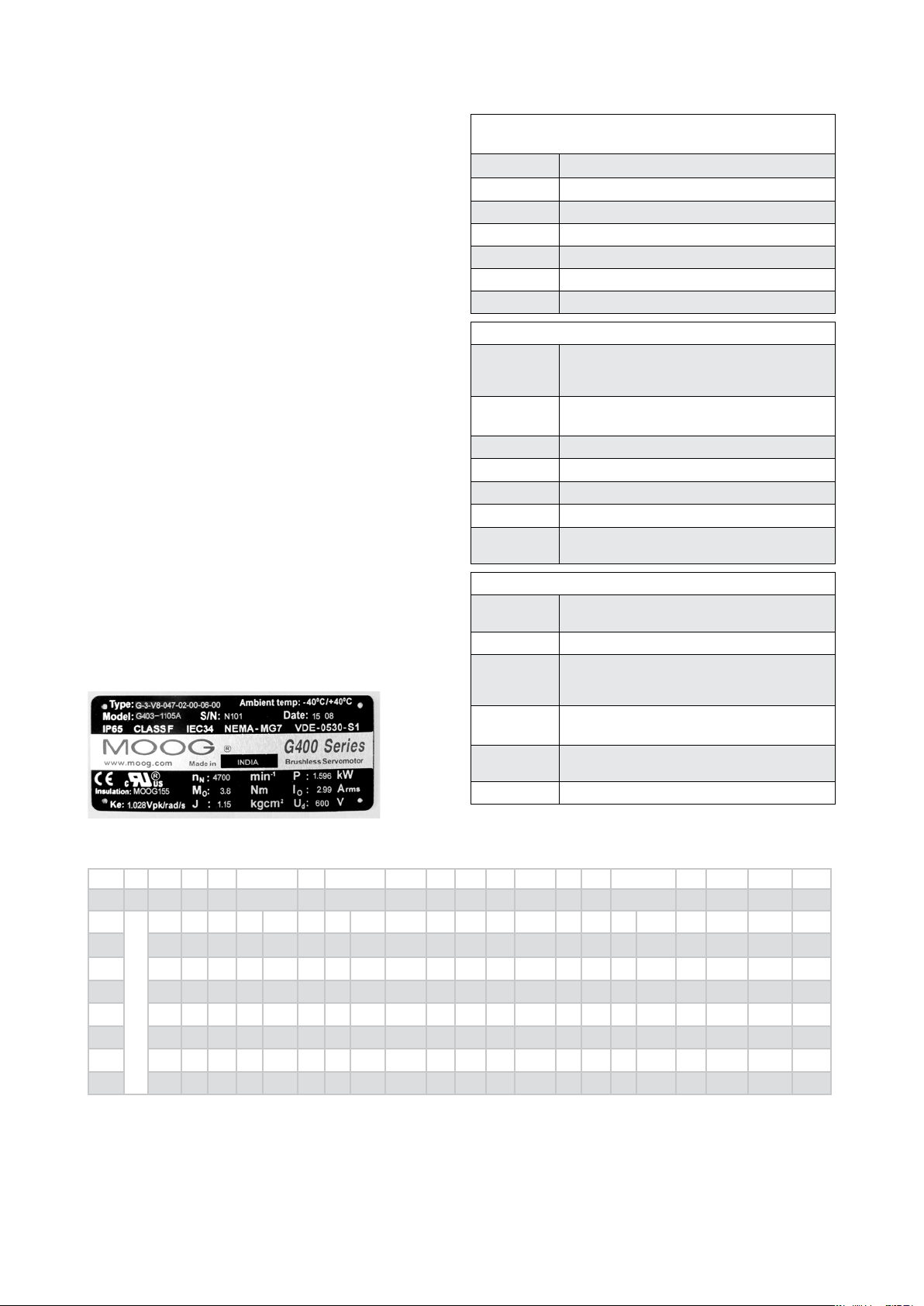
G400 series motor codication
The motor nameplate data are used for the setting of the
servodrive. In case of contact with Moog, identication
data of the motor must be supplied.
Example:
General
Standards
Technical
data
Moog | Installation instructions series G400
Technical data
data are measured at 25°C ambient temperature
n
N
N
P
0
M
0
I
e
K
J
d
U
nominal speed at PN
nominal power (max continuous output power)
continuous stall torque
continuous stall current (at M0)
back emf (voltage constant)
rotor moment of inertia
nominal operatine voltage (bus voltage)
Nameplate data
Type
Ambient
motor type
(Note: for motors built before July 2008 this
may vary)
ambient temperature
temp
Model
S/N
Date
Insulation
Brake
motor model number (ordering number)
serial number
week and year of production
UL approved insulation system
Brake is optional. Data provided refers to
holding torque
Standards
IP65
I.CL.F
IEC34
VDE-0530S1
CE
UL
degree of protection. Motor protected against
jets of water (at shaft with seal option)
motor listed for insulation class F (155°C)
motor fullls IEC34 (Standard denes rating
and performance of rotating electrical machines)
performance measurements are done according
to VDE-0530
conformity certicate will be supplied on
request
motor c-UL Recognized, le number E137630
09/2008
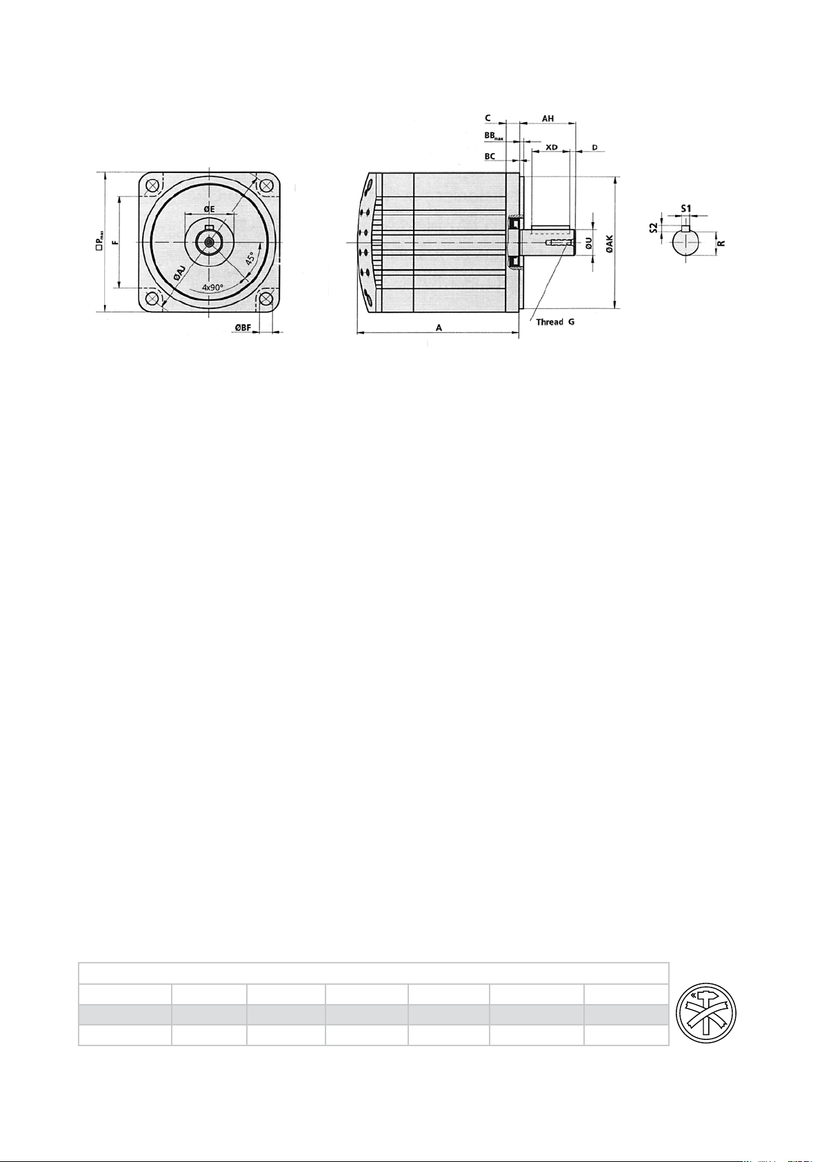
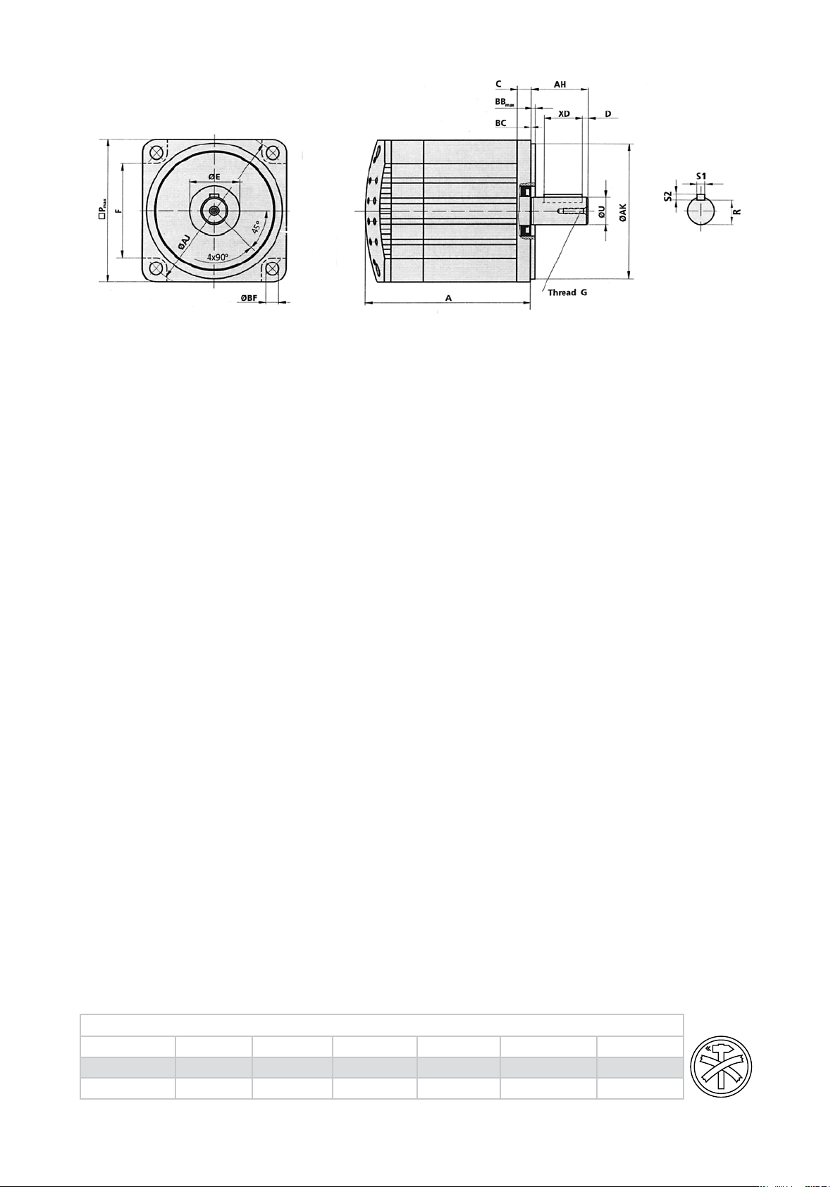
Mounting dimensions for MOOG motors
Type A Pmax C øAJ øAK AH øU BB
mm mm mm mm mm mm mm mm mm mm mm mm mm mm mm Nm
G-1
G-2
G-3
G-4
G-5
G-6
See tables at page 13
ISO
40 7.0 48 18
55 9.0 63 40
70 9.0 75 60
100 9.8 115 95
140 12.2 165 130
190 11.0 215 180
286 286 286 286 286 286 286 286 286 286 286
+0.008
-0.003
+0.011
-0.005
+0.012
-0.007
+0.013
-0.009
+0.014
-0.011
+0.014
-0.011
16 6
20 9
23 11
40 19
50 24
60 32
+0.006
-0.002
+0.010
+0.001
+0.012
+0.001
+0.015
+0.002
+0.015
+0.002
+0.018
+0.002
DIN
A Lengt h of mot or wi thout s haft, pi lot and ma ting con necto r
Pmax Ma ximum w idth of mo tor (end vi ew) exclu ding ter minal ho using, e tc.
C Thick ness of a nge plat e of motor
øAJ Di ameter o f mounti ng bolt ci rcle in an ge of moto r
øAK Diamet er of pilot o n ange of m otor AH Mo untin g surfac e of ange o f
moto r to end of sh aft
øU D iamete r of shaf t extens ion
BB
M aximu m height o f pilot of mo unting ange of mo tor
max
øBF Cl earanc e hole in mo unting ange of mo tor
XD U sable len gth of ke yseat
R Botto m of keysea t to oppos ite side of s haft
All di mension s withou t tolera nce are ac cordin g to DIN ISO 276 8, par t 1, categ ory c.
øBF XD R S1xS2 D BC øE F G H M
max
2.5 3.3 10 4.8 2x2 1.5 0 14
2.5 5.5 14 7.2 3x3 3 0 24
2.5 5.5 16 8.5 4x4 4 0 24
3 9 32 15.5 6x6 4 0 35
3.5 11 40 20 8x7 5 0 47
4 13.5 40 27 10x8 10 0 50
+0.027
- M2.5x8 M3x16 1.3
-0.000
+0.003
- M2.5x8 M5x22 5
-0.000
+0.003
- M2.5x8 M5x22 5
-0.000
+0.039
66.3 M4x16 M8x30 16
-0.000
+0.039
98.8 M4x16 M10x40 30
-0.000
+0.039
128 M4x16 M12x40 38
-0.000
6885 6885 13-1 912 8.8 912 8.8
S1 Widt h of key
S2 Heig ht of key
D Distan ce betw een end of sh aft and k ey
BC Di stance b etwee n mounti ng ange o f motor to s houlde r shaft
(alwa ys=0m m)
øE Di ameter o f hole for sh aft in a nge of mot or
F Wid th of moto r betwe en reces ses for mo unting s crews
G Thread i n motor sh aft
H Recomm ended a nge screw s (kind an d lengt h)
M Tig hteni ng torqu e for ang e screws
2
Page 3
English
Moog | Installation instructions series G400
Mounting
MOOG recommends the use of Hex head screws according to DIN 912 8.8 (see column H in the table on page 2).
The mounting of MOOG motors, especially size 1, 2 and
3 motors, can be eased considerably by the use of a ball
ended, hex key. With these motor sizes, the length of the
screws used for mounting must not exceed 40 mm.
MOOG motors generate heat during normal operation.
Therefore a good heat sink and sufcient ventilation
should be provided when mounting the motor, i.e. the mo-
tor must be tted to a sufciently large metal machine
part. The motors should be protected against contact
with the hot surfaces if necessary.
The motor shaft should be degreased carefully before
mounting a coupling. When using a degreaser (grease
dissolving substance) prevent it from owing into the
bearing as this will destroy the lifetime lubrication. A
clamp coupling or a shrink connection is recommended to
provide a reliable torque transmission.
Caution: The motor can be damaged during mounting by
excessive axial or radial forces applied to the shaft.
The resulting damage to the bearings can reduce the
motor’s life. Excessive axial force on the rotor shaft can
impair the functionality of an optional brake. This leads
either to reduced braking force or brake failure. Therefore excessive pressure and shocks on the front end of
the shaft and the back housing must be avoided under all
circumstances. The impulse of any hammer blow always
exceeds the maximum permissible axial and radial forces.
Electric interfaces
For connection of series G400 MOOG motors, it is best
to use the mating connectors and cable characteristics
indicated in the tables on pages 12 and 13. When using
non MOOG components, the cable specications must be
fullled in every way.
Danger: A rotating motor can generate dangerously high
voltages. Always make sure that there are no exposed
cables.
The pin layouts of the connectors are shown in the following tables. Connection and disconnection of the motors
must be made with the controller switched off. Simply
disabling the controller is not sufcient. During installation, special attention should be paid to the diameter of
the protective earth (PE) conductor, which must be sized
according to legal safety rules.
Caution: Small wire diameters lead to an unacceptable
heating in the cable. This results in power loss to the mo-
tor, especially when the cables are long.
We recommend shielding of power and signal cables. The
shielding should be connected to earth at both ends.
What to do if repairs are required
If a repair of a MOOG motor should prove necessary, all
parts such as gears, toothed wheels, pinions etc. not tted by MOOG, should be removed because MOOG cannot
guarantee correct disassembly. Grease and dirt on the
front ange should also be removed. Moog would appreciate a detailed failure or breakdown report attached to
the delivery paperwork. ”For repair” should be clearly
stated on the delivery note.
09/2008
Maximum permissible axial and radial loads for MOOG motors during installation
Type G-1 G-2 G-3 G-4 G-5 G-6
Axial load*
Radial load*
*: During i nstallat ion. Less lo ad is allowe d when the m otor is rota ting, s. c atalogu e.
75N 150N 150N 300N 400N 500N
300N 500N 500N 1000N 1600N 2000N
3
Page 4
09/2008
Deutsch
Einbauanweisung
Einführung
MOOG bürstenlose Servomotoren der Baureihe G400
sind bauartbedingt wartungsfrei. Die Lager als einzige
verschleißbehaftete Komponente sind mit einer Lebensdauerschmierung ausgerüstet (mind. 20 000 Betriebsstunden bei den angegebenen maximalen Axial- und
Radialkräften). Tritt am Motor dennoch eine Beschädigung auf, so kann diese in der Regel durch MOOG behoben werden. Eine Reparatur durch Fremdpersonal ist
aus Gründen der Produkthaftung ausgeschlossen, da die
geltenden Sicherheitsvorschriften (z.B. VDE-Richtlinien)
und MOOG Qualitätsstandards in der Regel vom Kunden
nicht eingehalten werden können.
Achtung: Eine Zerstörung des Siegellackes an den
Schrauben führt zum Erlöschen jedweden Garantiean-
pruchs.
Empfohlene Antriebe, um den Motor zu steuern, entsprechend UL1004, Par.30.6: MSD Serie, DS2000, von
Moog.
Verpackungsinhalt bei Anlieferung eines MOOG
Motors
Bitte prüfen Sie sofort bei Anlieferung des MOOG Motors den Verpackungsinhalt auf Unversehrtheit und Vollständigkeit des mit Ihnen vereinbarten Lieferumfangs.
Insbesondere die Bereiche des Wellenendes und der
Stecker sollten auf Transportschäden geprüft werden.
Bitte überprüfen Sie anhand der Daten auf dem Typenschild, ob das gelieferte Motormodell mit der Bestellung
übereinstimmt.
Kodifizierung der Serie G400
Die Bewegungstypenschilddaten werden für die Einstellung des Servodrive verwendet. Im Falle des Kontaktes
mit Moog müssen Kennzeichnungsdaten des Motors
bereit gestellt werden.
Beispiel:
Allge mein
Nor men
Moog | Einbauanweisung Baureihe G400
Technische Daten
(Date n werden bei e iner Umge bungste mperatur von 2 5°C gemes sen)
n
N
P
N
M
0
I
0
K
e
J
U
d
nominale Drehzahl (Drehzahl bei PN)
Nennleistung (maximale Dauerleistung)
Dauerstillstandsmoment
Dauerstillstandsstrom (Strom bei M0)
back emf (Spannungskonstante)
Eigenträgheitsmoment des Rotors
Zwischenkreisspannung
Typenschilddaten
Type Motortyp
Ambient
temp
Model Motormodellnummer (Bestellnummer)
S/N Seriennummer
Date Produktionsdatum: Quartal und Jahr
Insulation UL-anerkanntes Isolierungssystem
Brake Bremse ist wahlweise freigestellt. Die bere-
(Anmerkung: bei Motoren, die vor Juli 2008
gebaut wurden, kann dies abweichen)
Umgebungstemperatur
itgestellten Daten beziehen sich auf Holding-
drehkraft.
Normen
IP65
I.CL.F
IEC34
VDE- 0530 S1
CE
UL
Schutzgrad. Motor geschützt gegen Strahlwasser (an der Welle mit Dichtungswahl)
verzeichnet für Isolierungskategorie F (155°C)
Motor erfüllt IEC34 (Standard deniert
Bewertung und Leistung von sich drehenden
elektrischen Maschinen)
Leistungsmessungen sind erfolgt entsprechend
VDE-0530
Übereinstimmungbescheinigung wird geliefert
auf Anfrage
Motor-cUL erkannt, Aktenzeichen E137630
Techni sche
Date n
Einbaumaße für MOOG Motoren
Type A Pmax C øAJ øAK AH øU BB
mm mm mm mm mm mm mm mm mm mm mm mm mm mm mm Nm
G-1
G-2
G-3
G-4
G-5
G-6
ISO
DIN
A Motorlänge
Pmax Flanschquadrat des Motors ohne Stecker etc.
C Dicke der Flanschplatte
øAJ Lochkreisdurchmesser für Flanschschrauben
øAK Zentrierdurchmesser
AH Länge vom Wellenende zur Flanschäche
øU Durchmesser der Welle
BB
Maximale Höhe des Zentrierdurchmessers über
max
der Flanschäche
40 7.0 48 18
55 9.0 63 40
70 9.0 75 60
100 9.8 115 95
140 12.2 165 130
190 11.0 215 180
286 286 286 286 286 286 286 286 286 286 286
siehe Tabellen auf Seite 13
ohne
Welle, Zentrierung, Gegenstecker
Alle A bmessu ngen ohn e Tole ranza ngabe ge mäß DIN ISO 2 768, Teil 1, Ka tegori e c.
+0.008
-0.003
+0.011
-0.005
+0.012
-0.007
+0.013
-0.009
+0.014
-0.011
+0.014
-0.011
16 6
20 9
23 11
40 19
50 24
60 32
+0.006
-0.002
+0.010
+0.001
+0.012
+0.001
+0.015
+0.002
+0.015
+0.002
+0.018
+0.002
øBF Durchmesser der Durchgangslöcher am Motor-
ansch
XD Nutzbare Länge der Paßfedernut
R Abstand vom Boden der Paßfedernut zur ge-
genüberliegenden Seite der Welle
S1 Breite der Paßfeder
S2 Höhe der Paßfeder
D Abstand vom Wellenende zur Paßfeder
øBF XD R S1xS2 D BC øE F G H M
max
2.5 3.3 10 4.8 2x2 1.5 0 14
2.5 5.5 14 7.2 3x3 3 0 24
2.5 5.5 16 8.5 4x4 4 0 24
3 9 32 15.5 6x6 4 0 35
3.5 11 40 20 8x7 5 0 47
4 13.5 40 27 10x8 10 0 50
6885 6885 13-1 912 8.8 912 8.8
BC Abstand zwischen Flanschäche und erster
Wellenschulter auf der Welle (immer =0mm)
øE Durchmesser des Freistichs im Flansch
F Breite des Motors zwischen den Aussparungen
für die Montageschrauben
G Gewinde in der Motorwelle (Typ und Tiefe)
H empfohlene Flanschschrauben (Typ und Länge)
M Anzugsmoment für Flanschschrauben
+0.027
- M2.5x8 M3x16 1.3
-0.000
+0.003
- M2.5x8 M5x22 5
-0.000
+0.003
- M2.5x8 M5x22 5
-0.000
+0.039
66.3 M4x16 M8x30 16
-0.000
+0.039
98.8 M4x16 M10x40 30
-0.000
+0.039
128 M4x16 M12x40 38
-0.000
4
Page 5
Deutsch
Moog | Einbauanweisung Baureihe G400
Montage
MOOG empehlt für die Motorbefestigung die Verwendung von Innensechskantschrauben nach DIN 912
8.8 (siehe in Spalte H der Tabelle auf S. 4). Die Verwendung eines Innensechskantschlüssels mit Kugelkopf
erleichtert speziell bei den Baugrößen 1, 2 und 3 die
Montage wesentlich. Bei diesen Baugrößen dürfen die
verwendeten Schrauben eine Länge von 40 mm nicht
überschreiten. MOOG Motoren können im Betrieb sehr
heiß werden. Bei der Montage ist daher auf eine gute
Wärmeabfuhr zu achten, d.h. der Motor sollte an ein aus-
reichend massives Metall-Maschinenteil angeanscht
werden. Weiterhin muss eine ausreichende Konvektion
sichergestellt sein. Im Einzelfall sind die Motoren gegen
Berührung zu sichern, da Verbrennungsgefahr besteht.
Vor dem Anbringen einer Kupplung auf die Motorwelle
sollte diese gründlich entfettet werden. Bei Verwendung
eines Entfetters (fettlösenden Mittels) ist darauf zu
achten, dass dieser nicht in das Lager gelangt, da sonst
für dieses die Lebensdauerschmierung nicht mehr gewährleistet ist. Für eine sichere Momentenübertragung
empfehlen wir die Verwendung einer Klemmkupplung
bzw. einer Schrumpfverbindung.
Vorsicht: Durch unzulässig hohe Axial- bzw. Radialkräfte
an der Welle kann der Motor bei der Montage beschädigt
werden.
schaften, die in den Tabellen auf den Seiten 12 und 13
angezeigt werden, zu verwenden. Wenn man nicht MOOG
Bestandteile verwendet, müssen die Kabelspezikationen auf jede Art erfüllt werden.
Achtung: ein sich drehender Motor kann gefährliche
Hochspannung abgeben. Deshalb ist stets darauf zu
achten, dass keine offenen Kabel vorhanden sind.
Die Pin-Belegungen der Stecker entsprechen den
folgenden Schemata. Die Montage und Demontage der
Steckverbinder muss stets bei ausgeschaltetem Controller erfolgen. Das Deaktivieren des Controllers allein ist
dafür nicht ausreichend. Bei der Installation ist insbesondere auf einen den gültigen Sicherheitsrichtlinien
entsprechenden Schutzleiterquerschnitt zu achten.
Achtung: kleine Leiterquerschnitte führen zu einer
unzulässig starken Erwärmung des Kabels. Dies hat, besonders bei langen Zuleitungen, Leistungsverluste des
Motors zur Folge.
Bei der Installation der Zuleitungen empfehlen wir eine
Schirmung der Leistungs- und Signalkabel. Dabei ist die
Schirmung beidseitig auf Massepotential zu legen.
Verhalten im Reparaturfall
09/2008
Die möglicherweise auftretenden Lagerbeschädigungen
reduzieren die Motorlebensdauer. Ein gewaltsames
Verschieben der Rotorwelle kann die Funktion der
optionalen Bremse so beeinträchtigen, dass diese keine
oder nur eine reduzierte Bremswirkung besitzt. Aus
diesem Grund sind übermäßiger Druck und Stöße auf das
vordere Wellenende bzw. den hinteren Gehäusedeckel
unter allen Umständen zu vermeiden. Durch den mit Hammerschlägen verbundenen Impuls werden die zulässigen
Axial- bzw. Radialkräfte in jedem Fall überschritten.
Sollte eine Reparatur eines MOOG Motors notwendig
sein, so sind alle nicht von MOOG angebrachten Anbauteile wie Getriebe, Zahnräder, Ritzel etc. zu demontieren,
da MOOG die korrekte vorschriftsmäßige Demontage
nicht garantieren kann. Evtl. vorhandene Verschmutzungen am vorderen Lagerschild des Motors sollten
ebenfalls entfernt werden. Nach Möglichkeit ist den
Lieferpapieren eine detaillierte Ausfallbeschreibung
oder ein Fehlerbefund beizufügen. Auf dem Lieferschein
ist deutlich sichtbar der Vermerk „ Zur Reparatur“ anzubringen. Der Motor ist stoßsicher zu verpacken, so dass
Elektrische Schnittstellen
Transportbeschädigungen vermieden werden.
Zum Anschluss der Motoren der Reihe G400 MOOG ist
es am besten, die Gegenstecker und die Kabeleigen-
Maximal zulässige Axial- und Radialkräfte für MOOG Motoren während der Montage
Typ G-1 G-2 G-3 G-4 G-5 G-6
Axialkraft*
Radialkraft*
*: Wäh rend des Ei nbaus. Bei rotierendem M otor gelte n geringere Krä fte, s. Ka talog.
75N 150N 150N 300N 400N 500N
300N 500N 500N 1000N 1600N 2000N
5
Page 6

09/2008
Italiano
Moog | Istruzioni di installazione serie G400
Istruzioni di installazione
Introduzione
I servomotori brushless MOOG serie G400 sono esenti
da manutenzione. La longevità dei motori è limitata
solamente dalla durata dei cuscinetti, che sono lubricati
a vita (Per un minimo funzionamento di 20000 ore con
carico assiale e radiale raccomandato). Per questioni
di responsabilità di prodotto qualsivoglia guasto deve
essere riparato esclusivamente da MOOG, personale
non MOOG potrebbe non essere in grado di rispettare
le norme di sicurezza (es. direttive VDE) e gli standard
qualitativi MOOG.
Attenzione: La rimozione dei sigilli delle viti invalida la
garanzia.
Servoazionamenti consigliati, secondo la UL1004,
Par. 30.6: MSD e DS2000 di Moog.
Spedizione
Vericare che i motori ricevuti non abbiano subito danni
durante il trasporto specialmente nell’area dell’albero
e dei connettori. Confrontare il modello motore della
targhetta identicativa con quanto ordinato.
Codifica dei motori serie G400
Dati tecnici
(dati rilevati con temperatura ambiente di 25°C)
n
N
P
N
M
0
I
0
K
e
J momento di inerzia del rotore
U
d
velocità nominale con PN
potenza nominale (è la massima potenza con-
tinuativa)
coppia continuativa allo stallo
corrente continuativa (con M0)
back emf (costante di tensione)
tensione nominale di lavoro (tensione di bus)
Dati di Targa
Type modello motore
Ambient
temp
Model per la descrizione fare riferimento al catalogo
S/N numero di serie
Date settimana e anno di produzione
Insulation sistema di isolamento approvato UL
Brake coppia di frenatura del freno opzionale
(Nota: per motori costruiti prima di luglio 2008
potrebbe variare)
temperatura ambiente
motori
I dati di targa del motore sono utilizzati per la messa
a punto del servoconvertitore. Se si contatta Moog, si
prega di fornire i dati identicativi del motore.
Esempio:
Gene rale
Nor mative
Dati t ecnici
IP65
I.CL.F
IEC34
VDE- 0530 S1
CE
UL
Dimensioni di montaggio dei motori
Type A Pmax C øAJ øAK AH øU BB
mm mm mm mm mm mm mm mm mm mm mm mm mm mm mm Nm
G-1
G-2
G-3
G-4
G-5
G-6
ISO
DIN
A Lunghezza motore, escluso: albero, angia di
ssaggio e parte volante dei connettori
Pmax Massima larghezza motore (vista lato albero),
escluso coperchio posteriore
C Spessore della angia di ssaggio del motore
øAJ Diametro del giro fori di ssaggiodel motore
øAK Diametro della angia di centraggio
AH Lunghezza dell’albero motore
øU Diametro dell’albero motore
BB
Rilievo della angia di centraggio rispetto alla
max
faccia della angia di montaggio del motore
40 7.0 48 18
55 9.0 63 40
70 9.0 75 60
100 9.8 115 95
140 12.2 165 130
190 11.0 215 180
286 286 286 286 286 286 286 286 286 286 286
Vedere tabelle a pagina 13
Le dim ensioni p er le qual i non sono i ndicat e tollera nze sono s econdo D IN ISO 2768 , parte 1 , catego ria c.
+0.008
-0.003
+0.011
-0.005
+0.012
-0.007
+0.013
-0.009
+0.014
-0.011
+0.014
-0.011
16 6
20 9
23 11
40 19
50 24
60 32
+0.006
-0.002
+0.010
+0.001
+0.012
+0.001
+0.015
+0.002
+0.015
+0.002
+0.018
+0.002
øBF Diametro dei fori di ssaggio del motore
XD Lunghezza della linguetta
R Altezza dal fondo della sede della linguetta al lato
opposto dell’albero motore
S1 Larghezza della linguetta
S2 Spessore della linguetta
D Distanza tra l’estremità della linguetta e
l’estremità dell’albero motore
BC Distanza tra lo spallamento dell’albero e la angia
di montaggio del motore (sempre = 0mm)
øBF XD R S1xS2 D BC øE F G H M
max
2.5 3.3 10 4.8 2x2 1.5 0 14
2.5 5.5 14 7.2 3x3 3 0 24
2.5 5.5 16 8.5 4x4 4 0 24
3 9 32 15.5 6x6 4 0 35
3.5 11 40 20 8x7 5 0 47
4 13.5 40 27 10x8 10 0 50
6885 6885 13-1 912 8.8 912 8.8
Normative
grado di protezione: protetto contro spruzzi
d’acqua (all’albero con anello paraolio opzionale)
isolamento in classe F (155°C) I materiali utiliz-
zati sono in classe H (180°C)
motore secondo la norma IEC34 (classicazione
e prestazioni delle macchine elettriche rotanti)
misura delle prestazioni secondo la norma
VDE-0530
il certicato di conformità viene fornito su
richiesta
motore riconosciuto c-UL, pratica UL numero
E137630
+0.027
- M2.5x8 M3x16 1.3
-0.000
+0.003
- M2.5x8 M5x22 5
-0.000
+0.003
- M2.5x8 M5x22 5
-0.000
+0.039
66.3 M4x16 M8x30 16
-0.000
+0.039
98.8 M4x16 M10x40 30
-0.000
+0.039
128 M4x16 M12x40 38
-0.000
øE Diametro del foro di passaggio dell’albero attra-
verso la angia di montaggio del motore
F Larghezza del motore tra le asole per le viti di
ssaggio del motore
G Foro lettato
H Tipo e lunghezza raccomandata per le viti di
ssaggio del motore
M Coppia di serraggio delle viti di ssaggio del
motore
6
Page 7

Italiano
Moog | Istruzioni di installazione serie G400
Montaggio
E’ raccomandato l’impiego di bulloni con testa cilindrica
con esagono incassato secondo DIN 912 8.8 (colonna H
tabella pagina 6). Per i motori taglia 1, 2 e 3 la massima
lunghezza delle viti di ssaggio è 40 mm). I motori elett-
rici durante il loro normale funzionamento generano ca-
lore. Il motore deve essere installato su angia metallica
con supercie tale da garantire una buona dissipazione
del calore. Il motore deve essere sufcientemente ventilato e deve essere protetto dal contatto con superci
a temperatura elevata. Il grasso di protezione dell’albero
motore deve essere rimosso prima del montaggio.
Durante l’operazione di pulizia evitare che il solvente
contamini il grasso del cuscinetto compromettendone la
lubricazione a vita. Per ottenere un’efciente trasmissione della coppia è raccomandato l’impiego di calettatori, conici o a morsetto.
Attenzione: Durante il montaggio non danneggiare il
motore applicando eccessivo carico radiale e assiale
all’albero motore.
Il danneggiamento dei cuscinetti può comportare la riduzione della vita del motore. Un eccessivo carico assiale
dell’albero motore può compromettere il funzionamento
del freno opzionale riducendone la coppia frenante o causandone la rottura. Evitare in ogni caso che il coperchio
posteriore e l’albero motore siano sottoposti ad urti o
eccessiva pressione. Durante il montaggio non utilizzare
il martello perché ogni colpo produce sempre un urto che
supera il massimo carico assiale e radiale ammissibile.
Connessioni elettriche per i motori
Per il collegamento elettrico di serie G400 MOOG si
consiglia di utilizzare i connettori e le caratteristiche di
accoppiamento del cavo indicate nelle tabelle pagina 12 e
13. Usando componenti non MOOG, le speciche del cavo
devono essere rispettate in ogni caso.
Attenzione: il motore in rotazione può generare correnti
elettriche pericolose. Accertarsi che non vi siano cavi
esposti.
Le tabelle a pagina 12 e 13 illustrano la disposizione dei
contatti dei connettori. Il collegamento e lo scollegamento dei motori deve sempre avvenire con il convertitore
di potenza spento. Non è sufciente la semplice disabilitazione del convertitore di potenza. Nell’installazione
il conduttore di terra (PE) deve essere dimensionato
secondo le regole di sicurezza vigenti.
Attenzione: li elettrici con diametro eccessivamente
ridotto comportano un surriscaldamento inaccettabile
del cavo che, specialmente nel caso di collegamenti
lunghi, comporta una perdita di potenza del motore.
E’ raccomandata la schermatura sia dei cavi di potenza
che di quelli di segnale. Lo schermo deve essere collegato
ad entrambi i capi.
Cosa fare nel caso sia richiesta la riparazione di un
motore
Nel caso sia necessario eseguire la riparazione di un
motore MOOG, tutti i componenti che non fanno parte
del motore es. ruote dentate, pignoni ecc., devono essere
tolti, dato che MOOG non può garantirne la corretta
rimozione. Anche grasso e sporco devono essere asportati. E’ utile allegare ai documenti di spedizione una nota
accurata sulla ragione del difetto. La dicitura “In ripara-
zione“ deve essere indicata chiaramente sui documenti
di spedizione. Il motore deve essere imballato in modo da
evitare danni di trasporto.
09/2008
Massimo carico assiale e radiale dei motori ammesso durante l’installazione
Taglia del motore G-1 G-2 G-3 G-4 G-5 G-6
Carico assiale*
Carico radiale*
*: All ’installazione . Vede re il catalo go motori per inf ormazio ni sul cari co ammesso in rotazio ne, che è inf eriore. .
75N 150N 150N 300N 400N 500N
300N 500N 500N 1000N 1600N 2000N
7
Page 8

09/2008
Français
Moog | Instruction d’installation séries G400
Instruction d’installation
Introduction
Le terme sans balais implique que les moteurs MOOG
de la série G400 ne nécessitent pas de maintenance. La
longévité des moteurs n’est limitée que par la durée de
vie des roulements lubriés à vie (minimum de 20,000
opérations heures en respectant les recommandations
de charges axiales et radiales). En raison de la abilité
du produit les dommages causés au moteur doivent être
réparés par MOOG, le personnel non MOOG peut ne pas
être en mesure de remplir les conditions de sécurités
imposé par la réglementation (ex. normes VDE).
Attention: La destruction du joint de peinture sur les vis
entraîne l’annulation de la garantie.
Commandes recommandées à employer pour commander
le moteur, selon UL1004, Par.30.6 : Série de MSD série,
DS2000, par Moog.
Expédition
Vérier si le moteur reçu n‘a pas subit de dommage durant le transport , et plus spécialement du côté de l‘arbre
de transmission, et du connecteur. Vérier également
que le numéro de modèle du moteur expédié , correspond
bien à celui commandé.
Codication de moteur de série G400
Les données de plaque signalétique de moteur sont
employées pour l‘arrangement du moteurs. En cas de
contact avec Moog, des descriptions du moteur doivent
être fournies.
Exemple:
Géné ralités
Nor mes
Donn ées tech niqu es
(des do nnées son t mesurée s à la température 25° C ambiante):
n
N
P
N
M
0
I
0
K
e
J
U
d
vitesse nominale (vitesse à PN)
puissance nominale (puissance continue maximum)
couple continue à vitesse nulle
corrente continuativa (con M0)
back emf (constante de tension)
inertie du rotor
tension du bus
Données de plaque signalétique
Données techniques
Type
Ambient
temp
Model
S/N
Date
Insulation
Brake
modèle moteur
(Note: pour des moteurs construits avant juillet
2008 ceci peut varier)
température ambiante
numéro de type de moteur (numéro de commande)
numéro de série
semaine et année de production
Système approuvé d‘isolation d‘UL
Le frein est facultatif. Les données fournies se
rapportent au couple de possession
Normes
IP65
I.CL.F
IEC34
VDE- 0530 S1
CE
UL
degré de protection. Moteur protégé contre des
gicleurs du moteur de l‘eau (à l‘axe avec l‘option de
joint)
énuméré pour la classe F d‘isolation (155°C)
le moteur accomplit IEC34 (la norme dénit
l‘estimation et l‘exécution de machines électriques
tournantes)
des mesures d‘exécution sont faites selon VDE0530
le certicat de conformité sera fourni sur demande
c-UL de moteur identiée, nombre de dossier
E137630
Dimensions de montage pour les moteurs MOOG
Type A Pmax C øAJ øAK AH øU BB
mm mm mm mm mm mm mm mm mm mm mm mm mm mm mm Nm
G-1
G-2
G-3
G-4
G-5
G-6
ISO
DIN
A Largeur maximum du moteur (vue arrière) exclu ant les capots de connecteur
Pmax Longueur du moteur sans arbre et sans con
necteurs etc
C Epaisseur bride avant du moteur
øAJ Diamètre de montage des vis de la bride du
moteur
øAK Diamètre de centrage de la bride du moteur
AH Longueur de l’arbre moteur
40 7.0 48 18
55 9.0 63 40
70 9.0 75 60
100 9.8 115 95
140 12.2 165 130
190 11.0 215 180
286 286 286 286 286 286 286 286 286 286 286
Voir les tableaux à la page 13
Toutes l es dimen sions san s toléra nce selon D IN ISO 2768 , chapi tre 1, caté gorie c.
+0.008
-0.003
+0.011
-0.005
+0.012
-0.007
+0.013
-0.009
+0.014
-0.011
+0.014
-0.011
16 6
20 9
23 11
40 19
50 24
60 32
+0.006
-0.002
+0.010
+0.001
+0.012
+0.001
+0.015
+0.002
+0.015
+0.002
+0.018
+0.002
øU
BB
max
øBF Diamètre des trous de xations
XD Longueur de clavette
R Fond du logement de clavette
S1 Largeur de la clavette
S2 Hauteur de la clavette
D Distance bout arbre clavette
BC Distance entre la bride et l’épaulement de l’arbre
(toujours = 0 mm)
max
2.5 3.3 10 4.8 2x2 1.5 0 14
2.5 5.5 14 7.2 3x3 3 0 24
2.5 5.5 16 8.5 4x4 4 0 24
3 9 32 15.5 6x6 4 0 35
3.5 11 40 20 8x7 5 0 47
4 13.5 40 27 10x8 10 0 50
Diamètre de l’arbre
Hauteur maximum de centrage
øBF XD R S1xS2 D BC øE F G H M
+0.027
- M2.5x8 M3x16 1.3
-0.000
+0.003
- M2.5x8 M5x22 5
-0.000
+0.003
- M2.5x8 M5x22 5
-0.000
+0.039
66.3 M4x16 M8x30 16
-0.000
+0.039
98.8 M4x16 M10x40 30
-0.000
+0.039
128 M4x16 M12x40 38
-0.000
6885 6885 13-1 912 8.8 912 8.8
øE Diamètre du logement pour l’arbre dans la bride
F Largeur du moteur entre les rainures de vis de
montages
G Taraudage arbre moteur (type et longueur)
H Vis recommandées pour la xation (type et
longueur)
M Couple de serrage des vis de xations
8
Page 9

Français
Moog | Instruction d’installation séries G400
Montage
MOOG recommande l’utilisation de six vis à tête hexago-
nale conforme à la norme DIN 912 8.8 (voir colonne H du
tableau à page 8). Le montage du moteur, plus précisé-
ment les tailles 1, 2 et 3, peut être facilité par l’utilisation
d’une clé hexagonale à tette sphérique. Pour cette
dimension de moteur, la longueur des vis de montage ne
doit pas exeder 40 mm. En fonctionnement normal les
moteurs MOOG génère de la chaleur. Par conséquence
veiller à installer le moteur en association avec un radiateur et/ou un bon système de ventilation, par exemple
le moteur doit être xé sur une partie métallique de la
machine sufsamment large. Le moteur doit être protégé
des contacts avec les parties chaudes. L’arbre du moteur doit être dégraissé avant montage. Si vous utilisez
un produit dégraissant veillez à protéger le moteur de
la diffusion du produit sur les roulements internes, en
effet ceci détruirait la lubrication à vie des roulements.
Un accouplement par arbre pincé ou claveté est recommandé pour une bonne transmission de couple.
Attention: le moteur peut être endommagé au montage
par l’application de charge radiales ou axiales exessivent
sur l’arbre.
Les dommages résultants sur les roulement s peuvent
réduire la durée de vie du moteur. Les forces axiale
excessive peuvent endommagé le frein en option. Ce
dommage peut amener une réduction de l’effort de freinage voir un défaut total du frein. Par conséquence les
pressions et chocs excessifs sur l’avant de l’arbre sont
prescrites dans tous les cas. L’utilisation d’un marteau
exedera dans tous les cas les charges maximales autorisées.
Interfaces électriques
Pour le raccordement des moteurs de la série G400
MOOG, il est le meilleur d‘employer les connecteurs et
les caractéristiques de accouplement de câble indiquées
dans les tables aux pages 12 et 13. En employant non
des composants de MOOG, les caractéristiques de câble
doivent être accomplies de chaque manière.
Attention: un moteur en rotation génère des tensions
létales. Assurez vous toujours qu’aucun câble n’est
dénudé.
La description des broches des connecteurs est donnée
dans le tableau qui suit. La connexion et la déconnexion
du moteur doit être effectué le variateur hors tension.
Le fait de le devalider n’est pas sufsant. Au cours de
l’installation, une attention particulière doit être portée
au diamètre des câbles de terre (PE), ils doivent être
dimensionnés selon les normes légales de sécurité en
vigueur.
Attention: les faibles sections de câbles induisent des
effets thermiques inacceptables. Cela conduit à des
pertes de puissances dans le moteur particulièrement
quand les câbles sont longs.
Nous recommandons le blindage des câbles puissances et
signal. Le blindage doit être connecté à la terre à chaque
extrémité.
Que faire en cas de réparation
Si la réparation d’un moteur sans balais MOOG s’avère nécessaire, tous les éléments comme les réducteurs, roues
dentés, pignons etc. hors fourniture MOOG, doivent être
enlevés, MOOG ne garantit pas un désassemblage correct. La graisse et la saleté en face avant doit aussi être
enlevées. Nous apprécierions un rapport de défaut ou
d’arrêt détaillé, joint au document de livraison. La mention “Pour réparation“ doit être clairement indiqué sur les
bordereaux. Le moteur doit être correctement emballé
pour éviter les dommages subit durant le transport.
09/2008
Charge axiale et radiale maximale autorisées sur les servomoteurs MOOG
Taille de moteur G-1 G-2 G-3 G-4 G-5 G-6
charge axiale*
charge radiale*
*: A l’arret. En ro tation les e ffort s applicab les sont in férieure s, c.f. catalogu e..
75N 150N 150N 300N 400N 500N
300N 500N 500N 1000N 1600N 2000N
9
Page 10

09/2008
Español
Instrucciones de montaje
Introducción
Los servomotores MOOG de la serie G400 no necesitan
mantenimiento debido a que no tienen escobillas. La vida
de los motores está limitada tan solo por la duración de
los rodamientos, los cuales ya vienen lubricados (Para
un mínimo de 20,000 horas de funcionamiento con la
máxima carga radial y axial recomendada). Por razones
de seguridad cualquier motor dañado deberá de ser
reparado por MOOG. Otro personal que no pertenezca a
MOOG no dispone de la normativa de calidad y seguridad
que MOOG aplica a sus productos.
Atención: la destrucción de los sellos de pintura en los
tornillos anulará la garantía.
Impulsiones recomendadas que se utilizarán para controlar el motor, según UL1004, Par.30.6: serie de MSD
serie, DS2000, por Moog.
Envío
Vericar que el motor recibido no ha recibido daños en el
transporte, especialmente en la zona del eje y los conectores. Comprobar que el modelo pedido corresponde al
mismo que se describe en la placa de identicación.
Codificación del motor de serie G400
Los datos de la placa de identicación del motor se utilizan para el ajuste del servomotores. En caso de contacto
con Moog, los datos de identicación del motor deben
ser suministrados.
Ejamplo:
Gene ral
Està ndares
Dato s técnico s
Dimensiones para el mantaje de servomotores MOOG
Type A Pmax C øAJ øAK AH øU BB
mm mm mm mm mm mm mm mm mm mm mm mm mm mm mm Nm
G-1
G-2
G-3
G-4
G-5
G-6
ISO
DIN
A Longitud del motor sin eje, guía para montaje ni
conectores
Pmax Anchura máxima del motor (alzado) excluyendo
conectores etc.
C Espesor de la brida de montaje del motor
øAJ Distancia entre agujeros en la brida de montaje
øAK Diámetro de la guía en la brida del motor
AH Distancia entre la brida de montaje y el eje
øU Diámetro del eje de salida
BB
Altura máxima de la guía de montaje del motor
max
40 7.0 48 18
55 9.0 63 40
70 9.0 75 60
100 9.8 115 95
140 12.2 165 130
190 11.0 215 180
286 286 286 286 286 286 286 286 286 286 286
Vea las tablas en la página 13
Todas las d imensi ones sin to leranc ia están d e acuerd o a la norma D IN ISO 2768 , part e 1, catego ría c.
+0.008
-0.003
+0.011
-0.005
+0.012
-0.007
+0.013
-0.009
+0.014
-0.011
+0.014
-0.011
16 6
20 9
23 11
40 19
50 24
60 32
+0.006
-0.002
+0.010
+0.001
+0.012
+0.001
+0.015
+0.002
+0.015
+0.002
+0.018
+0.002
øBF Diámetro de los agujeros para montaje con
tornillos
XD Longitud del chavetero
R Distancia de la base del chavetero al eje
S1 Anchura de la chaveta
S2 Altura de la chaveta
D Distancia de la chaveta al nal del eje
BC Distancia entre la brida de montaje del motor y el
apoyo del eje (siempre =0mm)
øE Diámetro del agujero para el eje en la brida
øBF XD R S1xS2 D BC øE F G H M
max
2.5 3.3 10 4.8 2x2 1.5 0 14
2.5 5.5 14 7.2 3x3 3 0 24
2.5 5.5 16 8.5 4x4 4 0 24
3 9 32 15.5 6x6 4 0 35
3.5 11 40 20 8x7 5 0 47
4 13.5 40 27 10x8 10 0 50
n
P
M
I
K
J momento de inercia del rotor
U
Type tipo modelo
Ambient
temp
Model número de modelo del motor
S/N número de serie
Date semana y año de producción
Insulation Sistema aprobado del aislamiento de la UL
Brake El freno es opcional. Los datos proporcionados
IP65
I.CL.F
IEC34
VDE- 0530 S1
CE
UL
6885 6885 13-1 912 8.8 912 8.8
Moog | Instrucciones de montaje serie G400
Datos técnicos
(los da tos se han obtenid o a una temperat ura ambie nte de 25°C ):
N
N
velocidad nominal (velocidad a PN)
potencia nominal (potencia máxima en con-
tinuo)
0
0
e
d
momento ecaz en operación continua
corriente ecaz en operación continua
back emf (constante de voltaje)
tensión del bus
Datos de la placa de identicación
(Nota: para los motores construidos antes del
julio de 2008 esto puede variar)
temperatura ambiente
(número el ordenar)
reeren al
esfuerzo de torsión de la tenencia
Estàndares
grado de protección. Motor protegido contra
los jets del motor del agua (en el eje con la
opción del sello)
enumerado para la clase F del aislamiento
(155°C)
el motor satisface IEC34 (el estándar dene el
grado y el funcionamiento de máquinas eléctricas giratorias)
las medidas de funcionamiento se hacen según
VDE-0530
el certicado de la conformidad será suminis-
trado a petición
c-UL reconocida, número de archivo E137630
del motor
+0.027
- M2.5x8 M3x16 1.3
-0.000
+0.003
- M2.5x8 M5x22 5
-0.000
+0.003
- M2.5x8 M5x22 5
-0.000
+0.039
66.3 M4x16 M8x30 16
-0.000
+0.039
98.8 M4x16 M10x40 30
-0.000
+0.039
128 M4x16 M12x40 38
-0.000
F Distancia entre alojamientos para las cabezas de
los tornillos de montaje del motor
G Rosca en el eje del motor
H Tornillos recomendados para el montaje (tipo y
tamaño)
M Par de apriete de los tornillos
10
Page 11

Español
Moog | Instrucciones de montaje serie G400
Instalación
MOOG recomienda el uso de tornillos con cabeza “Allen”
de acuerdo con la norma DIN 912 8.8 (ver columna H in
la tabla paginà 10). El montaje de los motores MOOG,
especialmente de las series 1, 2 y 3, se facilitará considerablemente si se utilizan llaves hexagonales terminados
en bola. Con estos motores la longitud del tornillo no será
superior a 40 mm. Los motores MOOG producen calor
durante su funcionamiento normal. Por esta razón es
conveniente montarlos en zonas ventiladas y con buena
disipación, p.ej. en un soporte metálico sucientemente
grande de la máquina. En caso de ser necesario, los
motores estarán protegidos para evitar su contacto con
supercies calientes. Antes de montar un acoplamiento
sería conveniente desengrasar el eje.Cuando se utilice
un desengrasante (disolvente de grasas, etc.) cuidar de
que este no se introduzca en el rodamiento, ya que podría
desaparecer la lubricación del mismo. Para disponer de
una transmisión ecaz del par se recomienda utilizar
acoplamientos especiales sujetos con apriete adecuado o
ajustados al eje por calor.
Atención: el motor se puede dañar si se aplica una fuerza
axial o radial excesiva durante su instalación.
Conexiones eléctricas
Para la conexión de los motores de la serie G400 MOOG,
es el mejor utilizar los conectadores y las características
de acoplamiento del cable indicadas en las tablas paginàs
12 y 13. Al usar no componentes de MOOG, las especicaciones del cable se deben satisfacer de cada manera.
El conexionado de los contactos del conector se describe
en las tablas siguientes. La conexión y desconexión del
motor se debe de realizar con el regulador apagado. No es
suciente con que el motor esté deshabilitado. Durante
la instalación se debe de prestar especial atención al
diámetro del cable de tierra (PE), el cual debe ser correctamente dimensionado de acuerdo a las normas de
seguridad vigentes.
Atención: Un diámetro de cable insuficiente provocará
un calentamiento inaceptable del mismo. Esto se traduce
en una reducción del rendimiento del motor, especialmente cuando los cables son largos.
Recomendamos el apantallamiento de los cables de
potencia y resolver. La pantalla se conectará a tierra por
ambos lados.
Instrucciones cuando se necesita una reparación.
Si un motor MOOG necesita una reparación, se deben
desmontar del mismo todos los accesorios que no hayan
sido montados por MOOG, tales como reductoras, poleas
dentadas, piñones, etc., ya que MOOG no puede garantizar su correcta manipulación. Se debe limpiar la brida
delantera de suciedad y grasa. MOOG agradecerá una
detallada descripción del problema en el albarán de envío.
Se debe leer claramente en el albarán el mensaje “Para
reparar”. El motor deberá ser correctamente embalado
para evitar daños en el transporte.
09/2008
Atención: Un motor en funcionamiento puede generar
tensiones muy elevadas que serán peligrosas. Asegúrese
de que no hay conductores o parte de ellos sin aisla-
miento.
Carga máxima axial y radial permitidas en el montaje de un servomotor MOOG
Tamaño motor G-1 G-2 G-3 G-4 G-5 G-6
Fuerza axial*
Fuerza radial*
*: Durant e su instala ción. Cua ndo el motor trabaja , estas car gas son inferio res,ver cat álogo.
75N 150N 150N 300N 400N 500N
300N 500N 500N 1000N 1600N 2000N
11
Page 12

D
E
EN
F
I
Shield
Data-
REFSIN
SIN+
REFCOS
Data+
COS+
GND
Us
Temperature
sensor
Incremental sine (-)
Incremental sine (+)
Data asynchronous serial line
Hiperface(-)
Incremental cosine (-)
Data asynchronous serial line
Hiperface(+)
Incremental cosine (+)
Encoder supply (Vcc+)
Encoder supply (GND)
Inner shield
Vacant
Vacant
Vacant
Vacant
Vacant
Vacant
3
4
8
7
15
6
14
5
9
10
16
11
13
17
12
2
1
17
16
15
14
13
12
11
10
9
8
MOTOR
1
3
4
7
2
6
5
TEMPERATURE
SENSOR
ENCODER
Encoder supply (GND)
Encoder supply (Vcc+)
Inner shield
Incremental signal B (-)
Incremental signal A (-)
Commutation track T (-)
Commutation track S (+)
Zero signal (-)
Incremental signal A (+)
Zero signal (+)
Incremental signal B (+)
Commutation track S (-)
Commutation track R (+)
Commutation track T (+)
Commutation track R (-)
R
Us
S
GND
Shield
B+
Z+
R
T
B-
Z-
A+
A-
T
S
3
4
8
7
15
6
14
5
9
10
16
11
13
17
12
2
1
17
16
15
14
13
12
11
10
9
8
MOTOR
1
3
4
7
2
6
5
sensor
Temperature
TEMPERATURE
SENSOR
ENCODER
Encoder supply (GND)
Encoder supply (Vcc+)
Clock synchronous serial line (+)
Inner shield
Incremental cosine (+)
Data synchronous serial line EnDat (+)
Supply feedback (GND)
Up sensor
0V sensor
Up
CLOCK
0V (Un)
Shield
B+
DATA
Supply feedback (+)
CLOCK
Clock synchronous serial line (-)
Incremental cosine (-)
B-
Data synchronous serial line EnDat (-)
DATA
Incremental sine (+)
A+
Incremental sine (-)
A-
3
4
8
7
15
6
14
5
9
10
16
11
13
17
12
2
1
17
16
15
14
13
12
11
10
9
8
MOTOR
1
3
4
7
2
6
5
Vacant
Vacant
sensor
Temperature
ENCODER
TEMPERATURE
SENSOR
Encoder supply (GND)
Encoder supply (Vcc+)
Inner shield
Incremental cosine (+)
Supply feedback (GND)
Up sensor
R-
0V sensor
Up
D-
0V (Un)
Shield
B+
C+
R+
Supply feedback (+)
D+
Incremental cosine (-)
B-
Absolute sine (-)
C-
Incremental sine (+)
A+
Incremental sine (-)
A-
Absolute sine (+)
Absolut cosine (-)
Absolut cosine (+)
Zero track (-)
Zero track (+)
3
4
8
7
15
6
14
5
9
10
16
11
13
17
12
2
1
17
16
15
14
13
12
11
10
9
8
MOTOR
1
3
4
7
2
6
5
sensor
Temperature
TEMPERATURE
SENSOR
ENCODER
Wiring Schematics: Encoder Signal Connections
Verdrahtungsdiagramme: Anschlussbelegung Encoder
Schemi di collegamento: Connessioni di segnale encoder
Schémas de câblage
Diagramas esquemáticos del cableado
Moog | Installation instructions G400 series
Wiring of signal cable and mating connector
(contact side of motor connector = rear view of
standard motor)
Anschlussbelegung Signalkabel und –gegen-
stecker (Draufsicht auf Motoranschdose,
Gegenstecker spiegelbildlich)
Collegamento della parte volante dei connettori e dei cavi di segnale (lato contatti=vista
posteriore)
Stegmann incremental (for Type G2-G6)
Câblage des câbles de signaux et des connecteurs (vue de faces de connecteurs
moteurs)
Cableado entre el cable de señal y el connector
(lado de los contactos del motor = vista trasera
del motor)
Stegmann absolute (for Type G2-G6)
09/2008
Heidenhain incremental (for Type G2-G6)
Cable scheme for Stegmann and Heidenhain encoders 8x2x0,25mm2, stranded wires,
Mating connector loose for Stegmann and Heidenhain encoders Model number: C08666-001
Heidenhain absolute (for Type G1-G6)
twisted paired, outer shield
12
Page 13

Wiring schematics: Power and Resolver Signal Connections
ONLY VERSION WITH BRAKE
PROTECTIVE EARTH
6
-
W
+
V
U
5
1
2
4
MOTOR
Protective earth
U phase
V phase
W phase
Brake supply (+)
Brake supply (-)
N/S
-
+
U
V
W
1
2
ONLY VERSION WITH BRAKE
PROTECTIVE EARTH
-
W
+
V
U
MOTOR
Protective earth
U phase
V phase
W phase
Brake supply (+)
Brake supply (-)
Vacant
Vacant
N/S
1
R2
8
S2
S4
R1
S1
S3
7
4
3
2
6
5
RESOLVER
11
4
3
5
6
12
9
10
2
1
7
8
Sin (+)
Sin (-)
Cos (+)
Cos (-)
TEMPERATURE
SENSOR
MOTOR
Vref (+)
Vref (-)
sensor
Temperature
ONLY VERSION WITH BRAKE
PROTECTIVE EARTH
6
-
W
+
V
U
5
1
2
4
MOTOR
5
4
1
6
2
Protective earth
U phase
V phase
W phase
Brake supply (+)
Brake supply (-)
N/S
-
+
U
V
W
W
1
2
-
V
U
+
1
2
ONLY VERSION WITH BRAKE
PROTECTIVE EARTH
-
W
+
V
U
MOTOR
Protective earth
U phase
V phase
W phase
Brake supply (+)
Brake supply (-)
Vacant
Vacant
N/S
Verdrahtungsdiagramme: Anschlussbelegung Leistungsversorgung und Resolver
Schemi di collegamento: Connessione di segnale resover e di potenza
Schémas de câblage
Diagramas esquemáticos del cableado
Moog | Installation instructions G400 series
Power connector Size 1
Cable scheme 4x1.5mm2 power (G-1 to G-4)
4x2.5mm2 power (G-5 upto G-5-x8)
2x1,0 mm2 brake
outer shield
Mating connector loose Model number: C08365-001
Power connector Size 1.5
TYPE
G-1
G-2
G-3
G-4
G-5 up to
G-5-x8
TYPE
G-5-x9
G-6
09/2008
Cable scheme 4x6.0mm2 power (565VDC motors)
4x10mm2 power (325VDC motors)
2x1,0 mm2 brake
outer shield
Mating connector loose Model number: B47711-001
Signal resolver connector
1)
Cable scheme 4x2x0,25mm2, stranded wires,
twisted paired, outer shield
Mating connector loose Model number: C08485-001
1)
See order information; Feedback option: 01
TYPE
G-1
G-2
G-3
G-4
G-5
G-6
13
Page 14

Motor length
D
E
EN
F
I
Motorlänge
Lunghezza motore
Longueur de moteur
Longitud del motor
Moog | Installation instructions G400 series
The tables here below entail the “A” dimension
of the motors as indicated in the picture at the
top of the second page for each language. To
identify correctly the option, refer to the table
at page 15 of this manual.
Aus den folgenden Tabellen erhalten Sie die
Länge des Motors ( A dimension). Mit der
Typenbezeichnung und den „Type information“
auf Seite 15 können Sie feststellen, mit welchen Komponenten Ihr Motor ausgestattet ist.
Le tabelle qui sotto contengono la dimensione
“A” dei motori come indicato nella gura in cima
alla seconda pagina di ogni lingua. Per identi-
care correttamente le opzioni, consultare la
tabella a pagina 15 di questo manuale.
G-1
Brake Feedback option A dimension mm
no yes 01 02 030405 0607-x2 -x4 -x6 -x8 -x9
G-4
Brake Feedback option A dimension mm
no yes 01 02 030405 0607-x2 -x4 -x6 -x8 -x9
Stack length
135 155 175
171 191 211
136 156 176
171 191 211
Stack length
133 146 171 222 273
133 146 171 222 273
133 146 171 222 273
133 146 171 222 273
133 146 171 222 273
154 167 192 243 294
175 188 213 264 315
175 188 213 264 315
175 188 213 264 315
175 188 213 264 315
Les tables ici ci-dessous nécessitent la dimension de “A” des moteurs comme indiqué dans
l‘image au dessus de la deuxième page pour
chaque langue. Pour identier correctement
l‘option, référez-vous au table couvert à la
page 15 de ce manuel.
Las tablas aquí debajo exigen la dimensión
de “A” de los motores según lo indicado en el
cuadro en la tapa de la segunda página para
cada lengua. Para identicar correctamente la
opción, reera al tabla en la página 15 de este
manual.
G-2
Brake Feedback option A dimension mm
no yes 01 02 030405 0607-x2 -x4 -x6 -x8 -x9
G-5
Brake Feedback option A dimension mm
no yes 01 02 030405 0607-x2 -x4 -x6 -x8 -x9
Stack length
109 122 147 198
115 128 154 205
115 128 154 205
134 147 173 224
115 128 154 205
126 139 164 215
152 165 190 241
152 165 190 241
161 174 199 250
152 165 190 241
Stack length
170 195 220 271 322
169 194 220 271 321
169 194 220 271 321
169 194 220 271 321
169 194 220 271 321
184 209 235 286 336
211 236 262 313 363
211 236 262 313 363
211 236 262 313 363
211 236 262 313 363
G-3
Brake Feedback option A dimension mm
no yes 01 02 030405 0607-x2 -x4 -x6 -x8 -x9
Stack length
114 140 165 203
114 140 165 203
114 140 165 203
130 156 181 219
114 140 165 203
136 162 187 225
155 180 206 244
155 180 206 244
163 188 214 252
155 180 206 244
G-6
Brake Feedback option A dimension mm
no yes 01 02 030405 0607-x2 -x4 -x6 -x8 -x9
Stack length
187 225 265 301 377
186 224 262 301 377
186 224 262 301 377
186 224 262 301 377
186 224 262 301 377
224 262 300 338 414
245 283 321 360 436
245 283 321 360 436
245 283 321 360 436
245 283 321 360 436
09/2008
14
Page 15

Type information
Moog | Installation instructions G400 series
G
Special version
00 Standard version
Motor size:
1 40 mm (Flange)
2 55 mm (Flange)
3 70 mm (Flange)
4 100 mm (Flange)
5 140 mm (Flange)
6 190 mm (Flange)
Cooling options:
-
Natural cooling
F
Fan cooling
for size 4/5/6
Winding voltage:
M
Low voltage: 300 V
With NTC thermal sensor
V
High Voltage: 565 V
With PTC thermal sensor
1)
Stack length:
DC
DC
Motor size
1 2 3 4 5 6
2 L20 L05 L05 L05 L10 L15
4 L40 L10 L15 L10 L20 L30
6 L60 L20 L25 L20 L30 L45
8 - L40 L40 L40 L50 L60
9 - - - L60 L70 L90
0 Special
2)
Nominal speed
xxx
rpm/100
EXAMPLE:
Feedback option:
1 2 3 4 5 6
00 Not allowed
01 2 poles resolver
02 - CKS36 CNS50 Incremental
03 - SKS36 SRS50 Absolut single turn
04 - SKM36 SRM50 Absolut multi turn
05 -
06 ECN1113 ECN1313 Absolut single turn
07 EQN1125 EQN1325 Absolut multi turn
08 Special
3)
Electrical option:
Brake options Rotable
1 2
connector
00
01
02
03
04
05
06
07
08
09 Special
Motor size
1 2 3 4 5 6
Brake option 1
(Low torque)
Brake option 2
(High torque)
0.4 Nm1 Nm2 Nm9 Nm18
- -
4.5 Nm18
ERN1185
Straight
connector
4)
Nm
Motor size
ERN1387 Incremental
Fixed
angled
connector
30
Nm
Nm
30 Nm72
Nm
Resolver /
Encoder Type
Mechanical option:
Keyway Shaft
exit seal
00
01
02
03
04 Special
1) Active length in 0.1 inch
(for G-1 in mm)
2) Example:
rpm = 3 500 xxx = 035
3) Resolver m otors come
with xed angled connectors
Encoder motors come
with rotatable angled connectors
4) With encode r holding
torque 14.5 Nm ( 128.5 lb)
Stegmann
Heidenhain
09/2008
G
3 V 0 4
0 2 0 0 0 6 0 0 - 8
7
Standard version
Encoder Heidenhain ECN1313 abs. sinlge turn
Plain shaft, no shaft seal
Standard electrical version
(Option 2, brake 4.5 Nm, rotatable connectors)
Nominal speed: 4700 rpm
Active length: 40 x 0.1 inch = 4 inches
Winding voltage: 565 V
DC
Natural cooling
Motorsize: Frame size 70 mm
Series: Fastact G
15
Page 16

taKE a closEr looK.
Moog solutions are only a click away. Visit our Web site for more
information and the Moog facility nearest you.
Argentina
+54 11 4326 5916
info.argentina@moog.com
Australia
+61 3 9561 6044
info.australia@moog.com
Austria
+43 664 144 65 80
info.austria@moog.com
Brazil
+55 11 3572 0400
info.brazil@moog.com
China
+86 21 2893 1600
info.china@moog.com
Finland
+358 9 2517 2730
info.nland@moog.com
France
+33 1 4560 7000
info.france@moog.com
Germany
+49 7031 622 0
info.germany@moog.com
Ireland
+353 21 451 9000
info.ireland@moog.com
Italy
+39 0332 421 111
info.italy@moog.com
Japan
+81 463 55 3767
info.japan@moog.com
South Korea
+82 31 764 6711
info.korea@moog.com
Luxembourg
+352 40 46 401
info.luxembourg@moog.com
Netherlands
+31 252 462 000
info.netherlands@moog.com
Norway
+47 64 94 19 48
info.norway@moog.com
Russia
+7 31713 1811
info.russia@moog.com
Spain
+34 902 133 240
info.spain@moog.com
Sweden
+46 31 680 060
info.sweden@moog.com
Switzerland
+41 71 394 5010
info.switzerland@moog.com
United Kingdom
+44 1684 29 6600
info.uk@moog.com
USA
+1 716 652 2000
info.usa@moog.com
Hong Kong
+852 2 635 3200
info.hongkong@moog.com
India
+91 80 4120 8799
info.india@moog.com
Singapore
+65 6773 6238
info.singapore@moog.com
South Africa
+27 12 653 6768
info.southafrica@moog.com
www.moog.com/industrial
©2008 Moog, Inc.
Moog is a registered trademark of Moog Inc. All trademarks as indicated
herein are the property of Moog Inc. and its subsidiaries. All rights reserved.
Moog G400
C08285-001 Rev. A
What moves your World
 Loading...