

Page 1

Moog Components Group, Halifax Operations
Focal Technologies Corporation
77 Frazee Avenue
Dartmouth, Nova Scotia, Canada B3B 1Z4
Tel: 1-902-468-2263 • Fax: 1-902-468-2249
Email: focal@moog.com • www.moog.com/marine
Report No.:
903-0628-00
Revision:
1
Author(s):
A. Cabrera
Date of Issue:
June 19, 2014
Model 903 High Density (HD)
Fiber Optic Video/Data Multiplexer
(FMB-X-2.5 Version)
User's Guide
MOOG PROPRIETARY AND CONFIDENTI AL INFORMATION
THIS TECHNICAL DATA/DRAW ING/DOCUMENT CONTAINS INFORMATION THAT IS PROPRIETARY TO, AND IS THE EXPRESS PROPERTY OF
MOOG INC., OR MOOG INC. SUBSIDIARIES EXCEPT AS EXPRESSLY GRANTED BY CONTRACT OR BY OPERATION OF LAW AND IS RESTRICTED
TO USE BY ONLY MOOG EMPLOYEES AND OTHER PERSONS AUTHORIZED IN WRITING BY MOOG OR AS EXPRESSLY GRANTED BY
CONTRACT OR BY OPERATION OF LAW . NO PORTION OF THIS DATA/DRAW ING/DOCUMENT SHALL BE REPRODUCED OR D ISCLOSED OR
COPIED OR FURNISHED IN W HOLE OR IN PART TO OTHERS OR USED BY OT HERS FOR ANY PURPOSE WHATSOEVER EXCEPT AS
SPECIFICALLY AUTHORIZED IN WRITING BY MOOG INC. OR MOOG INC. SUBSIDIARY.
Page 2
903-0628-00 Rev. 1 Model 903-HD User's Guide – FMB-X-2.5
Rev
Details of Revision
Author(s)
Date
(yyyy-mm-dd)
1
Initial release (based on 903-0624-00)
ACC
2014-06-19
Document Number
Document Title/Description
903-0623-00
Model 903 Fiber Optic Video/Data Multiplexer User's Guide
903-0622-00
Model 903 FMB-X-2.5 Diagnostics Manual
903-0611-00
Model 903 Video/Data Multiplexer Software Manual
903-8xxx-xx
903 Installation Drawings
REVISION HISTORY
REFERENCE DOCUMENTS
Focal Technologies Corp. i Page i
Page 3

903-0628-00 Rev. 1 Model 903-HD User's Guide – FMB-X-2.5
TABLE OF CONTENTS
1.0 Introduction .................................................................................................................................. 1-1
2.0 System Overview ......................................................................................................................... 2-1
2.1 Multiplexer Systems .......................................................................................................... 2-1
2.2 Rack Configuration ............................................................................................................ 2-4
2.2.1 4VID Console and Remote Modules....................................................................... 2-4
2.2.2 8VID Console and Remote Modules....................................................................... 2-5
2.2.3 Channel Mapping ................................................................................................... 2-6
2.3 System Expansion ............................................................................................................. 2-9
2.4 Optical Configuration ....................................................................................................... 2-10
2.5 Backwards Compatibility .................................................................................................. 2-11
3.0 Fiber Multiplexers and Backplanes ............................................................................................. 3-1
3.1 FMB-X-2.5 Fiber Multiplexer Board .................................................................................... 3-1
3.1.1 Remote FMB-X-2.5 ................................................................................................ 3-1
3.1.2 Console FMB-X-2.5 ............................................................................................... 3-3
3.1.3 Configuration Settings ............................................................................................ 3-5
3.2 Backplanes (-X Type) and Racks ....................................................................................... 3-6
3.2.1 Standard -X Backplanes......................................................................................... 3-7
3.2.2 High Density -X Backplanes ................................................................................. 3-10
3.3 Power Supply .................................................................................................................. 3-12
4.0 Interface Cards ............................................................................................................................. 4-1
4.1 High Density Board (HDB-TX) ........................................................................................... 4-2
4.1.1 Video Channels ..................................................................................................... 4-2
4.1.2 Data Channels ....................................................................................................... 4-3
4.1.3 Data Input/Output Module (I/O-Box) ....................................................................... 4-6
4.2 Video Cards ...................................................................................................................... 4-8
4.2.1 VIB-X Video Board ................................................................................................. 4-8
4.3 Data Cards ...................................................................................................................... 4-12
4.3.1 AIB-4 - Adaptable Interface Board ........................................................................ 4-12
4.3.2 Plug-In Modules ................................................................................................... 4-15
4.3.3 RS-232 Plug-In (AIB-232/TRIGGER) .................................................................... 4-16
4.3.4 RS-485/422/TTL Plug-In (AIB-485)....................................................................... 4-17
4.3.5 Tritech Sonar ARCNET Plug-In (AIB-ARCNET) .................................................... 4-20
4.3.6 Hydrophone/Analog Plug-In (AIB-HYDRO) ........................................................... 4-22
4.3.7 MS-900 Analog Sonar Plug-In (AIB-MS900) ......................................................... 4-24
4.3.8 CANBUS Plug-In (AIB-CANBUS) ......................................................................... 4-25
5.0 Fiber Optics .................................................................................................................................. 5-1
5.1 Safety ................................................................................................................................ 5-1
5.2 System Design .................................................................................................................. 5-1
5.3 Fiber Handling Guidelines .................................................................................................. 5-3
6.0 Installation and Operation ........................................................................................................... 6-1
6.1 Mounting ........................................................................................................................... 6-1
6.2 Cooling .............................................................................................................................. 6-4
6.3 Diagnostics ........................................................................................................................ 6-5
6.4 Bench Test for Model 903 Systems.................................................................................... 6-6
6.5 Maintenance ...................................................................................................................... 6-8
6.6 Model 903 Board Handling ................................................................................................ 6-9
7.0 Troubleshooting ........................................................................................................................... 7-1
7.1 System Verification ............................................................................................................ 7-1
7.1.1 Initial Checks ......................................................................................................... 7-1
7.1.2 Review Settings ..................................................................................................... 7-1
Focal Technologies Corp. ii Page ii
Page 4

903-0628-00 Rev. 1 Model 903-HD User's Guide – FMB-X-2.5
7.1.3 Using Diagnostic Software ..................................................................................... 7-1
7.2 Most Common Problems ................................................................................................... 7-2
7.2.1 Most Common Video Problems .............................................................................. 7-2
7.2.2 Most Common Data Problems ............................................................................... 7-2
7.2.3 Most Common Optical Problems ............................................................................ 7-2
7.3 Possible problems, symptoms, and solutions ..................................................................... 7-3
7.3.1 Diagnostic LEDs .................................................................................................... 7-3
7.4 General Handling and Failure Reporting Guidelines ........................................................... 7-4
7.4.1 Focal Service and Support ..................................................................................... 7-4
Focal Technologies Corp. iii Page iii
Page 5

903-0628-00 Rev. 1 Model 903-HD User's Guide – FMB-X-2.5
LIST OF FIGURES
Figure 2-1: Model 903-HD Multiplexer – I/O Ports (4VID System) ................................................................ 2-2
Figure 2-2: Model 903-HD Multiplexer – I/O Ports (8VID System) ................................................................ 2-3
Figure 2-3: Model 903-HD Mux Front Panel View – Card Configuration (4VID)............................................ 2-4
Figure 2-4: Model 903-HD Mux Front Panel View – Card Configuration (8VID)............................................ 2-5
Figure 2-5: Console and Remote Modules (4VID) Showing Slot Pairings for Video and Data ...................... 2-6
Figure 2-6: Console and Remote Modules (8VID) Showing Slot Pairings for Video and Data ...................... 2-8
Figure 2-7: Model 903 Dual Fiber Optic Transmission System (4VID, 8VID) .............................................. 2-10
Figure 3-1: Remote FMB-X-2.5 Front Panel View ....................................................................................... 3-1
Figure 3-2: Remote FMB-X-2.5 Plan View .................................................................................................. 3-2
Figure 3-3: Console FMB-X-2.5 Front Panel ............................................................................................... 3-3
Figure 3-4: FMB-X-2.5 RS-232 Diagnostic Cable: 1/8” (3.5 mm) Stereo to DB9F ........................................ 3-4
Figure 3-5: Console FMB-X-2.5 Plan View .................................................................................................. 3-5
Figure 3-6: 28 HP -X Console Backplane (CBP-121-XC) ............................................................................ 3-8
Figure 3-7: 44 HP -X Console Backplane (CBP-241-XC) ............................................................................ 3-9
Figure 3-8: 12 HP High Density Remote Backplane PCBA (+24 VDC Input) .............................................. 3-10
Figure 3-9: 16 HP High Density Remote Backplane PCBA (+24 VDC Input) .............................................. 3-11
Figure 3-10: Power Connectors Location (4VID and 8VID Systems).......................................................... 3-13
Figure 4-1: Remote High Density Board (HDB-TX) – Front Panel ................................................................ 4-2
Figure 4-2: HDB-TX PCB and Connector Location ...................................................................................... 4-4
Figure 4-3: HDB-TX Block Diagram ............................................................................................................ 4-5
Figure 4-4: I/O Interface Box for 12 HP and 16 HP High Density Remote Systems ...................................... 4-6
Figure 4-5: VIB-X Front Panel ..................................................................................................................... 4-8
Figure 4-6: Block Diagram of VIB-X Card .................................................................................................... 4-9
Figure 4-7: VIB-X Plan View ..................................................................................................................... 4-11
Figure 4-8: Adaptable Interface Board (AIB-4) Front Panel........................................................................ 4-12
Figure 4-9: Adaptable Interface Board (AIB-4) PCB .................................................................................. 4-13
Figure 4-10: Block Diagram of Adaptable Interface Board (AIB-4) ............................................................. 4-14
Figure 4-11: AIB RS-232/TRIGGER Plug-In Module ................................................................................. 4-16
Figure 4-12: AIB RS-485 Plug-In Module .................................................................................................. 4-17
Figure 4-13: AIB RS-422 Interface Schematic ........................................................................................... 4-18
Figure 4-14: AIB Tritech ARCNET Plug-In Module .................................................................................... 4-20
Figure 4-15: AIB Hydrophone Plug-In Module ........................................................................................... 4-22
Figure 4-16: MS-900 Plug-In Module (Top View) ....................................................................................... 4-24
Figure 4-17: AIB-CANBUS Plug-In Module (Top View).............................................................................. 4-25
Figure 4-18: WAGO 4-Pin Header ............................................................................................................ 4-27
Figure 5-1: Block Diagram of Model 903 Fiber Optic Transmission System ................................................. 5-1
Figure 5-2: LC connector ............................................................................................................................ 5-4
Figure 5-3: ST Connector ........................................................................................................................... 5-4
Figure 5-4: SFP Transceiver ....................................................................................................................... 5-4
Figure 6-1: Side View of Typical Model 903 Console Card Cage. ................................................................ 6-1
Figure 6-2: Exploded View of a Model 903 4VID Console Card Cage .......................................................... 6-2
Figure 6-3: Side View of Typical 16 HP Model 903-HD Remote Card Cage. ................................................ 6-3
Figure 6-4: Exploded View of a Model 903 High Density 4VID Remote Card Cage ...................................... 6-4
Figure 6-5: Power Budget Test Setup – Transmit Optical Power Measurement ........................................... 6-6
Figure 6-6: Power Budget Test Setup – Link Threshold Measurement ........................................................ 6-7
Figure 6-7: Power Budget Test Setup – Received Sensitivity Measurement ................................................ 6-7
Focal Technologies Corp. iv Page iv
Page 6

903-0628-00 Rev. 1 Model 903-HD User's Guide – FMB-X-2.5
LIST OF TABLES
Table 2-1: Model 903-HD Systems – Signal Types Supported .................................................................... 2-1
Table 2-2: Typical Remote-to-Console Channel Mapping (4VID System) .................................................... 2-7
Table 2-3: Typical Remote-to-Console Channel Mapping (8VID System) .................................................... 2-9
Table 3-1: FMB-X-2.5 Front Panel LEDs ..................................................................................................... 3-3
Table 3-2: SW1 Configuration Settings ....................................................................................................... 3-5
Table 3-3: SW2 Configuration Settings ....................................................................................................... 3-5
Table 3-4: -X Backplanes Used in 4VID and 8VID Systems ........................................................................ 3-6
Table 3-5: Typical Power Supplies for 903 Console and Remote Systems ................................................ 3-12
Table 4-1: AIB Plug-In Modules and I/O-Box Connector Pin Assignments (Typ 4VID and 8VID Systems).... 4-7
Table 4-2: VIB-X Card Configuration Settings (Switch SW3) ..................................................................... 4-10
Table 4-3: VIB-X Input/Output Video Format Configuration (Switch SW1) ................................................. 4-10
Table 4-4: AIB Plug-in Modules ................................................................................................................ 4-15
Table 4-5: AIB-232 Pin Designations ........................................................................................................ 4-16
Table 4-6: AIB-485 Pin Designations ........................................................................................................ 4-18
Table 4-7: Configuration Settings for AIB RS-485 Module (Defaults Shaded) ............................................ 4-19
Table 4-8: Configuration Settings for AIB Tritech Module (Defaults Shaded) ............................................. 4-20
Table 4-9: AIB-ARCNET Pin Designations ................................................................................................ 4-21
Table 4-10: Configuration Settings for AIB Hydrophone Module ................................................................ 4-22
Table 4-11: Hydrophone Gain Settings (Defaults Shaded) ........................................................................ 4-22
Table 4-12: AIB-HYDRO Pin Designations ................................................................................................ 4-23
Table 4-13: AIB-MS900 Pin Designations ................................................................................................. 4-24
Table 4-14: CAN Speed Settings .............................................................................................................. 4-26
Table 4-15: AIB-CANBUS Pin Designations .............................................................................................. 4-27
Table 5-1: Typical ROV System Power Budget ........................................................................................... 5-2
Focal Technologies Corp. v Page v
Page 7

903-0628-00 Rev. 1 Model 903-HD User's Guide – FMB-X-2.5
This product is intended for use by qualified personnel who recognize shock
hazards and are familiar with safety precautions required to avoid possible
injury. Do not make module connections unless qualified to do so.
Before connecting this product to the power source, verify that the output
voltage is within the specifications of the product’s power supply.
Before removing or installing a board, make sure the main module is turned
off and disconnected from power source. Do not attempt to modify or repair
any circuit unless recommended by the manufacturer.
Protect the power cable from being walked on or pinched by items placed or
against them.
Always unplug the power cable at the plug, do not pull on the cord itself.
Do not block any ventilation openings or fans.
Do not look into the end of a fiber when it is plugged into a transceiver or
active fiber, especially when using a magnifying instrument, such as a fiber
microscope.
Handle optical fiber with extreme care. Glass fiber is subject to breakage if
mishandled.
Grounded ESD wrist straps must be worn and proper ESD safety precautions
observed when handling printed circuit boards.
Safety Precautions
The following safety precautions should be observed before using this product.
Focal Technologies Corp. vi Page vi
Page 8

903-0628-00 Rev. 1 Model 903-HD User's Guide – FMB-X-2.5
AIB
Adaptable Interface Board
APD
Avalanche Photodiode
CWDM
Coarse Wavelength Division Multiplexer
DIB
Data Interface Board
ECL
Emitter Coupled Logic
EIA
Electronic Industries Association
ESD
Electrostatic Discharge
FMB
Fiber (Optic) Multiplexer Board
FORJ
Fiber Optic Rotary Joint
FPGA
Field Programmable Gate Array
Gbps
Gigabits Per Second
I/O
Input/output
kbps
Kilobits Per Second
LED
Light Emitting Diode
Mbps
Megabits Per Second
MC
Media Converter
MDI/MDIX
Automatic medium-dependent interface crossover
MMF
Multimode Fiber
NRZ
Non Return to Zero (Data Signaling)
NTSC
National Television System Committee (Composite Video Format)
P/N
Part Number
PAL
Phase Alternation Line (Composite Video Format)
PCBA
Printed Circuit Board Assembly (Populated PCB)
PECL
Positive Emitter Coupled Logic
PLD
Programmable Logic Device
RGB
Red, Green, Blue (Component Video)
ROV
Remotely Operated Vehicle
SERDES
Serializer/Deserializer
SMB
Sub-Miniature “B” (Connector)
SMF
Singlemode Fiber
SMT
Surface Mount Technology
ST/PC
Straight Tip optical connector / Physical Contact
TDM
Time Division Multiplexing
TTL
Transistor-Transistor Logic
VOAT
Variable Optical Attenuator
WDM
Wavelength Division Multiplexer
Y/C
Luminance/Chrominance
ACRONYMS AND ABBREVIATIONS
Focal Technologies Corp. vii Page vii
Page 9

903-0628-00 Rev. 1 Model 903-HD User's Guide – FMB-X-2.5
1.0 Introduction
Focal's Model 903 is a video/data multiplexer and fiber optic transmission system designed for Remotely
Operated Vehicle (ROV) applications. The Model 903 uses Time Division Multiplexing (TDM) and Wavelength
Division Multiplexing (WDM) to provide high multiplexing density in a compact, low-power package. Typical
systems support 4-8 broadcast quality composite video channels, up to 64 digital channels, and additional
bidirectional optical channels for high-speed sonar, digital video, or 10/100/1000 Mbps Ethernet links.
The high density version of the Model 903 has been optimized for very high multiplexing density in an
extremely compact, low power package capable of delivering high quality video end-to-end. It supports up to
8 video channels of uncompressed, digitized composite video as well as up to 8 RS-232 channels and 8
plug-in modules, which may be selected from a range of modules including RS-232, RS-485/422/TTL, analog
sonar (MS900), hydrophones, Tritech sonar ARCNET and CAN Bus.
This user’s guide provides complete information on the design, configuration, installation and
operation of Model 903 High Density (HD) multiplexer systems. All 903-HD systems presented in this
document are based on the new FMB-X-2.5 and –X backplane boards. System specific information
can be found in the 903-8xxx-xx installation drawings provided with your system.
This manual and the appropriate reference documents should be reviewed prior to installation or
reconfiguration of the multiplexer.
Card or PCB assembly numbers are given in the titles of the corresponding sections of the manual.
Card assembly numbers refer to a complete printed circuit board assembly (PCBA) plus front panel,
optics, and assembly hardware, and are in the 903-00XX-XX and 903-5XXX-XX series.
PCBA numbers apply to populated boards alone, such as backplanes and AIB plug-in modules, and
are in the 903-02XX-XX series.
Appendices include the following information:
APPENDIX A – CONNECTOR PART NUMBERS AND PIN ASSIGNMENTS
APPENDIX B – FUSES
APPENDIX C – INSTALLATION DRAWINGS
APPENDIX D – ISOLATION, PROTECTION, AND GROUNDING
APPENDIX E – BACKPLANE PIN CONFIGURATIONS
APPENDIX F – CARD & SYSTEM PHOTOS
Focal Technologies Corp. Page 1-1
Page 10
903-0628-00 Rev. 1 Model 903-HD User's Guide – FMB-X-2.5
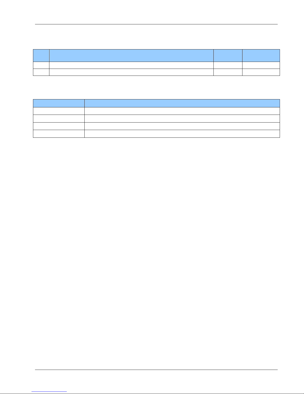
System
Card Rack
Number of Signal Types Supported
Type
End
P/N [Type]
Width
(HP)
Serial Data
Composite
(Analog)
Video
Ethernet
RS-232
(Dedicated)
AIB Plug-In cards*
(Reconfigurable)
10/100M
4VID
Remote
903-0004-03 [CBP-100-XR]
12 4 4
4
1
Console
903-0007-07 [CBP-121-XC]
42 - 8
8VID
Remote
903-0005-12 [CBP-200-XR]
16 8 8
8
1
Console
903-0007-06 [CBP-241-XC]
50 - 16
2.0 System Overview
This document contains information about 903 high density systems based on FMB-X-2.5 boards (fiber
multiplexer boards with optical link running at 2.5 Gbaud).
A high density multiplexer system consists of a Model 903-HD high density remote module (vehicle or ROV
end) and a standard Model 903 console module (surface or shipboard end). The console module is provided
completely packaged in a Eurocard rack integrated with a power supply and all necessary optical
components. (Eurocard PCB dimensions are 100 x 160 mm.) The remote module is provided as a complete
rack, including backplane, fan, and a data I/O box.
The high density remote modules can be provided in 12 HP or 16 HP racks depending on the number of
video and data channels required.
The standard console modules can be provided in 42 HP or 50 HP racks. Note that 4HP corresponds to a slot
width of 0.8 inches or roughly 20 mm.
2.1 Multiplexer Systems
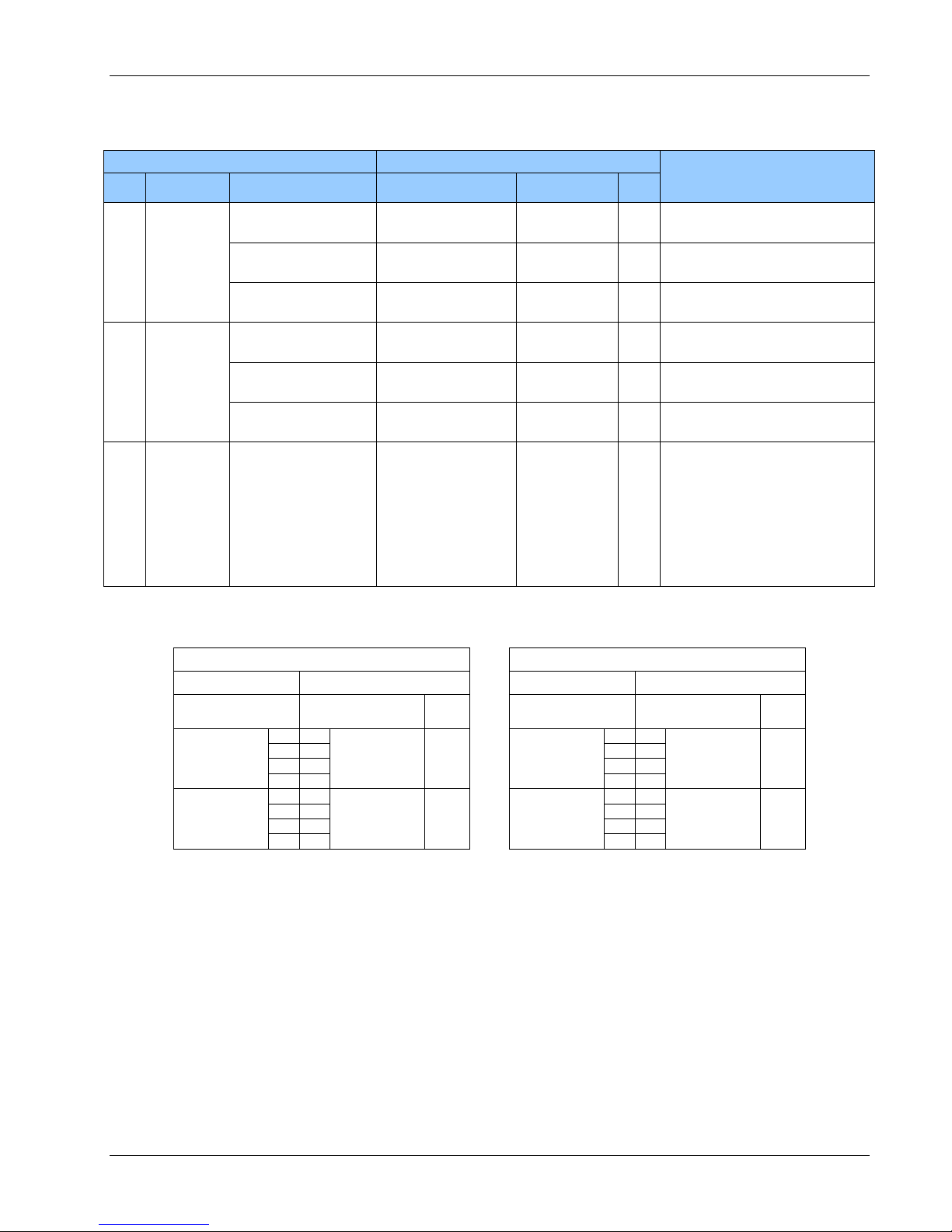
There are two types of 903 high density systems that are covered by this document. One type is the
4VID system which includes 4 composite/analog video channels and the other type is the 8VID system
with 8 composite/analog video channels. The following table provides a summary of the signal types
supported by these systems.
Table 2-1: Model 903-HD Systems – Signal Types Supported
* AIB Plug-In supported signal types include: RS-232, RS-485, RS-422, TTL, Tritech Sonar ARCNET,
Hydrophone/Analog, MS-900 Analog Sonar and CAN Bus (see section 4.3.1 for more details).
Focal Technologies Corp. Page 2-1
Page 11

A B
EXTERNAL
FIBER OPTIC
SYSTEM
REMOTE
MODULE
BOTTOM VIEW
CONSOLE
MODULE
(BACK)
(FRONT)
1 x 10/100 MBPS
ETHERNET/
DIAGNOSTIC
1 x RS-232
DIAGNOSTIC
4 x VIDEO
INPUT (B)
4 x RS-232
(DEDICATED)
4 x SERIAL
(AIB PLUG-IN,
RECONFIGURABLE)
4 x VIDEO
OUTPUT (B)
1 x 10/100 MBPS
ETHERNET/
DIAGNOSTIC
1 x RS-232
DIAGNOSTIC
4 x RS-232*4 x SERIAL*
*AIB PLUG-IN, RECONFIGURABLE
903-0628-00 Rev. 1 Model 903-HD User's Guide – FMB-X-2.5
The figure below shows the I/O ports and optical connections of a 903-HD 4VID system.
Figure 2-1: Model 903-HD Multiplexer – I/O Ports (4VID System)
Focal Technologies Corp. Page 2-2
Page 12
EXTERNAL
FIBER OPTIC
SYSTEM
4 x SERIAL*
(B)
4 x RS-232*
(A)
REMOTE
MODULE
BOTTOM VIEW
CONSOLE
MODULE
(BACK)
(FRONT)
1 x 10/100 MBPS
ETHERNET/
DIAGNOSTIC
1 x RS-232
DIAGNOSTIC
4 x VIDEO
INPUT (A)
4 x VIDEO
OUTPUT (B)
1 x 10/100 MBPS
ETHERNET/
DIAGNOSTIC
1 x RS-232
DIAGNOSTIC
4 x SERIAL*
(A)
4 x RS-232*
(B)
4 x VIDEO
INPUT (B)
4 x VIDEO
OUTPUT (A)
A B
4 x RS-232 (B)
(DEDICATED)
4 x SERIAL (A)
(AIB PLUG-IN,
RECONFIGURABLE)
4 x RS-232 (A)
(DEDICATED)
4 x SERIAL (B)
(AIB PLUG-IN,
RECONFIGURABLE)
*AIB PLUG-IN, RECONFIGURABLE
A B
903-0628-00 Rev. 1 Model 903-HD User's Guide – FMB-X-2.5
The figure below shows the I/O ports and optical connections of a 903-HD 8VID system.
Figure 2-2: Model 903-HD Multiplexer – I/O Ports (8VID System)
Focal Technologies Corp. Page 2-3
Page 13
903-0628-00 Rev. 1 Model 903-HD User's Guide – FMB-X-2.5
SLOT: 0 A B C D E F
Console
SLOT
DESCRIPTION
0
BLANK PANEL,
4HP ASSEMBLY
A
BLANK PANEL,
4HP ASSEMBLY
B
VIB-X-C,
CONSOLE 4x VIDEO
OUTPUT CARD
C
FMB-X-2.5C,
FIBER MULTIPLEXER
BOARD
D
AIB-4 WITH 4x AIB
PLUG-IN MODULES
E
AIB-4 WITH 4x AIB
PLUG-IN MODULES
F
POWER SUPPLY
CAGE
CBP-121-XC, 42 HP
SLOT: B C
Remote
SLOT
DESCRIPTION
B
REMOTE HIGH
DENSITY CARD
C
FMB-X-2.5R,
FIBER MULTIPLEXER
BOARD
CAGE
CBP-100-XR, 12 HP
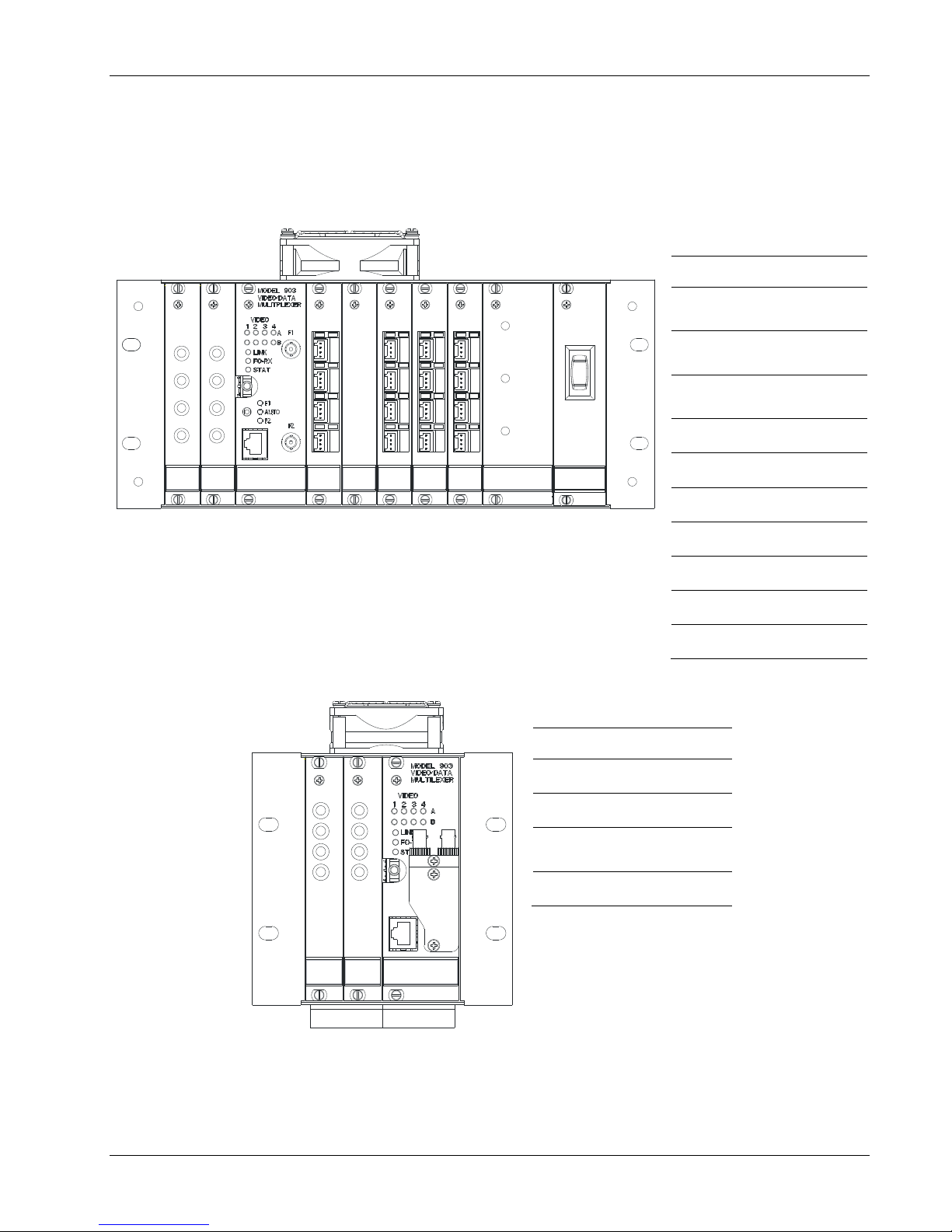
2.2 Rack Configuration
This section provides information about the remote and console module configuration of the 4VID and 8VID
systems covered in this document. Slots in each rack are referenced by letter, per the installation drawings
903-8xxx-xx.
2.2.1 4VID Console and Remote Modules
The 4VID console and remote front panel views are shown in the figure below. This figure also shows a brief
description of each card and the card’s slot position/letter. Note that the as-installed configuration may differ if
cards, such as the AIB-plugins, have been changed to accommodate new interface requirements. More
details can be found in the 903-8xxx-xx installation drawings.
Figure 2-3: Model 903-HD Mux Front Panel View – Card Configuration (4VID)
Focal Technologies Corp. Page 2-4
Page 14
903-0628-00 Rev. 1 Model 903-HD User's Guide – FMB-X-2.5
SLOT: B CA D E F G H I
Console
SLOT
DESCRIPTION
A
VIB-X-C,
CONSOLE 4x VIDEO
OUTPUT CARD
B
VIB-X-C,
CONSOLE 4x VIDEO
OUTPUT CARD
C
FMB-X-2.5C,
FIBER MULTIPLEXER
BOARD
D
AIB-4 WITH 4x AIB
PLUG-IN MODULES
E
BLANK PANEL,
4HP ASSEMBLY
F
AIB-4 WITH 4x AIB
PLUG-IN MODULES
G
AIB-4 WITH 4x AIB
PLUG-IN MODULES
H
AIB-4 WITH 4x AIB
PLUG-IN MODULES
I
POWER SUPPLY
CAGE
CBP-241-XC, 50 HP
SLOT: A B C
Remote
SLOT
DESCRIPTION
A
REMOTE HIGH
DENSITY CARD
B
REMOTE HIGH
DENSITY CARD
C
FMB-X-2.5R,
FIBER MULTIPLEXER
BOARD
CAGE
CBP-200-XR, 16 HP
2.2.2 8VID Console and Remote Modules
The 8VID console and remote front panel views are shown in the figure below. This figure also shows a brief
description of each card and the card’s slot position/letter. Note that the as-installed configuration may differ if
cards, such as the AIB-plugins, have been changed to accommodate new interface requirements. More
details can be found in the 903-8xxx-xx installation drawings.
Figure 2-4: Model 903-HD Mux Front Panel View – Card Configuration (8VID)
Focal Technologies Corp. Page 2-5
Page 15
903-0628-00 Rev. 1 Model 903-HD User's Guide – FMB-X-2.5
REMOTE
MODULE
CONSOLE
MODULE
BOTTOM VIEW
(12 HP I/O BOX)
HDB-TX-B
TR TR
AIB RS-232
FOCAL
1
2
3
4
5
6
7
8
4 x VIDEO
HDB-TX-B
4 x SERIAL (AIB PLUG-IN)
4 x RS-232
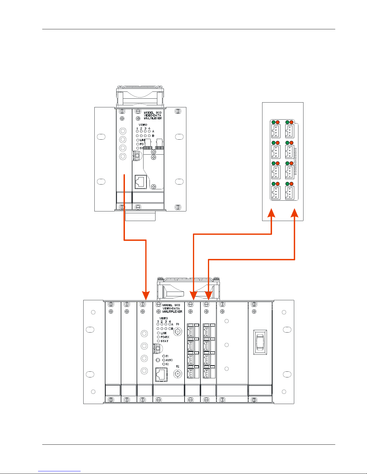
2.2.3 Channel Mapping
2.2.3.1 4VID Remote-to-Console Channel Mapping
The following figure shows the remote-to-console channel mapping of a 903-HD 4VID system.
Figure 2-5: Console and Remote Modules (4VID) Showing Slot Pairings for Video and Data
Focal Technologies Corp. Page 2-6
Page 16
903-0628-00 Rev. 1 Model 903-HD User's Guide – FMB-X-2.5
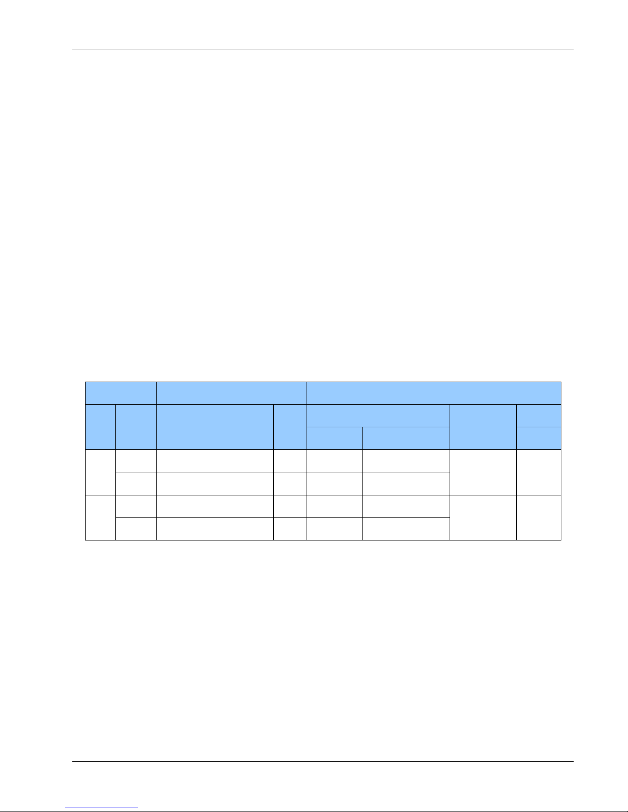
Remote Module
Console Module
Typical Configuration
Slot
Card Type
Signal Type &
Channel @ Remote
Signal Type &
Channel @ Console
Card Type
Slot
B
HDB-TX-B*
Video Input (B)
CH 1-4
Video Output (B)
CH 1-4
VIB-RX
B
All channels NTSC/PAL,
10-bit video.
SERIAL I/O
CH 1-4
SERIAL I/O
CH 1-4
AIB-4 with AIB
Plug-Ins
D
4 x RS-485 @ 115 Kbaud
RS-232 I/O
CH 5-8
RS-232 I/O
CH 1-4
AIB-4 with AIB
Plug-Ins
E
4 x RS-232 @ 115 Kbaud
C
FMB-X-
2.5R-
SMST-DF
Optical Video/Data
Mux with
10/100 Mbps Ethernet
and Diagnostic Data
Slots: B, C
Optical 50/50 Splitter
Ports F1/F2
Optical Video/Data
Mux with
10/100 Mbps Ethernet
and Diagnostic Data
Slots: B, C, D, E
Auto/Manual
Fiber Sw Ports F1/F2
FMB-X-2.5C-
SMST-DF
C
FMB transports all video & data
to/from cards in the specified slots.
2.5 Gbaud (Uplink/Downlink)
F1=F2=Same Optical Data
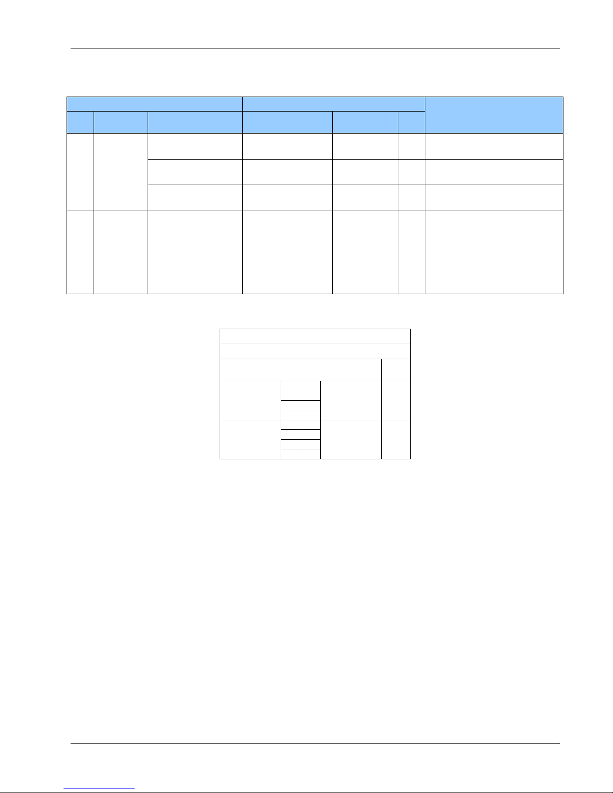
HDB-TX-B Data Channel Mapping
Remote
Console
I/O-Box B
Channels
AIB-4
Channels
Slot
4x SERIAL
(AIB Plug-In)
1
1
4x SERIAL
(AIB Plug-In)
D
2 2 3
3
4
4
4x RS-232
5
1
4x AIB-232
E
6
2
7 3 8
4
A complete mapping of remote to console channels of a 4VID system is given in the following table.
Table 2-2: Typical Remote-to-Console Channel Mapping (4VID System)
*The data channel mapping and AIB plug-in cards used on the HDB-TX-B for a 4VID system is as follows:
Focal Technologies Corp. Page 2-7
Page 17
903-0628-00 Rev. 1 Model 903-HD User's Guide – FMB-X-2.5
HDB-TX-B
TR TR
AIB RS-232
FOCAL
1
2
3
4
5
6
7
8
HDB-TX-A
TR TR
AIB RS-232
FOCAL
1
2
3
4
5
6
7
8
BOTTOM VIEW
16 HP I/O BOX
REMOTE
MODULE
CONSOLE
MODULE
4 x SERIAL (AIB PLUG-IN)
4 x RS-232
4 x SERIAL
(AIB PLUG-IN)
4 x RS-232
4 x VIDEO
HDB-TX-A
4 x VIDEO
HDB-TX-B
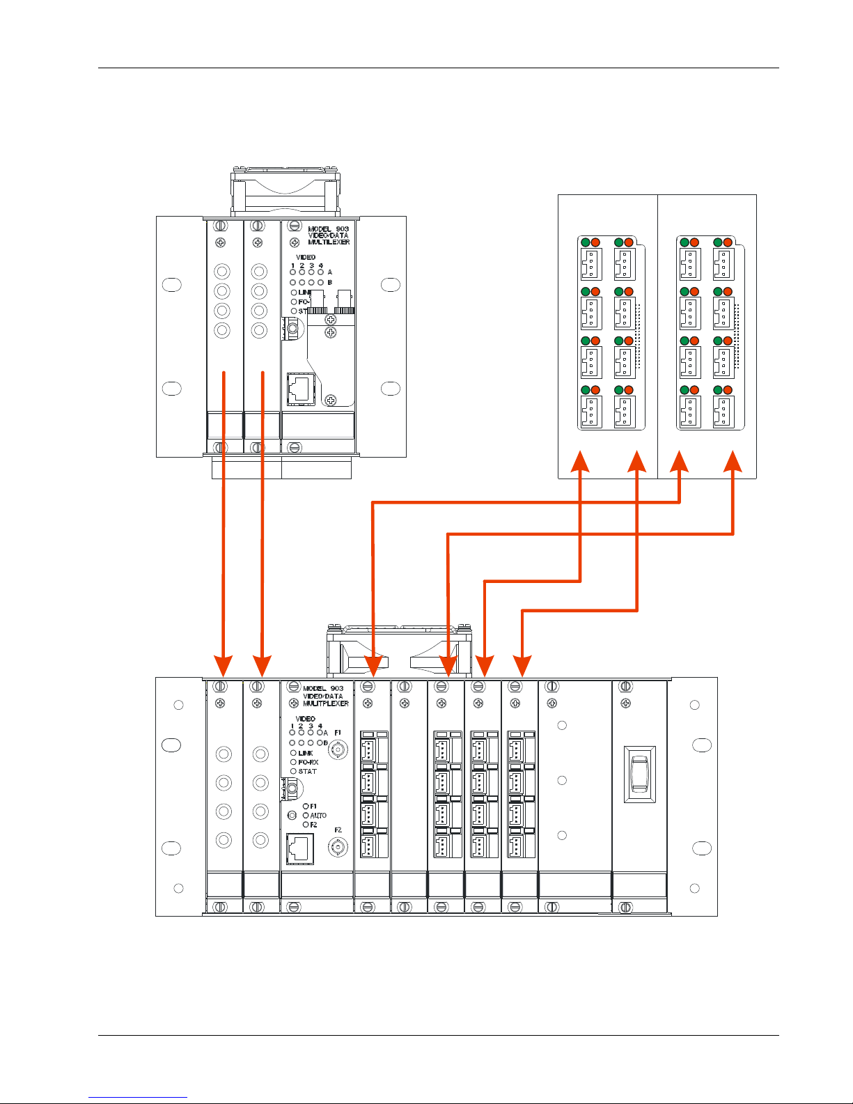
2.2.3.2 8VID Remote-to-Console Channel Mapping
The following figure shows the remote-to-console channel mapping of a 903-HD 8VID system.
Figure 2-6: Console and Remote Modules (8VID) Showing Slot Pairings for Video and Data
Focal Technologies Corp. Page 2-8
Page 18
903-0628-00 Rev. 1 Model 903-HD User's Guide – FMB-X-2.5
Remote Module
Console Module
Typical Configuration
Slot
Card Type
Signal Type &
Channel @ Remote
Signal Type &
Channel @ Console
Card Type
Slot
A
HDB-TX-A*
Video Input (A)
CH 1-4
Video Output (A)
CH 1-4
VIB-RX
A
All channels NTSC/PAL,
10-bit video.
SERIAL I/O
CH 1-4
SERIAL I/O
CH 1-4
AIB-4 with AIB
Plug-Ins
G
4 x RS-232 @ 115 Kbaud
RS-232 (A) I/O
CH 5-8
RS-232 I/O
CH 1-4
AIB-4 with AIB
Plug-Ins
H
4 x RS-232 @ 115 Kbaud
B
HDB-TX-B*
Video Input (B)
CH 1-4
Video Output (B)
CH 1-4
VIB-RX
B
All channels NTSC/PAL,
10-bit video.
SERIAL I/O
CH 1-4
SERIAL I/O
CH 1-4
AIB-4 with AIB
Plug-Ins
D
4 x RS-485 @ 115 Kbaud
RS-232 (B) I/O
CH 5-8
RS-232 I/O
CH 1-4
AIB-4 with AIB
Plug-Ins
F
4 x RS-232 @ 115 Kbaud
C
FMB-X-
2.5R-
SMST-DF
Optical Video/Data
Mux with
10/100 Mbps Ethernet
and Diagnostic Data
Slots: A, B, C
Optical 50/50 Splitter
Ports F1/F2
Optical Video/Data
Mux with
10/100 Mbps Ethernet
and Diagnostic Data
Slots: A, B, C, D, F,
G, H
Auto/Manual
Fiber Sw Ports F1/F2
FMB-X-2.5C-
SMST-DF
C
FMB transports all video & data
to/from cards in the specified slots.
2.5 Gbaud (Uplink/Downlink)
F1=F2=Same Optical Data
HDB-TX-A Data Channel Mapping (Typical)
Remote
Console
I/O-Box A
Channels
AIB-4
Channels
Slot
4x SERIAL
(AIB Plug-In)
1
1
4x SERIAL
(AIB Plug-In)
G
2
2
3
3
4
4
4x RS-232
5
1
4x AIB-232
H
6 2 7
3
8
4
HDB-TX-B Data Channel Mapping (Typical)
Remote
Console
I/O-Box B
Channels
AIB-4
Channels
Slot
4x SERIAL
(AIB Plug-In)
1
1
4x SERIAL
(AIB Plug-In)
D
2
2
3
3
4
4
4x RS-232
5
1
4x AIB-232
F
6 2 7
3
8
4
A complete mapping of remote to console channels of an 8VID system is given in the following table.
Table 2-3: Typical Remote-to-Console Channel Mapping (8VID System)
*The data channel mapping and AIB plug-in cards used on the HDB-TX-A and HDB-TX-B for an 8VID system is as follows:
2.3 System Expansion
The cards in the 4VID and 8VID systems may be changed to provide a different mix of signal types or
increase the number of serial channels.
Please contact the factory prior to any system upgrades or reconfiguration.
Focal Technologies Corp. Page 2-9
Page 19
903-0628-00 Rev. 1 Model 903-HD User's Guide – FMB-X-2.5
WDM
SPLITTER
WDMFIBER
SWITCH
ST (FC OPTIONA L)
LC-LC
LC-LC
SMF-28 FIBER
FIBER SYSTEM (FORJ , FIBER,
CONNECTORS, J UNCTION BO XES)
SMF-28 FIBER
REMOTE MODULE FMB-X-2.5-R
CONSOLE MODULE FMB-X-2.5-C
ST
(FC OPTIONA L)
SFP
TXVR
LC
LC
SFP
TXVR
LC
LC
TX 1310 nm
RX 1550 nm
TX 1550 nm
RX 1310 nm
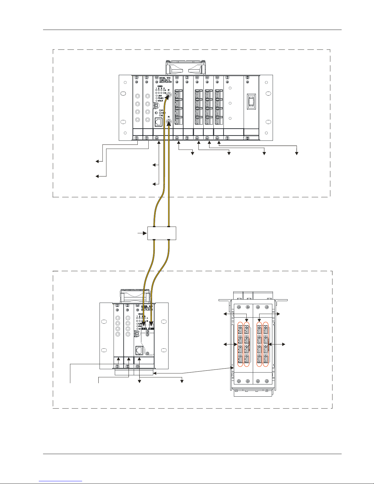
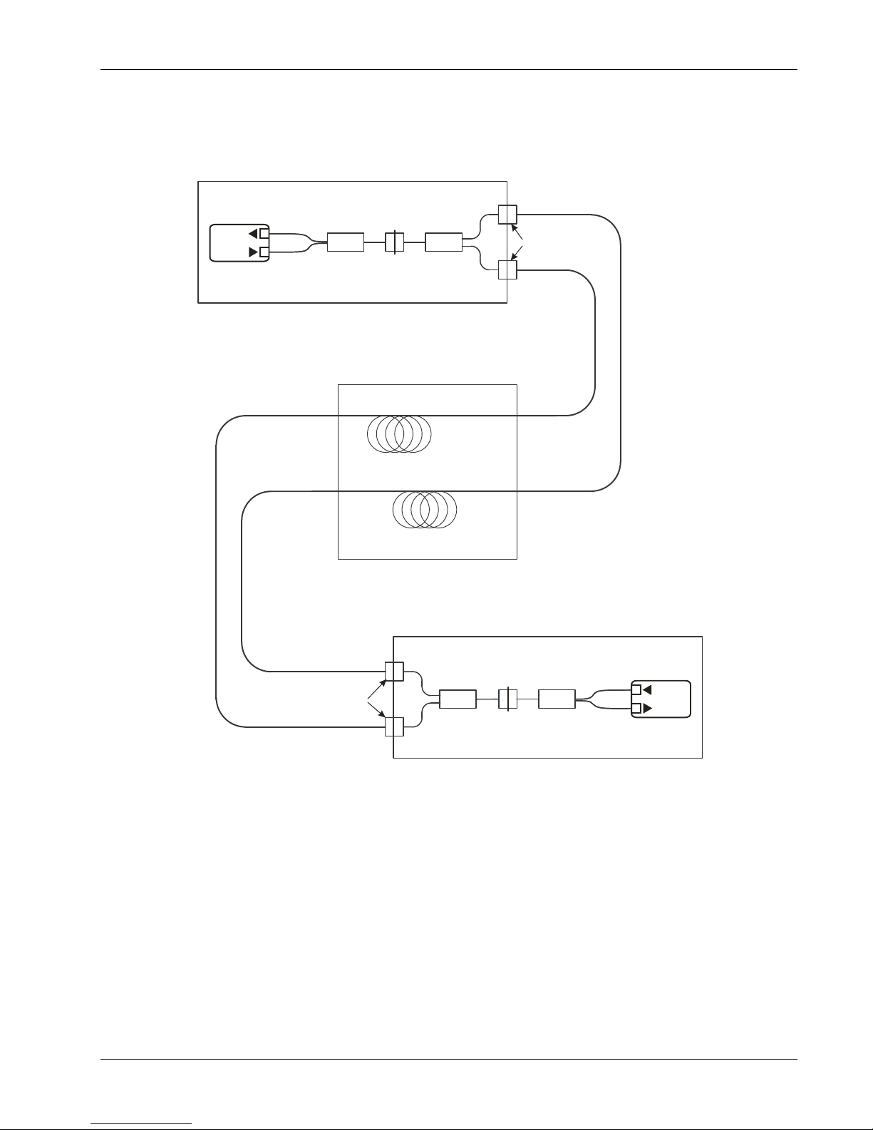
2.4 Optical Configuration
The optical configuration of a 4VID and 8VID dual fiber systems is shown in the figure below.
Figure 2-7: Model 903 Dual Fiber Optic Transmission System (4VID, 8VID)
The FMB-X-2.5R card in the remote subrack optically multiplexes the 1310 nm uplink and 1550 nm downlink
on the same fiber with a standard 1310/1550 nm WDM. A second 1310/1550 nm WDM at the FMB-X-2.5C
card multiplexes the uplink and downlink to the receiver and transmitter respectively.
The remote FMB-X-2.5R includes an optical splitter to provide redundant signals over two separate
singlemode fibers. At the console module, one of the two fibers for each link is selected by the fiber switch
integrated with the FMB-X-2.5-C located in slot C. Hence the downlink is only present on one fiber at a time.
The fiber switching can be performed automatically or manually, depending on the position of the toggle
switch on the front panel of the FMB-X-2.5C card. Refer to section 3.1.2 for more information about the
FMB-X-2.5C.
Focal Technologies Corp. Page 2-10
Page 20

903-0628-00 Rev. 1 Model 903-HD User's Guide – FMB-X-2.5
2.5 Backwards Compatibility
The FMB-X-2.5 is not backwards compatible with the FMB-VTX, FMB-VRX or GLINK FMB-X cards.
Both remote and console FMBs must be replaced with the FMB-X-2.5 when upgrading. All FMB-X-2.5 cards
operate at 2.5 Gbaud on uplink (1310 nm) and downlink (1550 nm) and are compatible with existing video
cards, data cards, and high speed racks. In the case of medium speed racks, the FMBs and backplanes must
be changed out.
Contact factory for more information.
Focal Technologies Corp. Page 2-11
Page 21
903-0628-00 Rev. 1 Model 903-HD User's Guide – FMB-X-2.5
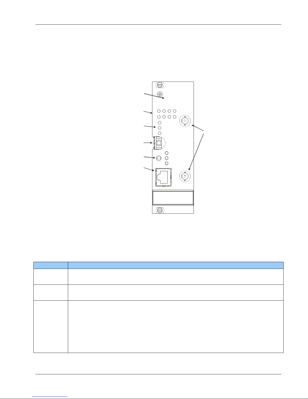
STAT
FO-RX
LINK
VIDEO SYNC
LEDS (SLOT A/B)
STATUS LEDS
(LINK, FO-RX, STAT)
DIAGNOSTICS SERIAL
PORT (RS-232)
ETHERNET PORT
OPTICAL LINK RATE
GLINK FMB-X = 10M
FMB-X-2.5 = 100M
REDUNDANT
FIBER PORTS
(SPLITTER)
DUAL ST/PC
A B 1 2 3
4
VIDEO
MODEL 903
VIDEO/DATA
MULTIPLEXER
100M
ETHERNET RATE TEXT
BLANK OR 10M = GLINK FMB-X
100M = FMB-X-2.5
3.0 Fiber Multiplexers and Backplanes
Fiber Multiplexer Boards (FMBs) are used to combine all of the video, Ethernet, and data signals into a single
optical link and then regenerate the original copper signals at the other end of the system. Backplane cards
are used to connect all of the Model 903 cards together within remote or console modules. A complete Model
903 system includes at least one remote and one console module.
3.1 FMB-X-2.5 Fiber Multiplexer Board
The FMB-X-2.5 cards use FPGA SERDES (Serializer/Deserializer) modules that run at an optical data rate of
2.5 Gbaud on both uplink and downlink. This high optical data rate allows more capacity for video, data and
Ethernet traffic than older FMBs. FMB-X-2.5 cards are designed to work only with singlemode fibers to
support the high data rates. System diagnostics can be accessed via the RS-232 port or RJ-45 Ethernet port
of both remote and console FMB-X-2.5 cards. More information about diagnostics is provided in the
diagnostics manual (P/N 903-0622-00).
Note: The FMB-X-2.5 FPGA-based SERDES optical link is not optically compatible with GLINK-based FMB
cards such as FMB-VTX, FMB-VRX or GLINK FMB-X cards. These older cards must be updated in pairs
(remote and console). More details about upgrading to FMB-X-2.5 are found in the Model 903 User’s Guide
903-0623-00.
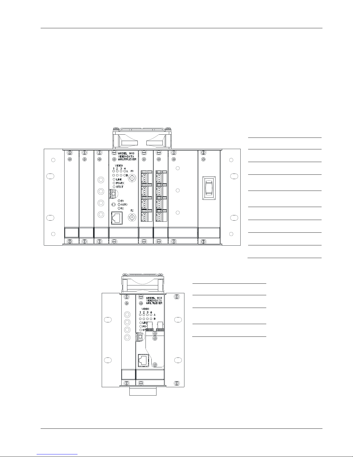
3.1.1 Remote FMB-X-2.5
Card P/N 903-5082-00
The front panel view of the remote FMB-X-2.5 is shown in the figure below. Redundant ST fiber connectors
are accessible on the right angled turret. An internal splitter provides roughly equal power output levels on
both ST connectors. Typically the output power should be greater than -6 dBm at 1310 nm (uplink) and the
receive sensitivity at the turret should be better than -24 dBm at 1550 nm (downlink).
Focal Technologies Corp. Page 3-1
Figure 3-1: Remote FMB-X-2.5 Front Panel View
Page 22
903-0628-00 Rev. 1 Model 903-HD User's Guide – FMB-X-2.5
RX 1550 nm
TX 1310 nm
SFP
TRANSCEIVER
DUAL ST
BUSHING
TURRET
OPTICAL
DAUGHTERCARD
SFP CAGE
DIN 41612
96-PIN
BACKPLANE
CONNECTOR
LEDs on the front panel match those described in the console FMB-X-2.5 section and allow direct monitoring
of the optical link status (LINK), optical receive power (FO-RX), and the status (STAT) of the on-board
diagnostics. See the console FMB-X-2.5 section for more details on LEDs.
The Ethernet port supports both 10 Mbps and 100 Mbps devices on the copper link. The optical Ethernet link
through the multiplexer is 100 Mbps. The older GLINK FMB-X supports only 10 Mbps through the multiplexer.
The maximum data rate supported by the Ethernet link is indicated on the panel silk screen and is an easy
way to differentiate the FMB-X-2.5 (100M) and older FMB-X (10M) cards.
Diagnostics for the FMB-X-2.5 can be accessed at the RS-232 port on both remote and console cards, and
also via the RJ-45 Ethernet port at both remote and console ends. See console FMB-X-2.5 for more
information about diagnostics and also refer to diagnostics manual 903-0622-00.
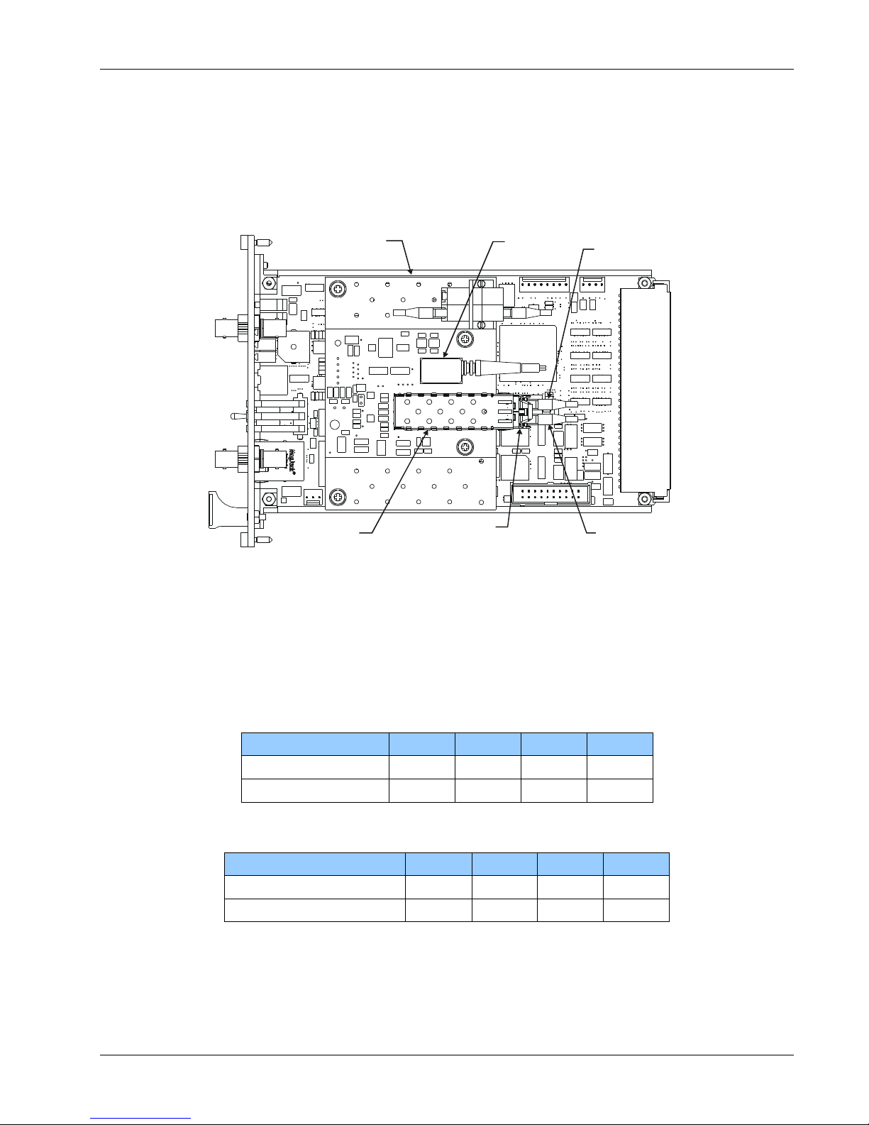
A plan view of the remote FMB-X-2.5 is shown in the figure below. The 1310/1550 nm singlemode WDM
coupler and 1 x 2 splitter are not visible: both are mounted on the underside of the optical daughtercard below
the two dual LC bushings shown.
Figure 3-2: Remote FMB-X-2.5 Plan View
No customer switch settings are required for configuration of the FMB-X-2.5 remote card. All video channels
are handled at 10-bit digitization and all data slots are sampled as “high speed” slots, similar to slot “D” on
older 903 systems.
Focal Technologies Corp. Page 3-2
Page 23
903-0628-00 Rev. 1 Model 903-HD User's Guide – FMB-X-2.5
VIDEO SYNC
LEDS (SLOT A/B)
STATUS LEDS
(LINK, FO-RX, STAT)
DIAGNOSTICS SERIAL
PORT (RS-232)
REDUNDANT
FIBER PORTS
(SWITCH)
DUAL ST/PC
FIBER SWITCH
CONTROL/STATUS
ETHERNET PORT
OPTICAL LINK RATE
GLINK FMB-X = 10M
FMB-X-2.5 = 10 0M
ETHERNET RATE TEXT
BLANK OR 10M = GLINK FMB -X
10 0M = FMB-X-2.5
MODEL 903
VIDEO/DATA
MULTIPLEXER
100M
VIDEO
1 2 3 4
LINK
FO-RX
STAT
F1
F1
AUTO
F2
F2
A
B
LED
Description
VIDEO
VIDEO LEDs are green when video sync is detected on each video channel from slot A and
slot B in the rack.
LINK
LINK LED is green when a valid optical link is being received and red if no link is present. A
valid optical link means that the local FMB is receiving valid data frames from the far end card.
FO-RX
FO-RX LED is green when the received optical power is within specified operating range, i.e.
above the minimum sensitivity and below the saturation level. This LED will change to orange
(warning) when the receive power is within roughly 2-3 dB of the receiver failing at low power
or within roughly 1-2 dB of saturating and failing at high power. The LED will change to red
(alarm) when the power level is either too low or too high to provide a reliable optical link,
although in some cases the link will still be functional with a higher than normal bit error rate.
Warning and alarm thresholds are stored in registers in the SFP transceivers. Problems with
optical power should be investigated using the diagnostic software and/or fiber optic power
meters.
3.1.2 Console FMB-X-2.5
Card P/N 903-5083-00
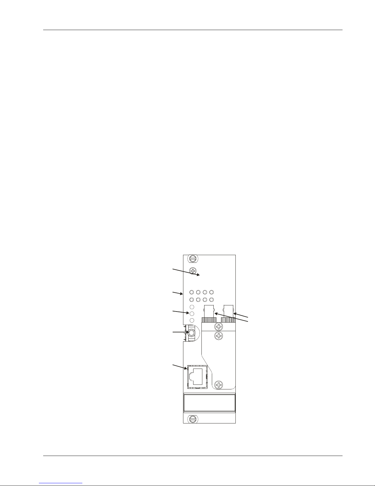
The front panel view of the console FMB-X-2.5 is shown in the figure below. Redundant ST fiber connectors
are accessible as straight bushings on the front panel marked "F1" and "F2". An internal fiber switch chooses
one of the fibers for the optical link, either automatically or manually via the front panel toggle switch. Typically
the output power should be greater than -2 dBm at 1550 nm (downlink) and the receive sensitivity at the front
panel should be better than -28 dBm at 1310 nm (uplink).
Figure 3-3: Console FMB-X-2.5 Front Panel
LEDs on the front panel of the remote or console FMB-X-2.5 provide status of video channels, optical link,
and card health per table below.
Table 3-1: FMB-X-2.5 Front Panel LEDs
Focal Technologies Corp. Page 3-3
Page 24
903-0628-00 Rev. 1 Model 903-HD User's Guide – FMB-X-2.5
LED
Description
STAT
STAT (Status) LED is green when on-board diagnostic readings are within expected values.
The STAT LED is orange (warning) if any of the on-board diagnostic readings are close to an
alarm state. The STAT LED is red (alarm) if any of the on-board diagnostic readings are
outside of the specified range, in which case the diagnostic software should be used to
troubleshoot the problem. Monitored signals included temperature and all major voltage rails
(+12V, -12V, +5V, and +3.3V). An alarm state exists if any voltage is worse than ±20% of
nominal value or temperature is > +80C. A warning state exists if any voltage is worse than
±10% of nominal value or temperature is > +75C, but the reading is not in an alarm state.
F1/F2
F1/F2 LEDs indicate which fiber is active, per the marked ST bushings. The active fiber is
shown by the green LED. The LED(s) will turn red if no link is present.
AUTO
AUTO LED is green when the fiber switch is in automatic mode, as determined by the toggle
switch position. When in automatic mode and there is no link, this LED will be red.
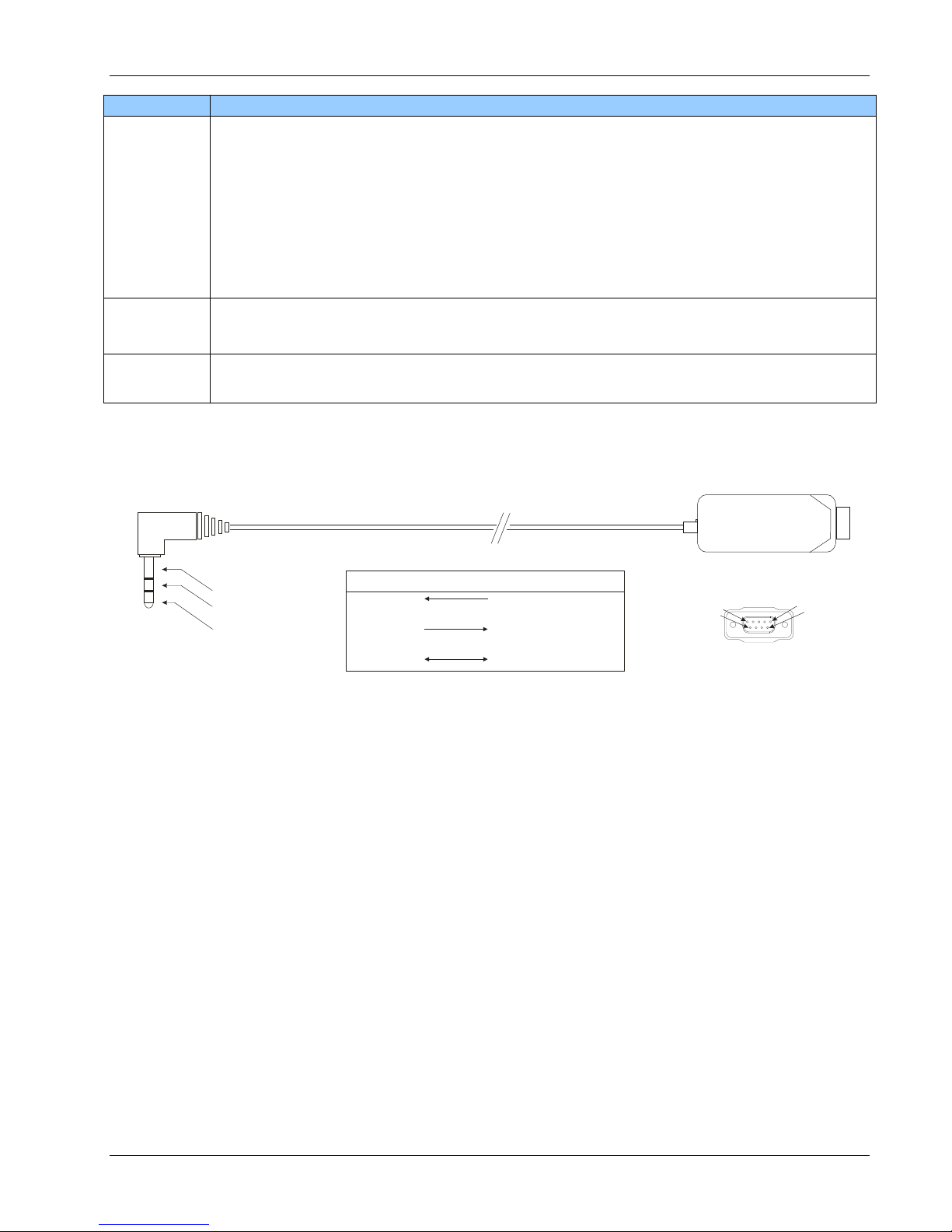
1/8” (3.5 mm) STEREO PLUG, RT ANGLE
DB9 FEMALE
3 - GROUND
2
1
P1
P2
STEREO PLUG : P1 DB9F : P2
P1:1
P1:2
P1:3
P2:3 TX
(DATA FROM PC TO FMB)
P2:2 RX
P2:5 GND
(DATA INTO PC FROM FMB)
DB9F FRONT VIEW
5
9
1
6
TO FMB
TO PC
Diagnostics are available at the 1/8" (3.5 mm) stereo jack in RS-232 format compatible with the standard
Model 903 Diagnostics GUI software, e.g. 903-0406-00. Wiring for the RS-232 connections is shown in the
figure below.
Figure 3-4: FMB-X-2.5 RS-232 Diagnostic Cable: 1/8” (3.5 mm) Stereo to DB9F
The functions described in the figure above are relative to the PC (DB9 side), i.e. TX is data transmitted from
the PC to the FMB-X-2.5 and RX is data received into the PC from the FMB-X-2.5. This RS-232 interface also
has command based diagnostics, which provides advanced diagnostics information. See 903-0622-00
diagnostic manual for more information.
Diagnostics are also available via the RJ-45 port as Modbus TCP/IP or through an embedded web server.
Since this port is also used for general Ethernet traffic between remote and console, diagnostics packets are
handled as low priority and must be polled by the external computer. When accessed, diagnostic data
packets typically use up less than 0.1% of the Ethernet channel capacity.
The fiber switch may be placed in automatic mode or forced to fiber F1 or F2 using the front panel toggle
switch (toggle up forces the fiber switch to F1 and toggle down forces it to F2). In automatic mode, with the
toggle switch in the center position, the FMB-X-2.5 tests both fibers on initial power up and chooses the one
with the highest optical power. This will stay locked until the switch is forced to the other fiber, via the toggle
switch, or link is lost on the active fiber. The active fiber is indicated by a green LED next to either F1 or F2.
The LED marked "AUTO" is green when in automatic switching mode and off when in manual mode.
When the optical link is lost in auto mode, the switch toggles automatically roughly once per second between
F1 and F2 for up to 10 times. If no link is found, the switch returns to the original fiber it was on before the link
failure and waits for a link to be re-established. In this fault state, the “AUTO”, “F1” and “F2” LEDs are red and
a continuous audible alarm is produced until a fiber link is restored. Power cycling or manually forcing the
toggle switch to a fiber (F1 or F2 position) and then back to AUTO will reset the automatic fiber switch.
Focal Technologies Corp. Page 3-4
Page 25
903-0628-00 Rev. 1 Model 903-HD User's Guide – FMB-X-2.5
RX 1310 nm
TX 1550 nm
FIBER
SWITCH
SFP
TRANSCEIVER
FIBER F1
ST BUSHING
FIBER F2
ST BUSHING
OPTICAL
DAUGHTERCARD
SFP CAGE
DIN 41612
96-PIN
BACKPLANE
CONNECTOR
Description
SW1:1
SW1:2
SW1:3
SW1:4
Remote FMB-X-2.5
ON
ON
ON
ON
Console FMB-X-2.5
OFF
ON
ON
ON
Description
SW2:1
SW2:2
SW2:3
SW2:4
High Density Backplanes
OFF
ON
OFF
OFF
Standard Backplanes
OFF
OFF
OFF
OFF
The FMB-X-2.5 also sounds a continuous audible alarm when an optical link fails in AUTO mode, even if the
other fiber has a valid link. This informs the operator of a fiber fault that otherwise might not be noticed, as the
switchover from one fiber to the other is often seamless. The alarm can be turned off by briefly forcing the
toggle switch to the active fiber in manual mode and then back to the automatic setting. The FMB-X-2.5 alarm
can also be disabled via software commands.
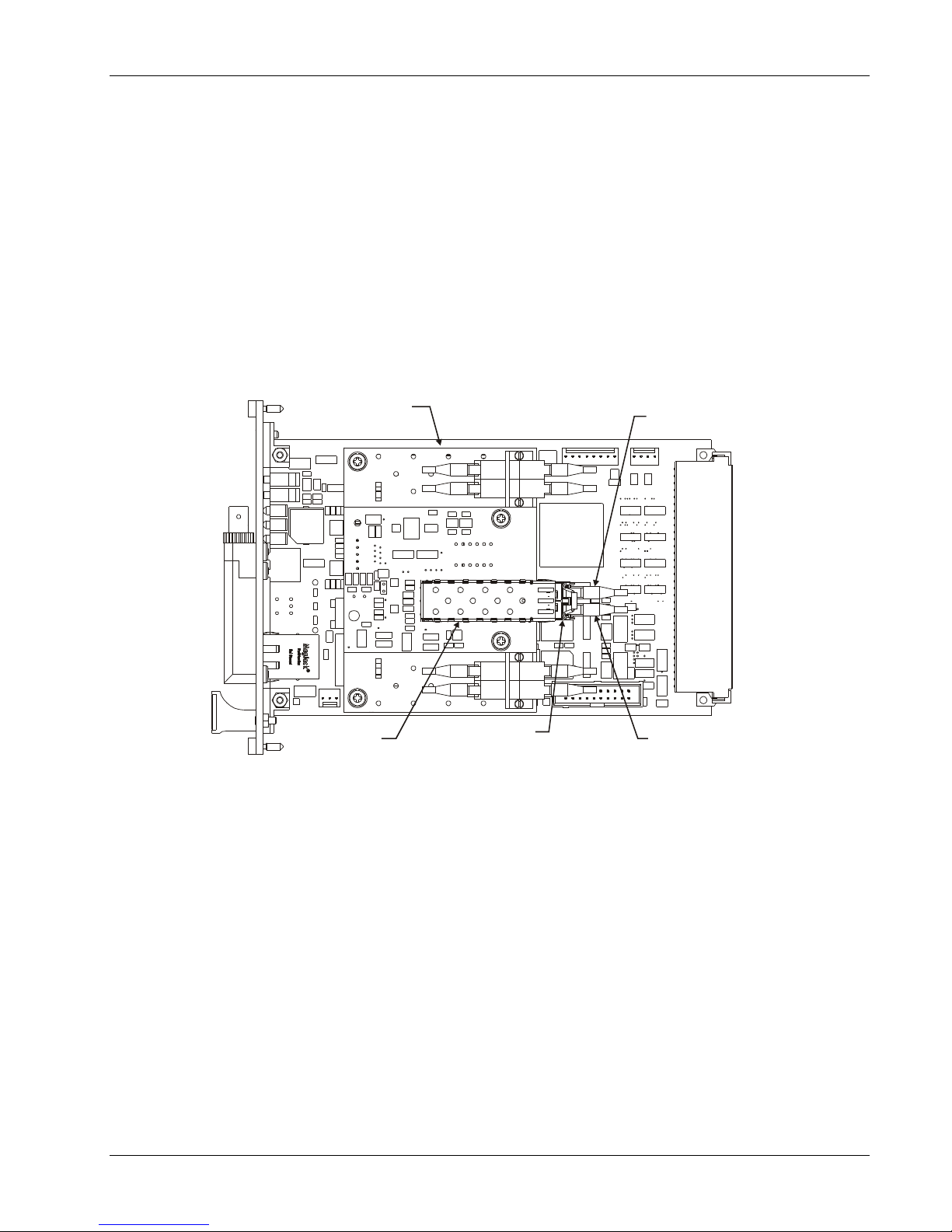
A plan view of the console FMB-X-2.5 is shown below. The 1310/1550 nm singlemode WDM coupler is not
visible and is mounted on the underside of the optical daughtercard below the dual LC bushings shown.
Figure 3-5: Console FMB-X-2.5 Plan View
3.1.3 Configuration Settings
Switch configuration settings for the remote and console FMB-X-2.5 cards are given in the tables below. Note
that both DIP switches (SW1 and SW2) are typically configured at the factory and therefore the
settings should never be changed from their original positions.
Table 3-2: SW1 Configuration Settings
Table 3-3: SW2 Configuration Settings
Focal Technologies Corp. Page 3-5
Page 26
903-0628-00 Rev. 1 Model 903-HD User's Guide – FMB-X-2.5
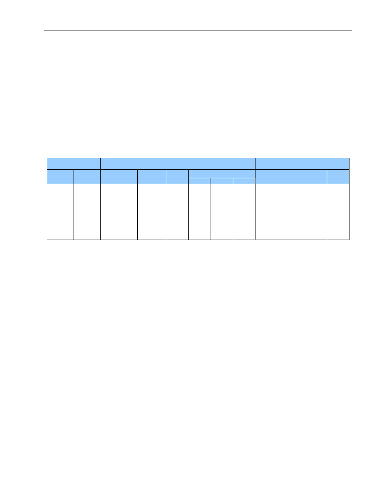
System
-X Backplane
Card Rack
Name
End
P/N
Type
Width
(HP)
Number of Slots
P/N [Type]
Width
(HP)
Video
Data
PSU
4VID
Remote
903-7212-00
High
Density
12 1 0 0 903-0004-03 [CBP-100-XR]
12
Console
903-7213-00
Standard
28 1 2 1 903-0007-07 [CBP-121-XC]
42
8VID
Remote
903-7207-00
High
Density
16 2 0 0 903-0005-12 [CBP-200-XR]
16
Console
903-7210-00
Standard
44 2 4 1 903-0007-06 [CBP-241-XC]
50
3.2 Backplanes (-X Type) and Racks
BP P/N 903-7212-00 for 4VID 903-HD Remote system
BP P/N 903-7213-00 for 4VID 903 Std. Console system
BP P/N 903-7207-00 for 8VID 903-HD Remote system
BP P/N 903-7210-00 for 8VID 903 Std. Console system
The backplane cards are used to connect all the Model 903 cards and PSU modules together to make up a
Model 903 system. There are two main types of backplanes for 903 systems based on FMB-X-2.5 cards. One
is the standard -X backplane and the other is the high density -X backplane. Both types of backplanes provide
diagnostic capabilities that are used to monitor the overall status of the system.
The following table provides a list of the different backplanes used in the 4VID and 8VID systems. This table
also shows a cross reference between the backplane P/Ns and rack P/Ns.
Table 3-4: -X Backplanes Used in 4VID and 8VID Systems
For the 4VID and 8VID systems, each video and data slot occupies a standard 0.8” (4HP=0.8”) width in the
card rack. The FMB-X-2.5 and power supply slots are 1.6” (8HP) wide and the front panel power switch on
the console modules is 1.2” (6HP) wide. Boards are referenced by location within the rack in relation to the
FMB-X-2.5 slot C.
As shown in the table above, the three digits following the CBP- designator (under the “Card Rack” column)
represent the number of video, data, and power supply unit (PSU) slots respectively. An “R” in the suffix
indicates the remote rack and a “C” in the suffix indicates the console rack.
As shown in the table above, the high density -X backplane uses a proprietary 12HP/16HP design including
guided card slots for one or two high density boards (HDB-TX) and one fiber optic multiplexer board
(FMB-X-2.5). Each HDB slot takes a 4HP wide card; each FMB-X-2.5 slot takes an 8HP wide card. Note that
the high density remote racks do not have a PSU slot and instead they have DC-DC converters mounted on
the backplane. These backplanes are single voltage input (+24 VDC).
Focal Technologies Corp. Page 3-6
Page 27
903-0628-00 Rev. 1 Model 903-HD User's Guide – FMB-X-2.5
As a default configuration, AGND and DGND are connected on the backplane through a
ferrite bead. Insulating covers are used over the primary terminals as a safety precaution
and must not be removed while the rack is connected to mains power.
For 230 VAC inputs, typically there are two line connections rather than line and neutral.
The neutral wires and terminals should always be assumed to be at high voltage.
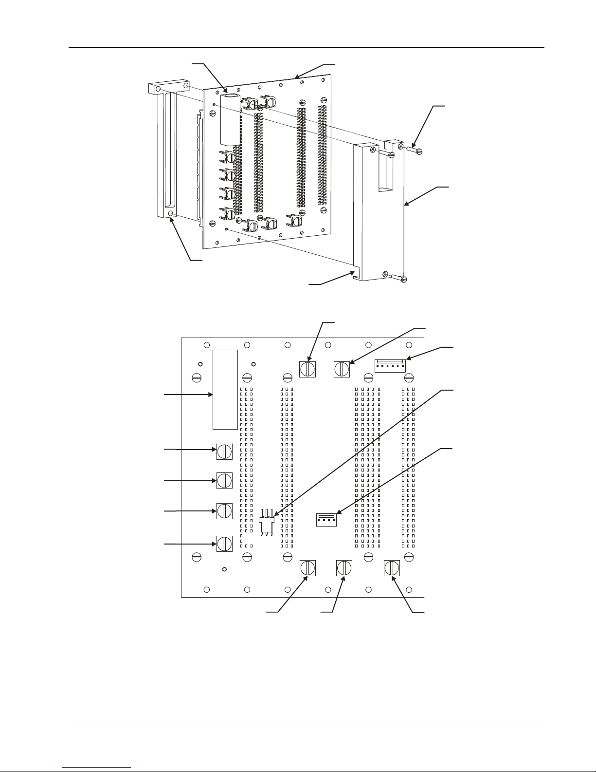
3.2.1 Standard -X Backplanes
Card P/N: 903-7213-00; 903-7210-00
The standard -X backplanes described in this section are used on the 4VID (BP P/N: 903-7213-00,
28 HP) and 8VID (BP P/N: 903-7210-00, 44 HP) console modules.
Assembly views of a 28 HP -X backplane PCB (CBP-121-XR/XC) and a 44 HP -X backplane PCB
(CBP-241-XR/XC) are given in Figure 3-6 and Figure 3-7 respectively. The bottom side of the backplane
faces outwards from the assembly and is accessible by removing the back cover plate. Fuse F1 is a standard
replaceable glass cartridge type for the primary power input (fuse value depends on type of power supply).
Header J15 is a serial number programming port; J13 is a connector to the chassis fan. Rail voltages and
grounds are directly accessible via screw terminals J18, J19, J9, J17, and J10 for +12 V, -12 V, +5 V, AGND
(analog ground), and DGND (digital ground) respectively.
Primary power inputs are wired into screw terminals:
J16 is not connected for AC sources and acts as the 0V reference for DC sources
J12 is neutral for AC sources and is not connected for DC sources
J11 is line for AC sources and +V input for DC sources
J14 is an earth connection that is made through the power supply module to the mechanical rack, but
is otherwise isolated from all other grounds unless external connections are made
Focal Technologies Corp. Page 3-7
Page 28
903-0628-00 Rev. 1 Model 903-HD User's Guide – FMB-X-2.5
J10
DIGITAL GROUND
(DGND)
J9
+5 VDC
Pin 1Pin 6
Pin 1Pin 4
Pin 3 2 1
J1
VIDEO SWITCHING
PORT HEADER
J13
FAN HEADER
PIN 1 = +12 VDC
PIN 2 = TACH
PIN 3 = +12 VDC RETURN
J15
SERIAL NO.
PROGRAMMING
PORT HEADER
J19
-12 VDC
J17
ANALOG GROUND
(AGND)
J18
+12 VDC
J16
AC: N/C
DC: -VIN (GND)
J14
AC: EARTH + CHASSIS
DC: CHASSIS
J12
AC: NEUTRAL
DC: N/C
J11
AC: LINE
DC: +VIN
PRIMARY FUSE (F1)
1 A TIME DELAY
903-7213-00
28 HP “-X” BACKPLANE ASSEMBLY
SLOTS: 1 x VIDEO, 1 x FMB, 2 x DATA, 1 x PSU
3 x M2.5X16mm
CHEESE HD
SS SLOTTED SCREWS
903-0122-01
POWER COVER
ACCESS CUTOUT
FOR POWER WIRING
PRIMARY FUSE (F1)
903-0123-00
INSIDE POWER COVER
Figure 3-6: 28 HP -X Console Backplane (CBP-121-XC)
Focal Technologies Corp. Page 3-8
Page 29
903-0628-00 Rev. 1 Model 903-HD User's Guide – FMB-X-2.5
903-0123-00
INSIDE POWER COVE R
PRIMA RY FUSE (F1)
903-7210-00
44 HP B ACKPLANE -X AS SEMBLY
SLOTS: 2 X VIDEO, 1 X FMB, 4 X DATA,
1 X P SU
3 x M2.5X16mm CHEE SE HD
SS SLOTTED SCREWS
903-0122-00
POWER COVER
J10
DIGITAL GROUND
(DGND)
J9
+5 VDC
Pin32 1
J13
FAN HEADER
PIN 1 = +12 VDC
PIN 2 = TACH
PIN 3 = +12 VDC RETURN
J15
SERIAL NO.
PROGRAMMING
PORT HEADER
J19
-12 VDC
J17
ANALOG GROUND
(AGND)
J18
+12 VDC
J16
AC: N/C
DC: -VIN (GND)
J14
AC: EARTH + CHASS IS
DC: CHASSIS
J12
AC: NEUTRAL
DC: N/C
J11
AC: LINE
DC: +VIN
PRIMA RY FUSE (F1)
1 A TIME DE LAY
Pin 4 Pin 1
Figure 3-7: 44 HP -X Console Backplane (CBP-241-XC)
Focal Technologies Corp. Page 3-9
Page 30

903-0628-00 Rev. 1 Model 903-HD User's Guide – FMB-X-2.5
PROGRAMMING HEADER
(FACTORY USE)
12
1 2
J6
F2
F3
J5
U10
SPARE PRIMARY FUSE
0454005, 5 A SM T,
TIME DELAY
PRIMARY FUSE
0454005, 5 A SM T,
TIME DELAY
PRIMARY INPUT
PIN 1 = DGND
PIN 2 = +24 VDC
DC-DC CONVERTER
+24 VDC INPUT
+12/-12 VDC OUTPUT
FAN HEADER
PIN 1 = + 24 VDC OUT
PIN 2 = DGND
J4
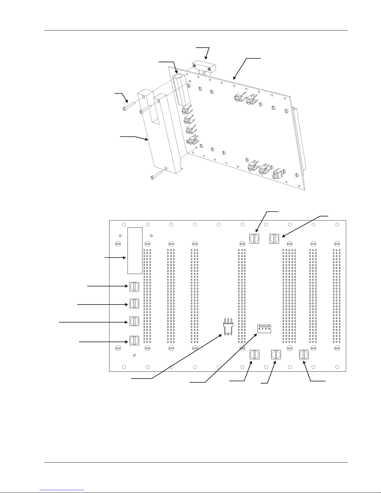
3.2.2 High Density -X Backplanes
Card P/N: 903-7212-00 (12 HP BP); 903-7207-00 (16 HP BP)
The high density -X backplanes described in this section are used on the 4VID (12 HP BP P/N:
903-7212-00) and 8VID (16 HP BP P/N: 903-7207-00) remote modules. These backplanes are +24 VDC
input.
PCBA views of the 12 HP -X backplane PCB (CBP-100-XR) and the 16 HP -X backplane PCB (CBP-200-XR)
are given in Figure 3-8 and Figure 3-9 respectively. These figures show the side that faces outwards from the
back of the remote chassis with the plastic cover removed. The J5 header is connected to a 24 VDC fan on
the remote rack. Only a single +24 VDC input power is required at J6.
The remote module does not have a power switch. Connection of the remote module power supply to primary
supply rails immediately turns the module on. Status of the three internal rail voltages (+5, +12, -12 VDC) is
indicated by the diagnostics software.
The primary input to the remote module is protected with a 5 A time delay fuse, F3, located just below the
power input J6 connector. This fuse may be replaced, if necessary, with the spare fuse F2 located nearby.
Figure 3-8: 12 HP High Density Remote Backplane PCBA (+24 VDC Input)
Focal Technologies Corp. Page 3-10
Page 31

903-0628-00 Rev. 1 Model 903-HD User's Guide – FMB-X-2.5
PROGRAMMING HEADER
(FACTORY USE)
1
2
1 2
J6
F2
F3
J5
U10
SPARE PRIMARY FUSE
0454005, 5 A SM T,
TIME DELAY
PRIMARY FUSE
0454005, 5 A SM T,
TIME DELAY
PRIMARY INPUT
PIN 1 = DGND
PIN 2 = +24 VDC
DC-DC CONVERTER
+24 VDC INPUT
+12/-12 VDC OUTPUT
FAN HEADER
PIN 1 = + 24 VDC OUT
PIN 2 = DGND
J4
Figure 3-9: 16 HP High Density Remote Backplane PCBA (+24 VDC Input)
Focal Technologies Corp. Page 3-11
Page 32

903-0628-00 Rev. 1 Model 903-HD User's Guide – FMB-X-2.5
Power Supply
Description
System End
AC Module (PSU)
115/230 VAC, 60W, 47-63 Hz Auto-ranging
Console
24 VDC
DC-DC Converter, +24 VDC Input, Range 18-36 VDC.
Remote
WARNING: RISK OF ELECTRIC SHOCK
To avoid risk of injury from electric shock, do not
open the enclosure of the power supply module.
Refer servicing to qualified personnel.
3.3 Power Supply
The 4VID and 8VID systems use the power supplies described in the table below.
Table 3-5: Typical Power Supplies for 903 Console and Remote Systems
Console
The 4VID and 8VID console modules use a standard power supply unit (PSU). This PSU is a 3U x 8HP
Eurocassette with a 100 mm guiding height.
Current draw from the primary 115 VAC for a typical console module is approximately 0.3 A.
As shown in Figure 3-10, the console modules have a power switch on the far right panel and a detachable
(IEC-320) power cord on the back cover plate. Status of the three internal rail voltages — +5 VDC, +12 VDC
and -12 VDC — is represented by green LEDs located on the front panel of the power supply module. A
flickering or dim LED indicates a problem with the corresponding rail voltage, possibly caused by an
excessive load.
All standard Eurocassette power supplies provide full transformer isolation between the primary input and the
backplane rail outputs. The 4VID and 8VID console modules use AC input power and therefore the protective
earth lead on the power cable is connected through the Eurocassette frame to the rack of the multiplexer,
which is normally isolated from internal digital and analog ground.
Remote
Each 4VID and 8VID remote module uses two DC-DC converters that are part of the high density -X
backplane. One DC-DC converter (75W) outputs +5 VDC and the other DC-DC converter (10W) outputs
±12 VDC. Each remote module requires +24 VDC input power from a power supply capable of providing 2A.
See Figure 3-10 for DC power connector location.
Focal Technologies Corp. Page 3-12
Page 33

903-0628-00 Rev. 1 Model 903-HD User's Guide – FMB-X-2.5
Console (4VID)
Console (8VID)
POWER
SWITCH
AC POWER
ENTRY
Remote (4VID)
Remote (8VID)
DC POWER IN
DGND +24 VDC
Figure 3-10: Power Connectors Location (4VID and 8VID Systems)
Focal Technologies Corp. Page 3-13
Page 34

903-0628-00 Rev. 1 Model 903-HD User's Guide – FMB-X-2.5
4.0 Interface Cards
Interface cards are part of a 903 system and they consist of the following types:
Video - Video signals are unidirectional. There are video input cards for the remote module and video output
cards for the console module.
Data - Data cards are typically bi-directional, with some exceptions.
Optical/Media Converter - Optical/ Media Converter Cards use their own optical link, either on a separate
fiber or combined as separate wavelengths on an existing fiber, to transmit typically high data rate signals,
such as high resolution sonars, HD-SDI video, 100/1000 Mbps Ethernet, and high-speed ECL/PECL data
links. The media converter cards can also be used in a standalone format with their own small enclosure and
power supply.
Various hybrid cards are also available which combine several signal types (optical, data, video) on a single
card, for example the high-density boards used on high-density remote racks.
Focal Technologies Corp. Page 4-1
Page 35

903-0628-00 Rev. 1 Model 903-HD User's Guide – FMB-X-2.5
4.1 High Density Board (HDB-TX)
Card P/N 903-5006-00 (Remote Only)
The remote high density board (HDB-TX) provides interfaces for four video channels, four dedicated RS-232
channels, and four adaptable interface board (AIB) plug-in modules, which are available for a variety of
signals, including RS-232, RS-485/422, Tritech ARCNET, hydrophones, CAN bus and analog sonars. Video
channels are unidirectional, originating at the remote module; data channels, other than hydrophone signals,
are bidirectional.
4.1.1 Video Channels
Each HDB-TX card provides inputs for four standard NTSC or PAL composite video signals brought in
through the front panel SMB connectors shown at the top of the panel in the figure below. Video inputs should
be standard video levels, typically 1.0 to 1.2 Vpp. Signals will start to clip at 1.4 Vpp, and absolute maximum
levels are 3 Vpp. Input bandwidth is limited to 6 MHz by anti-aliasing filters. All video inputs are capacitively
coupled and protected by transient voltage suppression diodes. External isolation transformers may be used
to galvanically isolate the video, but may cause degradation of video quality. The digitizers sample at a fixed
frequency of 15.625 MHz with 10 bits of resolution to achieve video transmission quality exceeding EIA-250C
end-to-end specifications.
Figure 4-1: Remote High Density Board (HDB-TX) – Front Panel
Notes:
1. All four video channels are configured for composite video support.
2. Dip switch SW1 must have all switches off (default configuration for composite video).
Focal Technologies Corp. Page 4-2
Page 36

903-0628-00 Rev. 1 Model 903-HD User's Guide – FMB-X-2.5
Installation Notes:
Use small 75 ohm coaxial cable for video connections (e.g. RG-179) terminated in right angled
SMB connectors, such as Johnson P/N 131-1403-116. Runs of cable should be kept as short as possible,
< 5 m, to minimize high frequency attenuation. For long runs of cable, use a larger 75 ohm cable, such as
RG-59, with appropriate adaptors.
When removing the HDB-TX card from the card rack, follow the procedures given in section 6.6. In addition,
the board must only be partially removed until the ribbon cable header is accessible. The ribbon cable must
then be disconnected prior to fully extracting the card. This procedure must be reversed when reinstalling the
card. If the ribbon cable is routed internally, care should be taken to avoid pinching it or snagging it on
adjacent cards. In some cases, the adjacent card may need to be partially removed to facilitate card
extraction.
A strip of ESD-safe plastic is clipped to the front of each HDB-TX card and extends inside the card, along the
ribbon cable. This clip is intended to cover and protect the ribbon cable from damage during installation and
removal of the HDB-TX card or adjacent FMB.
For 4VID and 8VID systems with FMB-X-2.5 and backplane -X cards installed, the diagnostics software at the
surface can monitor the status of the HDB-TX card, including card assembly information, such as serial
number. A black and white bar test pattern is also available on the HDB-TX remote card through the
diagnostic software (command mode). This test pattern is generated in the FPGA and can be output at the
front panel as well as to the backplane. Refer to FMB-X-2.5 diagnostics manual (P/N 903-0622-00) for more
details.
Note: HDB-TX cards shipped before September 2011 (cards with SN < 10022022) only support LED
diagnostics but do not support enhanced diagnostics, which provides card serial number information
and a video test pattern generator.
4.1.2 Data Channels
All eight data channels of the HDB-TX card are accessible via a ribbon cable header, J5, located next to the
video connectors on the PCB. The mating ribbon cable is routed internally to a data input/output board,
typically installed in an I/O-Box located on the bottom of the rack but may also be routed through the slot in
the front panel. Figure 4-2 shows the location of the video (J1-J4), data I/O (J5), AIB plug-in (J6-J13) and
backplane (J16) connectors. Figure 4-3 shows a block diagram of the high density board.
Four dedicated RS-232 channels are provided on the high density motherboard. External connectors and
signal activity LEDs for these channels are located at the I/O-Box. Inputs to the RS-232 channels are
non-isolated on the HDB-TX card itself, but are protected by current limiting resistors (1K) and transient
voltage suppressors (TVS). Additional isolation for the dedicated RS-232 channels is provided by the I/O-Box,
per section 4.1.3. Maximum data rate supported on RS-232 channels is 115.2 kbaud.
Four plug-in sockets located on the main board are compatible with any plug-in module available for the AIB-4
cards. When installing a plug-in module, ensure the white dots on the plug-in module and HDB-TX PCB are
aligned. External connectors and signal activity LEDs for these channels are also located at the I/O-Box. Input
protection for AIB modules depends on the type of plug-in, but generally includes isolation via opto-couplers
or transformers to complement the fuses and transient voltage suppressors located on the data I/O board.
Data rates up to 2.5 Mbaud are supported with the RS-485/422 plug-in module.
See section 4.3.1 for details on the AIB plug-in modules.
Focal Technologies Corp. Page 4-3
Page 37

903-0628-00 Rev. 1 Model 903-HD User's Guide – FMB-X-2.5
CH4 CH3 CH2 CH1
BACKPLANE CONNECTOR
VIDEO INPUT CONNECTORSDATA I/O
CONN.
AIB PLUG-IN
MODULE
HEADERS
4 X AIB PLUG-IN
ALIGNMENT
DOTS
CH4 CH3 CH2 CH1
Figure 4-2: HDB-TX PCB and Connector Location
Focal Technologies Corp. Page 4-4
Page 38

903-0628-00 Rev. 1 Model 903-HD User's Guide – FMB-X-2.5
Focal Technologies Corp. Page 4-5
Figure 4-3: HDB-TX Block Diagram
Page 39

903-0628-00 Rev. 1 Model 903-HD User's Guide – FMB-X-2.5
12 HP I/O BOX
HDB-TX-B
TR TR
AIB RS-232
FOCAL
1
2
3
4
5
6
7
8
HDB-TX-B
TR TR
AIB RS-232
FOCAL
1
2
3
4
5
6
7
8
HDB-TX-A
TR TR
AIB RS-232
FOCAL
1
2
3
4
5
6
7
8
16 HP I/O BOX
4.1.3 Data Input/Output Module (I/O-Box)
Card P/N 903-6716-01 (I/O-Box B)
Card P/N 903-6716-03 (I/O-Box A)
The high density remote module uses a compact input/output box (I/O-Box) on the bottom of the rack to
provide access connectors, signal protection, and signal activity LED indicators for the data channels on the
HDB-TX boards.
The figure below shows a front view of the data I/O box for the 12 HP (4VID) and 16 HP (8VID) systems. Note
that each column of connectors on the I/O-Box maps to a column of connectors on an AIB-4 card installed in
the console module. Also note that the columns marked “RS-232” have four WAGO headers for the dedicated
RS-232 channels on the corresponding HDB-TX card. The columns marked “AIB” have four WAGO headers
for the AIB plug-in modules installed on the corresponding HDB-TX card. Refer to section 2.2.3 of this
document for more details on the channel mapping and AIB plug-in modules used for the 4VID and 8VID
systems.
All channels have signal activity LEDs indicating data transfer. Red LEDs, under letter “R”, are on when data
is being received into the Model 903, while green LEDs, under letter “T”, are on when data is being
transmitted from the multiplexer. LEDs are active low and are driven by the backplane signals.
Figure 4-4: I/O Interface Box for 12 HP and 16 HP High Density Remote Systems
Focal Technologies Corp. Page 4-6
Page 40

903-0628-00 Rev. 1 Model 903-HD User's Guide – FMB-X-2.5
Installation Note:
Headers for the external connections are all four-pin, right-angled 733 series WAGO connectors. Mating
WAGO connectors, P/N 733-104, are supplied with the system. Pin locations of the WAGO headers are
shown in the figure below. Corresponding pins of the mating connector, shown at left, use clamps rather than
screw terminals to hold wires in place. External wires should be 20-28 AWG stranded conductors with 0.22” -
0.24” stripped ends. The clamp for each pin can be opened up by inserting either the WAGO tool provided or
a small screwdriver in the hole immediately above the wire hole.
4-Pin WAGO Connector
(733-104)
4-Pin WAGO Header
4
3
2
1
Board
Connector
Signal Type
Pin #
Designation
HDB-TX RS-232
(Dedicated RS-232
Channels)
4-pin WAGO on
I/O-Box Only
RS-232 (DCE)
1
2
3
4
Ground (Isolated)
Receive (RX)
Transmit (TX)
N/C
AIB-232
or
I/O-BOX AIB Channel
4-pin WAGO on AIB-4
card or I/O-Box
RS-232 (DCE)
1
2
3
4
Ground (Isolated)
Receive (RX)
Transmit (TX)
N/C or Chassis*
AIB-485
or
I/O-Box AIB Channel
4-pin WAGO on AIB-4
card or I/O-Box
RS-485
1
2
3
4
+ TX/RX
- TX/RX
N/C
N/C (or ISOGND)
Pin assignments for the WAGO connectors used with the I/O-Box and AIB-4 cards are given in the table
below for RS-232 and RS-485. The dedicated RS-232 channels on the I/O-Box include opto-isolated data
lines and separate isolated power/ground per channel. Also, each AIB-232 or AIB-485 plug-in module
includes opto-isolated data lines and separate isolated power/ground per channel. Refer to appendix A for
more information about the connector part numbers and pin assignments.
Table 4-1: AIB Plug-In Modules and I/O-Box Connector Pin Assignments (Typ 4VID and 8VID Systems)
* Chassis connections, for shielding purposes only, are available through the multiplexer's AIB WAGO
headers for AIB-4 and HDB-TX cards. In general, chassis pins on headers should be left open (no connection
on mating external WAGO). If chassis connections are required, consult the factory.
Note: RX refers to inputs into the card in question. TX refers to outputs from the card in question.
Focal Technologies Corp. Page 4-7
Page 41

903-0628-00 Rev. 1 Model 903-HD User's Guide – FMB-X-2.5
4.2 Video Cards
4.2.1 VIB-X Video Board
Card P/N 903-0014-00 (Remote), 903-0015-00 (Console)
The VIB-X video interface board is a generic, 4-channel video card for use with Model 903 multiplexer
systems.
The VIB-X video interface board is configured with four SMB video jacks on the front panel, per Figure 4-5.
This 3U Eurocard is switch configured as either a video input card, used in the remote or subsea multiplexer
module, or a video output card, used in the console or surface multiplexer module. The current setting can be
verified by the front panel LEDs marked “Remote” or “Console” indicating whether the card is operating as a
video input (remote) or video output (console).
The VIB-X cards are designed around an FPGA (Field Programmable Gate Array) connected to four input
circuits for digitizing video channels and four output circuits for regenerating analog signals from the digital
samples (see Figure 4-6). Switch settings on the VIB-X select the code loaded into the FPGA on power up,
which sets the front panel jacks as either video inputs or video outputs. Additional switches determine the
formats of the input/output signals. Video signals are digitized in 10-bit samples at 15.625 MHz with
FMB-X-2.5 cards.
Focal Technologies Corp. Page 4-8
Figure 4-5: VIB-X Front Panel
Page 42

ANALOG
SWITCH
INPUT
FILTER
OUTPUT
FILTER
ADC
DAC
ANALOG
SWITCH
INPUT
FILTER
OUTPUT
FILTER
ADC
DAC
ANALOG
SWITCH
INPUT
FILTER
OUTPUT
FILTER
ADC
DAC
ANALOG
SWITCH
INPUT
FILTER
OUTPUT
FILTER
ADC
DAC
FPGA
BACKPLANE
HEADER
FRONT PANEL
CONNECTORS
903-0628-00 Rev. 1 Model 903-HD User's Guide – FMB-X-2.5
Figure 4-6: Block Diagram of VIB-X Card
Note: VIB-X cards shipped before August 2011 (cards with SN < 10018473) only support LED
diagnostics but do not support enhanced diagnostics, which provides card serial number information
and a video test pattern generator.
The VIB-X replaces the older video cards VIB-TX and VIB-RX, including filter daughtercards, with a single
assembly that is switch configured to behave as a VIB-TX card (video input) or VIB-RX card (video output).
VIB-X cards are backwards compatible with the older VIB-TX and VIB-RX cards and may be paired with them
for standard video signal formats. Although designed to take advantage of -X backplanes, VIB-X cards are
also backwards compatible with older Model 903 backplanes. The only difference between the VIB-X versions
of VIB-TX and VIB-RX cards is the factory switch setting.
4.2.1.1 Input/Output
VIB-X video inputs and outputs are compatible with standard composite signals (NTSC, PAL), Y/C or S-video
formats, and component video formats RGB (sync on G) and YPrPb. Inputs and outputs have 75-ohm
impedance with ESD protection and should be used with high quality, 75-ohm coaxial cables, such as
RG-179. Mating connectors should be “Mini” 75-ohm SMB plugs, though 50-ohm SMBs are compatible and
acceptable for video bandwidth signals. Inputs should be standard video levels, typically 1.0 to 1.2 Vpp.
Signals will start to clip at 1.4 Vpp, and absolute maximum levels are 3 Vpp. Input bandwidth is limited to
6 MHz by anti-aliasing filters.
Focal Technologies Corp. Page 4-9
Page 43

903-0628-00 Rev. 1 Model 903-HD User's Guide – FMB-X-2.5
CCT1
CCT2
Description
ON
OFF
Remote Configuration (Video input, e.g. video signal from camera is connected to this card)
OFF
OFF
Console Configuration (Video output, e.g. video signal from this card is connected to a
monitor)
ON
ON
Loop-Test Mode: Ch 1 In to Ch 3 Out; Ch 2 In to Ch 4 Out
OFF
ON
Loop-Test Mode: Ch 3 In to Ch 1 Out; Ch 4 In to Ch 2 Out
CCT1
CCT2
CCT3
CCT4
Description
OFF
OFF
OFF
OFF
All Composite ( Channels 1, 2, 3, 4 = Composite)
(Default configuration for typical 4VID and 8VID systems)
ON
OFF
OFF
OFF
Single S-Video1 (Channels 1/2 = Y/C, Channels 3, 4 = Composite)
OFF
ON
OFF
OFF
Dual S-Video1 (Channels 1/2 = Y/C, Channels 3/4 = Y/C)
ON
ON
OFF
OFF
RGB Mode2 (Channels 1/2/3 = G/R/B, Channel 4 = Composite)
OFF
OFF
ON
OFF
YPrPb Mode2 (Channels 1/2/3 = Y/Pr/Pb, Channel 4 = Composite)
4.2.1.2 Configuration Settings
The VIB-X is configured as a remote (video input) or console (video output) using switch SW3, as shown in
Figure 4-7 and Table 4-2. Circuit 1 is used to set the card as video input or output and circuit 2 is used for
setting normal operation (mux mode, default) or for factory test options (test mode).
Table 4-2: VIB-X Card Configuration Settings (Switch SW3)
Input and output video formats are configured with switch SW1 per Table 4-3. Switch SW2 is not required for
the VIB-TX and VIB-RX configurations of the VIB-X card, and all SW2 circuits should be in the OFF state.
Switch configurations for video format on the remote and console video cards must match.
Table 4-3: VIB-X Input/Output Video Format Configuration (Switch SW1)
Notes:
1. In Y/C modes, “Y” (luma) must be connected to channel 1 to provide sync to “C” (chroma) on channel 2, and for dual S-video
mode, “Y” must be connected to channel 3 to provide sync to “C” on channel 4.
2. In RGB or YPrPb mode, the sync on “G” or “Y” m ust be connected to channel 1 to provide sync to channels 2 and 3.
All VIB-X cards supplied in typical 4VID and 8VID systems are factory configured as console cards and tested
with 10-bit composite format on all four channels.
Although the VIB-X can be configured for several video formats, it can only be used with composite
signals (NTSC/PAL) when paired with the HDB-TX cards, as with typical 903 high density 4VID and
8VID systems.
Focal Technologies Corp. Page 4-10
Page 44

903-0628-00 Rev. 1 Model 903-HD User's Guide – FMB-X-2.5
Figure 4-7: VIB-X Plan View
Fuses on the rails from the backplane provide over-current protection near the 96-pin DIN 41612 connector at
the back of the card, per Figure 4-7. Fuse F1 is a 3A fuse on the +5 V supply rail and fuse F2 is a 1A fuse on
the -12 V rail, which is used to generate -5 V on the board. These fuses are soldered in place and are not
intended to be field replaceable, as any over-current fault sufficient to blow a fuse can potentially damage the
VIB-X card. Cards with blown backplane fuses should be returned to the factory for assessment.
The sync status of each video channel is represented by the sync LEDs on the front panel of the
corresponding FMB-X-2.5 module. Furthermore, for 903 systems that have both the FMB-X-2.5 and
backplane -X cards, the diagnostics software at the surface can monitor the status of the remote VIB-X card,
including card assembly information, such as serial number. A black and white bar test pattern is also
available on the VIB-X at either the remote or the console through the diagnostic software (command mode).
This test pattern is generated in the FPGA and at the remote end, this test pattern can be output at the front
panel as well as to the backplane, and at the console end the test pattern can be only output to the front
panel. Refer to FMB-X-2.5 diagnostics manual (P/N 903-0622-00) for more details.
Note that VIB-X cards do not support “non-video” signals on channel 4, as with older VIB-TX and
VIB-RX cards. Typically the “non-video” signals were audio or special high speed sonar signals,
which are now handled by other card types. Please consult the factory for any non-standard video
signals or switched video configurations.
Focal Technologies Corp. Page 4-11
Page 45

903-0628-00 Rev. 1 Model 903-HD User's Guide – FMB-X-2.5
4.3 Data Cards
Data cards are typically bidirectional, with some exceptions. Most data cards are interchangeable between
the remote and console module.
4.3.1 AIB-4 - Adaptable Interface Board
Card P/N 903-5003-00 (Motherboard)
The Adaptable Interface Board (AIB-4) provides four generic channels of data with four sockets that may be
populated with any mixture of available plug-in modules. These include analog interfaces for hydrophones,
sonars (MS900), and sensors, in addition to digital interfaces, such as RS-232, RS-485/422/TTL, CAN Bus
and Tritech sonar ARCNET. The figure below shows the location of pin 1 on the WAGO connectors when
viewed from the front panel. Channel 1 is at the top of the column of connectors, as marked by the black dot
along the left-hand side of the panel.
LED indicators display presence of data on the transmit and receive line for each channel. In general, the
green LEDs under the “T” column are on when data is transmitted from the front panel of the AIB card. The
red LEDs under the “R” column are on when data is being received into the AIB front panel from an external
source. For serial data interfaces, LEDs are on when the corresponding line is in a “space” state (TTL = low =
0) and off when the line is in a “mark” state (TTL = high = 1). Idle lines are typically in the “mark” state. If an
AIB socket is not populated, the red LED will be on.
During unidirectional data transfer, an active red LED at one end of the system should be matched by an
active green LED at the other end of the system. For example, what is received at the remote module should
be transmitted by the console module.
Figure 4-8: Adaptable Interface Board (AIB-4) Front Panel
Focal Technologies Corp. Page 4-12
Page 46

903-0628-00 Rev. 1 Model 903-HD User's Guide – FMB-X-2.5
J17
J12
J10
J9
J16
J11
J14
ALIGNMENT
DOTS (X4)
CH4 to CH1
(left to right)
The following figure shows the AIB motherboard.
Figure 4-9: Adaptable Interface Board (AIB-4) PCB
Focal Technologies Corp. Page 4-13
Page 47

903-0628-00 Rev. 1 Model 903-HD User's Guide – FMB-X-2.5
CHANNEL 1
USE J2 WAGO
CONNECTOR
96-PIN RIGHT ANGLED
BACKPLANE CONNECTOR
SIGNALS TO/FROM
BACKPLANE BUFFER
CHANNEL 2
USE J3
CONNECTOR
CHANNEL 3
USE J4
CONNECTOR
CHANNEL 4
USE J5
CONNECTOR
J6
HEADERS FOR
PLUG-IN MODULES
+5V
+12V
-12V
AGND
DGND
The following figure shows the block diagram for the AIB motherboard.
Figure 4-10: Block Diagram of Adaptable Interface Board (AIB-4)
Focal Technologies Corp. Page 4-14
Page 48

903-0628-00 Rev. 1 Model 903-HD User's Guide – FMB-X-2.5
Card ID
Card Description
Card P/N
AIB-232
RS-232 Plug-In
903-0251-00
AIB-TRIG
Responder Trigger Plug-In
903-0251-01
AIB-485
RS-485/422/TTL Plug-In
903-0252-00
AIB-ARCNET
Tritech Sonar ARCNET Plug-In
903-0261-00
AIB-HYDRO
Hydrophone/Analog Plug-In
903-0244-00
AIB-MS900
MS-900 Analog Sonar Plug-In
903-0250-00
AIB-CANBUS
CANBUS Plug-In
903-0297-00
4.3.2 Plug-In Modules
A variety of plug in modules are available for use with the AIB-4 cards. When installing the modules, ensure
the connector marked by the white dot on the module PCB is mated with the corresponding header marked
with a white dot on the AIB motherboard. When removing the modules, carefully extract the plug-in board by
pulling both connectors straight out to minimize flexing of the PCB. Uninstalled AIB modules should be
handled like integrated circuits: observe ESD handling precautions and store in static dissipating bags or
conductive foam.
The following table shows a summary of the AIB plug-in modules available.
Table 4-4: AIB Plug-in Modules
AIB-plugins may be changed for different signal types as required when reconfiguring the multiplexer. Contact
the factory prior to any system reconfiguration or upgrades.
Focal Technologies Corp. Page 4-15
Page 49

903-0628-00 Rev. 1 Model 903-HD User's Guide – FMB-X-2.5
Pin
Designation
1
ISOGND
2
Receive (RXD)
3
Transmit (TXD)
4
Chassis* (optional)
4.3.3 RS-232 Plug-In (AIB-232/TRIGGER)
Card P/N 903-0251-00 (AIB-232)
Card P/N 903-0251-01 (AIB-TRIG)
The AIB-232 plug-in module, which supports RS-232, is shown below in the figure below. No jumper or switch
settings are required since the board is used solely for RS-232 data at rates up to 120 kbaud. In addition to
the ultra-fast fuses on the AIB-4 motherboard, protection for RS-232 inputs and outputs includes transient
voltage suppressors and opto-isolators.
Figure 4-11: AIB RS-232/TRIGGER Plug-In Module
Connector pin designations for the front panel WAGO connector are given in the table below. ISOGND is the
common isolated signal ground for both receive and transmit data. LEDs on the motherboard or adapter cards
can be used to identify the presence and direction of serial data.
Table 4-5: AIB-232 Pin Designations
*The chassis pin is normally left open on the mating connector.
The AIB-TRIG plug-in module is a modified version of the AIB-232 that supports trigger signals for responders
and sonars that require trigger voltages between +5 and +25 V. For triggers that require 5 V or less, the
AIB-485 card should be used with the TTL configuration.
The RS-232 receiver circuit is unmodified, allowing input signals from -25 V to +25 V but typically configured
for positive trigger voltages from the triggering device of up to +25 V. The RS-232 transmit circuit is modified
to prevent excessive negative voltage excursions, i.e. a diode clamp limits the voltage to no lower than -0.5 V
for connection to the subsea responder. When the trigger input voltage is above +1.5 V at the surface
AIB-TRIG, the RS-232 driver output is held high at the subsea AIB-TRIG, typically +8 V with a 3 kΩ load
(+5V min.).
Please consult the factory on recommended interfaces for specific responder triggers.
Focal Technologies Corp. Page 4-16
Page 50

903-0628-00 Rev. 1 Model 903-HD User's Guide – FMB-X-2.5
SW3
SW1
SW4
SW5
SW2
4.3.4 RS-485/422/TTL Plug-In (AIB-485)
Card P/N 903-0252-00
The AIB-485 plug-in module, which supports RS-485, RS-422, and TTL, is shown below in Figure 4-12. In
addition to the ultra-fast fuses on the AIB-4 motherboard, protection for RS-485/422/TTL inputs and outputs
includes transient voltage suppressors and opto-isolators.
Figure 4-12: AIB RS-485 Plug-In Module
Each channel has the following possible settings: RS-485 autosense (half duplex), RS-485 unidirectional
transmitter (simplex Tx), RS-485 unidirectional receiver (simplex Rx), RS-422 four-wire connection (full
duplex), or TTL (full duplex).
The equivalent input/output schematic for an RS-422 configuration is shown in Figure 4-13, based on default
switch settings. The switches are not shown for clarity. AIB-485 plug-in modules are default configured for
RS-485, in which case the transmit and receive circuits of the RS-422 driver IC are connected together.
The RS-485 autosense mode uses a timer circuit to automatically switch from transmit to receive mode. By
default, a channel in autosense mode is a receiver waiting for data to come in through the front panel and
switches to a transmitter only when it receives data from the backplane. Once the RS-485 channel is in
transmitter mode, it will wait ten bit times (one start bit, eight data bits and one stop bit) from the last positive
data edge before reverting back to its default receiver state.
This half-duplex mode operates in a ping-pong fashion that must be supported by the end equipment.
Although the circuit can act as either a receiver or a transmitter, the data being passed must be sent or
received under timing conditions that allow for collision-free data transmission. (If a data collision does occur,
transmission out of the front panel connector will override incoming data.) Autosense settings only affect
half-duplex operation.
Default settings for the autosense timer (9600 baud) are appropriate for most sonars, even when the sonar is
operating at higher baud rates, since delays between sonar send and receive are generally many
milliseconds. In some cases, though, the autosense timer needs to be adjusted based on the absolute
turnaround time of the external device.
A channel configured in simplex Tx or simplex Rx is a two-wire interface that is only designated to transmit or
receive data. Tx is defined as Model 903 transmitting data out the front panel whereas Rx is defined as the
Model 903 channel receiving data from an external device.
Focal Technologies Corp. Page 4-17
Page 51

903-0628-00 Rev. 1 Model 903-HD User's Guide – FMB-X-2.5
Pin
RS-485 Designation
RS-422 Designation
TTL Designation
1
TX+/RX+
RX+
TTL IN
2
TX-/RX-
RX-
N/C 3 N/C
TX+
TTL OUT
4
N/C (or ISOGND)
TX-
ISOGND
Figure 4-13: AIB RS-422 Interface Schematic
Full duplex communication runs transmit and receive on separate conductors, thus autosense is not required.
The AIB modules support full duplex transmission as either RS-422 or TTL data.
Connector pin designations for the WAGO connectors are given in the table below with default configuration
shaded.
Table 4-6: AIB-485 Pin Designations
Switch settings for the various configurations are given in Table 4-7. When using the module in RS-422 or
TTL input configuration, the autosense mode (SW3, SW4) should be set for full-duplex operation. Autosense
baud rate settings (SW5) are ignored when the module is in full-duplex or simplex modes.
As shown in Table 4-6 and Table 4-7, ISOGND for RS-485 configuration can be made available on pin 4 of
the Wago connector by setting switch SW2 circuit #6 to “ON” (=1). This can be used as a ground reference
for external equipment. (The default setting for pin 4 is N/C.)
Focal Technologies Corp. Page 4-18
Page 52

903-0628-00 Rev. 1 Model 903-HD User's Guide – FMB-X-2.5
AUTOSENSE MODE CONFIGURATION
FUNCTION
SW3:1
SW3:2
SW4:1
SW4:2
Full Duplex 0 0 1 0
Simplex Tx 1 0 1 0
Half Duplex
(Autosense)
0 1 0
1
Simplex Rx 0 0 0 0
AUTOSENSE BAUD RATE FOR SW5 DIP SWITCH
BAUD RATE CCT#
1 2 3 4 5 6 7
8
9600 1 0 0 0 0 0 1 0
19200 0 1 0 0 0 0 1 0
28800 0 0 1 0 0 0 1 0
57600 0 0 0 1 0 0 1 0
115.2K 0 0 0 0 1 0 0 1
230.4K
0 0 0 0 0 1 0
1
KRAFT*
0 0 0 1 0 0 0
1
INPUT CONFIGURATION FOR SW1 DIP SWITCH
FORMAT CCT#
1 2 3 4 5 6 7
8
RS-485
1 0 1 0 1 1 0
0
RS-422
1 1 0 0 1 0 0
0
TTL 1 0 0 0 0 0 1 0
KRAFT*
0 0 1 1 0 1 0
1
INPUT CONFIGURATION FOR SW2 DIP SWITCH
FORMAT CCT#
1 2 3 4 5 6 7
8
RS-485
0 0 0 0 0
0** 0 0
RS-422
0 0 0 0 1 0 0
1
TTL 0 0 0 0 0 1 0 1
KRAFT*
0 0 0 0 0 0 0
0
Table 4-7: Configuration Settings for AIB RS-485 Module (Defaults Shaded)
1 = ON = CLOSED, 0 = OFF = OPEN
*KRAFT manipulators use an AC-coupled RS-485 format with short turnaround time
**Set to ‘1’ to make ISOGND for RS-485 available on Wago pin 4.
Focal Technologies Corp. Page 4-19
Page 53

903-0628-00 Rev. 1 Model 903-HD User's Guide – FMB-X-2.5
JP3
JP1
JP4
JP5
Output Drive Level
VALUE
JP1
JP3
JP5
JP4
+5 V Output
1-2 * * * +12 V Output
2-3 * *
*
Baud Rate
78.1 kbaud
*
1-2
1-2
*
156.2 kbaud
*
2-3
2-3
*
Termination
68 Ohms
* * *
1-2
Unterminated
* * *
2-3
4.3.5 Tritech Sonar ARCNET Plug-In (AIB-ARCNET)
Card P/N 903-0261-00
The AIB-ARCNET plug-in module, which supports the version of ARCNET used by sonars manufactured by
Tritech International Ltd., is shown in the figure below. In addition to the ultra-fast fuses on the AIB-4
motherboard, protection for Tritech inputs and outputs includes transient voltage suppressors and AC-coupled
isolation through capacitors and transformers.
Figure 4-14: AIB Tritech ARCNET Plug-In Module
The Tritech sonar interface may be configured for +5 V (default) or +12 V drive levels and a data rate of
156.2 kbps (default) or 78.1 kbps, as shown in the table below. The +12 V drive setting may be needed for
long cable runs to the sonar equipment, but is typically not required. The lower data rate setting is available
for compatibility with existing sonars configured for 78.1 kbps operation.
Table 4-8: Configuration Settings for AIB Tritech Module (Defaults Shaded)
*Setting does not affect given parameter
The Tritech interface lines may be terminated with jumper JP4: for an internal 68 ohm terminator, pins 1 and
2 of jumper JP4 should be shorted (default); for no internal terminator, pins 1 and 2 of jumper JP4 should be
left open (short pin 2 to pin 3, which is open, to store the shunt).
In most applications, the 68 ohm terminators on the AIB cards should be enabled. One exception is when the
sonar head has a 39 ohm terminator installed with a “short” cable connection to the multiplexer. In this case,
the 68 ohm terminator on the AIB card should be disabled. (But the preferred configuration is with no
terminator on the sonar head and the 68 ohm terminator on the AIB card.)
Focal Technologies Corp. Page 4-20
Page 54

903-0628-00 Rev. 1 Model 903-HD User's Guide – FMB-X-2.5
Pin
Designation
1
Chassis* (optional)
2
LAN A
3
LAN B
4
N/C
The default settings illustrated in the shaded rows of Table 4-8 are typically used for systems with short
cables, i.e. a few meters, between the sonar components and the multiplexer modules:
Short Cables (default)
Sonar Head No terminator
Remote Mux 68 ohm terminator, +5V drive
Console Mux 68 ohm terminator, +5V drive
Sonar Processor No terminator or 270 ohm terminator
For systems with a long run of cable between the sonar head and remote module, the recommended
configuration is the following:
Long Cables
Sonar Head 39 ohm terminator
Remote Mux 68 ohm terminator, +12V drive
Console Mux 68 ohm terminator, +12V drive
Sonar Processor 270 ohm terminator
The definition of a short versus long cable is dependent on the data rate and the cable type, but typically
< 5 m is short, and > 100 m would be considered long. If the cable length is in between these, the user may
need to try both configurations. There is not a definitive configuration of termination resistors and drive
voltages that is guaranteed to work for all cable types and lengths and it may be necessary to optimize the
signals. Tritech recommends the signal voltages to operate in the 7-15 Vpp range. Be aware that many
Tritech sonars are by default configured for +12V drive voltages and may need to be adjusted for short cable
operation.
Note that the AC coupling of the ARCNET interface circuits and pulse nature of the signal makes it impossible
to verify termination resistance or signal level with a standard multimeter. To measure signals, a suitable
oscilloscope and probe should be used with input set for 1 MΩ and AC coupling.
Pin designations for the AIB-ARCNET plug-in modules are given in the table below. Corresponding
connections to Tritech sonar heads and surface equipment should be to the LAN A and LAN B pins indicated
by Tritech documentation. Note that the correct polarity of the wiring must be used at both ends of the
multiplexer. Crossing the wires at either end, or both ends, will cause the ARCNET link to fail. Furthermore,
lack of terminators on any of the connections can also cause the link to fail.
*The chassis pin is normally left open on the mating connector.
Data indicator LEDs on the front panel of the AIB-4 may be used for troubleshooting. Red LEDs indicate a
signal coming into the multiplexer and green LEDs indicate a signal being transmitted from the multiplexer to
the external sonar device. Only the presence of green LEDs verifies that signals are being carried through the
multiplexer. Lack of a red LED at either end indicates no external signal is coming from the local sonar
equipment, implying an error with wiring or other fault condition external to the multiplexer.
Focal Technologies Corp. Page 4-21
Table 4-9: AIB-ARCNET Pin Designations
Page 55

903-0628-00 Rev. 1 Model 903-HD User's Guide – FMB-X-2.5
J14 S1 J12
J11
J13
Board Set Up
Jumper Configuration*
J11
J12
J13
J14
Input Board (Remote)
2-3
2-3
2-3
2-3
Output Board (Console)
1-2
1-2
1-2
1-2
S1 Gain
Av (dB)
S1 Settings
Total Gain
With Preamp
Maximum Input
Voltage (mVpp)
1 2 3
4
30
1 0 0 0 66
1
20
0 1 0 0 56
3.2
10
0 0 1 0 46
10
0
0 0 0 1 36
32
-3
1 1 1 1 33
45
4.3.6 Hydrophone/Analog Plug-In (AIB-HYDRO)
Card P/N 903-0244-00 (AIB-HYDRO, surface)
Card P/N 903-0244-02 (AIB-HYDRO, subsea)
The AIB-HYDRO hydrophone plug-in module, shown in the figure below, is suitable for use with many
hydrophones and other types of low-level analog signals. The board is used at both ends of the system and
must be jumper configured, typically, as an input for the remote (subsea) module or as an output for the
console (surface) module per the settings in Table 4-10.
Figure 4-15: AIB Hydrophone Plug-In Module
Table 4-10: Configuration Settings for AIB Hydrophone Module
* Place shunts across the indicated pins of each jumper
The hydrophone board input circuits include a front-end preamplifier with a fixed 36 dB gain and additional
gain supplied by switch bank S1. Inputs are protected with diode clamps and current limiting resistors as well
as ultra-fast fuses on the AIB motherboard. The table below shows the switch S1 gain settings and
corresponding maximum input voltage.
Table 4-11: Hydrophone Gain Settings (Defaults Shaded)
1 = ON = CLOSED, 0 = OFF = OPEN
Focal Technologies Corp. Page 4-22
Page 56

903-0628-00 Rev. 1 Model 903-HD User's Guide – FMB-X-2.5
Pin
Designation
1
Chassis* (optional)
2
N/C (+12 VDC optional)
3
- Signal (GND on output)
4
+ Signal
Although the card is configured to operate with two-wire, un-amplified hydrophone inputs, the hydrophone
plugin may be factory modified to provide +12V to an external hydrophone pre-amplifier on a third conductor
and bypass the gain of the internal pre-amplifier.
Pin designations for the AIB-HYDRO plug-in modules are given in the table below.
Table 4-12: AIB-HYDRO Pin Designations
*The chassis pin is normally left open on the mating connector.
Frequencies from 16 Hz to 28 kHz (-3 dB points) are passed through the system, though frequencies slightly
outside this range may be transmitted if the added loss can be compensated by additional S1 gain. If low
frequency noise pick up (typically 50 or 60 Hz) is introduced by improper shielding, the lower cutoff frequency
may be raised by adding a shunt resistor across pins 3 and 4 to attenuate the lower frequencies. The chassis
pin on the WAGO connector should be connected to the shield of the hydrophone cable.
The analog signal on the input board (remote end) is digitized at 73 kilosamples per second with a 12-bit
resolution after amplification and reconstructed at the output board (console end) with no additional gain.
(Switch bank S1 is not active when the hydrophone board is configured for output.) Output impedance is
approximately 34 ohms, which is suitable for high impedance loads and is even capable of directly driving
8-ohm speakers, although with a corresponding loss in output power. Maximum output level is limited to
2 Vpp, yielding a dynamic range of roughly 66 dB.
AIB-HYDRO cards may be modified for compatibility with different input voltage levels, such as IRIG-B or
outputs from pre-amps. For large input signals (> 45 mVpp) the on-board pre-amp is typically bypassed.
Modified AIB-HYDRO cards will have different variants in the part numbers (-XX). For example, AIB-HYDRO
with P/N 903-0244-02 is modified to provide +12 VDC supply at the Wago connector on pin 2, and the input
pre-amp is bypassed. (The 903-0244-02 is only used at the subsea for connection to the hydrophone; the
standard 903-0244-00 should be used at the surface.)
Focal Technologies Corp. Page 4-23
Page 57

903-0628-00 Rev. 1 Model 903-HD User's Guide – FMB-X-2.5
J11
Pin
Designation
1
Chassis * (optional)
2
N/C
3
Sonar Signal/Data
4
Sonar Signal/Data
4.3.7 MS-900 Analog Sonar Plug-In (AIB-MS900)
Card P/N 903-0250-00 (AIB-MS900)
Card P/N 903-0250-01 (AIB-MS900L modified for low frequency (LF))
The MS900 Analog Sonar Interface AIB plug-in (AIB-MS900) is compatible with the analog telemetry used by
the Mesotech MS900 sonar system. The AIB uses only one configuration jumper, J11, shown in the figure
below. Pin 1 of J11 is the square pin, which is also marked with a silk-screened "C". If the jumper is placed
across pins 1 - 2, the board is configured for the console module, which interfaces with the MS900 controller.
With the jumper across pins 2 - 3 of J11, the board is configured for the remote module, which interfaces with
the Model 971 sonar head. No other jumper settings are required.
Figure 4-16: MS-900 Plug-In Module (Top View)
The MS900 interface must be installed on a motherboard or adapter card supporting AIB plug-ins, such as the
AIB-4 or the HDB-TX.
Because of the high-speed sampling required, the MS900 plug-in cannot be used in the mediumspeed data slots on the Model 903. The MS900 plug-in can be used with the GLINK-based Model 903
high speed data slot (typically adjacent the FMB). The 2.5G Model 903 systems (with FMB-X-2.5)
support the MS900 module in any data slot.
Pin designations for the AIB-MS900 plug-in modules are given in the table below. The polarity of the signal
lines does not matter.
Table 4-13: AIB-MS900 Pin Designations
*The chassis pin is normally left open on the mating connector.
The standard AIB-MS900 plug-in is designed for compatibility with the high frequency (HF) telemetry system
used by the MS900 system. The card may be modified to the AIB-MS900L version for compatibility with the
less common low frequency (LF) analog telemetry system, used mainly for commercial fishing applications.
Sonars with digital telemetry, such as the MS900D and MS1000, should be used with a digital serial interface
AIB plug-in, such as the AIB-485 or AIB-232.
Focal Technologies Corp. Page 4-24
Page 58

903-0628-00 Rev. 1 Model 903-HD User's Guide – FMB-X-2.5
4.3.8 CANBUS Plug-In (AIB-CANBUS)
Card P/N 903-0297-00
The CAN bus interface AIB plug-in (AIB-CANBUS), as shown in the figure below, provides transparent
extension of CAN 2.0A and 2.0B over the fiber optic multiplexer system. Each AIB card acts as a node on the
local CAN bus, handling media access and packet acknowledgements. The AIB cards at either end of the
multiplexer system are connected through the fiber optic link as a bridge between two separate CAN bus
networks. Packets relayed through the optical bridge are regenerated as CAN format packets at the other end
and placed on the local bus.
This CAN bus bridge configuration is particularly well suited to sensor networks where all of the sensors are
at one end of the system, e.g. an ROV, and the bus master controller, typically a PC, is at the opposite end.
Due to the latency inherent in the optical bridge -- typically 200 s at 1 Mbps and 1 ms at 125 kbps -- this link
may not be suitable for more complex CAN bus configurations or systems requiring fast responses, such as
TTCAN. The optical fiber itself adds 5 s/km of latency in each direction.
Figure 4-17: AIB-CANBUS Plug-In Module (Top View)
The optical bridge maintains the full 1 Mbps maximum data rate of CAN when used with the Model
914, Model 907, or in the high speed data slot of a GLINK-based Model 903 system. In a low speed
data slot on a GLINK-based Model 903 system, the optical link supports up to 250 kbps CAN traffic.
The 2.5G Model 903 systems (with FMB-X-2.5) support the full 1 Mbps rate of the AIB-CANBUS in any
data slot.
Maximum sustained CAN throughput is typically limited by the bus master, not the AIB-CANBUS cards.
Messages are transmitted through the optical link in a proprietary frame supported by 32-bit CRC to ensure
data reliability. Time-outs in applications or higher layer protocols may need to be adjusted to account for the
latency through the fiber link. The maximum unidirectional throughput is 75% at 1 Mbps and 100% at all other
speeds.
Focal Technologies Corp. Page 4-25
Page 59

903-0628-00 Rev. 1 Model 903-HD User's Guide – FMB-X-2.5
Speed
SW1 Settings
1 2 3
4
62.5kbps BRIDGE MODE
OFF
OFF
OFF
ON
125kbps BRIDGE MODE
OFF
OFF
ON
ON
250kbps BRIDGE MODE
OFF
ON
OFF
ON
500kbps BRIDGE MODE*
OFF
ON
ON
ON
1000kbps BRIDGE MODE*
ON X X
ON
REPEATER MODE (62.5kbps)
X X X
OFF
X = DON'T CARE
For real-time control systems, average bus loads above 30% are not recommended due to the
non-linear increase in latency inherent with contention based protocols. For non-critical applications,
average bus loads should be kept below 50% to maintain good performance.
LEDs on the AIB-CANBUS card may be used for diagnostics during bench testing. Diode D3 is on when
power is applied to the card. Link LEDs D1 and D2 are both on when the optical link is established and off if
the optical link is not working. Link LEDs also indicate traffic on the local CAN bus: the green TX LED (D2)
flashes when there are frames going out to the local CAN bus; the red RX LED (D1) flashes when there are
frames being received from the local CAN bus. Error LED D4 is on for roughly half a second when a local
CAN frame error is detected and flashes when multiple errors are detected. LEDs D1, D2, and D4 are only
active in bridge mode. Note that the LEDs flash five times on power up to indicate the card is ready for
operation.
When the cards are configured in “Bridge Mode”, optical frames received with errors are dropped at the
receiving AIB and flagged by the error LED. Excessive optical link errors force the CAN port into reset until a
good optical link is re-established. On firmware revision A, a local CAN error or packet collisions forces a five
second reset of the CAN ports at both ends; firmware version B does not force a CAN reset, so other
methods must be used to convey detection of remote errors.
An on-board 120 ohm CAN terminator shown Figure 4-17 is for bench testing only (shunt across J11 pins 1-2)
and is normally left open (shunt across J11 pins 2-3). In typical industrial CAN networks operating with 12 or
24 VDC power, an external terminator should be used with sufficient power rating to handle a short to these
voltage rails and ground under worst-case conditions. (A 5W, 120-ohm terminating resistor is needed for 24
VDC systems.) Regardless, each CAN bus end node should be terminated with 120 ohms to ensure a net
bus load of 60 ohms.
Switch SW1 on the AIB-CANBUS card may be used to set the optical link bit rate of the cards, indicated in the
table below. Remote and console cards must have the same settings.
Table 4-14: CAN Speed Settings
ON = 1 = CLOSED, OFF = 0 = OPEN
*Requires high speed data slot in Model 903 with medium or high speed backplane.
A slow (62.5 kbps) repeater mode is available in which the bridge mode is disabled and the optical link simply
maintains a direct “virtual wired connection” between the paired AIB-CANBUS CAN ports. This provides
extremely low latency, typically less than 4 us, but can only be used with short fiber links and is not
recommended for ROV configurations. LEDs D1, D2, and D4 are disabled in this mode.
Focal Technologies Corp. Page 4-26
Page 60

903-0628-00 Rev. 1 Model 903-HD User's Guide – FMB-X-2.5
Pin
Designation
1
CAN H
2
CAN L
3
BUS - (Ground)
4
Shield
Pin connections for the WAGO connector used with the plug-in are shown in the table below. Typically
shielded, impedance controlled (120 ohm) twisted pair cabling is required to maintain signal quality.
Figure 4-18: WAGO 4-Pin Header
Table 4-15: AIB-CANBUS Pin Designations
When installing the AIB card ensure that the white alignment dot matches the alignment dot found on the
AIB-4 card to avoid damaging card.
Refer to drawing 903-2020-00 for additional configuration details on the AIB-CANBUS card.
Focal Technologies Corp. Page 4-27
Page 61

903-0628-00 Rev. 1 Model 903-HD User's Guide – FMB-X-2.5
5.0 Fiber Optics
5.1 Safety
Lasers used in the Model 903 are Class I laser products. No control measures or warning labels are required,
although any needless exposure of the eye should be avoided as a matter of good practice and fiber
connectors should never be viewed with optical magnification unless all sources are disconnected.
5.2 System Design
The Model 903 fiber optic transmission system contains all the necessary transmitters, receivers, and
couplers, including WDMs and splitters, to provide a redundant fiber optic interface to a user’s cable or
umbilical. The system is designed to work with up to two fiber optic rotary joints and up to 10,000
meters of SMF-28 singlemode fiber.
Figure 5-1: Block Diagram of Model 903 Fiber Optic Transmission System
System design consists largely of preparing a power budget as provided in the example on the following
page. System losses in decibels (dB) are summed and subtracted from the optical budget as calculated from
the difference between the transmitter launch power and the receiver’s sensitivity. Some margin, typically 3-6
dB, should be allocated for temperature and aging effects as well as degradation of the external cable and
connectors. For long cables, an additional 1-2 dB should be allowed for dispersion.
The standard Model 903 with FMB-X-2.5 cards has an optical power budget of at least 20 dB for the uplink
and downlink. Typical values are closer to 24 dB for both directions, especially for shorter cables. This budget
is applicable between the front panel connectors on the remote and console modules. Internal WDMs,
switches, splitters, and connectors are already accounted for and the full 20 dB budget is available between
the two front panel connectors when used with up to 10 km of singlemode fiber.
Return loss or back reflection is a consideration when lasers are used in high bit rate systems. For the
Model 903, the use of low return loss PC finish connectors is required for proper operation. Expanded beam
connectors with air gaps should be avoided. Total system return loss should be kept greater than 25 dB to
maximize power budget.
Kinks, tight bends, or microbending in umbilicals and tethers may cause excessive loss at 1550 nm. Ensure
that any measurements of insertion loss are conducted at both 1310 nm and 1550 nm. In some fault
conditions, measurements at 1310 nm may be fine while losses at 1550 nm are excessive.
4VID and 8VID systems use external ST/PC connectors and are acceptance tested with an uplink and
downlink power budget of 20 dB plus 10 km of singlemode fiber to provide a dispersion penalty. Note
that the front panel transmit power and receive sensitivities for these systems typically provide a nominal
22 dB budged on short fiber links with attenuators. Refer to the 903-8xxx-xx installation drawing for actual
power budget specifications of your system.
Focal Technologies Corp. Page 5-1
Page 62

903-0628-00 Rev. 1 Model 903-HD User's Guide – FMB-X-2.5
Fiber Loss 0.4 dB/km @ 1310 nm, 0.3 dB/km @ 1550 nm
Connector (ST/PC) 0.3 dB/conn
FORJ Loss (Max.) 4.0 dB
LINK VIDEO/DATA DATA
(Uplink) (Downlink)
Optical Data Rate 2.5 GBaud 2.5 GBaud
Direction ROV to Surface Surface to ROV
(Remote to Console) (Console to Remote)
Wavelength 1310 nm 1550 nm
Typical Output Power at Front Panel
Connector
-3.0
1.0
dBm
Losses:
Connector
-0.3
-0.3
dB
Connector
-0.3
-0.3
dB
TMS FORJ
-4.0
-4.0
dB
Connector
-0.3
-0.3
dB
Connector
-0.3
-0.3
dB
Cable (for 10 km length)
-4.0
-3.0
dB
Connector
-0.3
-0.3
dB
Connector
-0.3
-0.3
dB
Winch FORJ
-4.0
-4.0
dB
Connector
-0.3
-0.3
dB
Connector
-0.3
-0.3
dB
Total Losses
-14.4
-13.4
dB
Received Power
-17.4
-12.4
dBm
Dispersion Penalty
-1.0
-1.0
dB
Required Sensitivity at Front Panel
Connector (Far End)
-18.4
-13.4
dBm
Typical sensitivity at front panel
connector (Far End)
-28.0
-24.0
dBm
Available Margin
9.6
10.6
dB
Table 5-1: Typical ROV System Power Budget
Focal Technologies Corp. Page 5-2
Page 63

903-0628-00 Rev. 1 Model 903-HD User's Guide – FMB-X-2.5
NEVER look into the end of a fiber when it is plugged
into a transceiver or active fiber, especially when
using a magnifying instrument, such as a fiber
microscope.
5.3 Fiber Handling Guidelines
1. Observe the bend radius of fiber optic cables at all times
When mounting, disassembling, or reassembling the cards, ensure that no fibers are subjected to bends
in excess of those held by the natural routing of the fibers. The minimum bend radius of the fibers should
generally be no less than 25 mm, though single loops may be less than this – as low as 15 mm – without
damaging the fibers. Keep in mind that allowable values are dependent on the type of fiber and the
environment, and cable manufacturers typically specify the minimum bend radius. Avoid even temporary
bends with a radius less than 25 mm, which may induce cracks that affect long-term reliability of the
fibers.
Momentary violations of bend radius or excessive lateral pressure may significantly reduce the long term
reliability of fiber, even if it appears undamaged. When in doubt, do not use the fiber.
2. Ensure fiber optic components are of the same type
All jumpers, cables, connectors, couplers, and Fiber Optic Rotary Joints (FORJs) used in the external
optical system connecting the remote to console fiber multiplexer board (FMB) must use the same type of
fiber. All components in the fiber link should be singlemode, typically Corning SMF 28 (9/125 µm)
or equivalent. A single mismatched jumper in the system may cause intermittent or persistent optical link
errors. Do not rely on cable jacket or connector colors alone to determine the type of optical fiber.
3. Use clean connectors
It is critical to ensure all fiber connectors are clean and free of dirt and debris. Even a small amount of
dirt or fluid contaminant may degrade link performance, and most reported optical link problems are due
simply to poor or contaminated optical connections.
Keep protective dust covers on bushings, turrets and fiber connectors when not in use.
Do not touch the white ceramic ferrules of the connectors with bare hands or objects, other than
cleaning materials.
Prior to making a fiber connection, clean the barrel and tip of the ferrule using a suitable solvent, such
as reagent grade isopropyl alcohol, and a lint free optics cleaning tissue, such as Kimwipes® EX-L.
Carefully dab any dirt or debris off the face of the ceramic ferrules. Excessive dirt may need to be
cleared with pressurized air from a can prior to wiping the ferrule to avoid scratching the fiber itself.
Do not used air from a compressor as it may be contaminated with oil.
During mating or unmating of fiber connectors with bushings, keep the connector aligned as straight
as possible. Avoid side loading the ceramic ferrule, which can crack the internal alignment sleeve in
the bushing.
Ideally each fiber connector should be inspected with a handheld fiber microscope prior to final
assembly to ensure there are no scratches, pits, debris, or fluid contamination on the fiber face.
Focal Technologies Corp. Page 5-3
Page 64

903-0628-00 Rev. 1 Model 903-HD User's Guide – FMB-X-2.5
Ferrule
Figure 5-2: LC connector
Ferrule
Figure 5-3: ST Connector
Tx
(Optical
Output)
Rx
(Optical
Input)
Figure 5-2 shows an LC connector which is a small form-factor fiber optic connector that uses a
1.25 mm ferrule and incorporates a push-and-latch design similar to an RJ-45 connector. Figure 5-3
shows an ST fiber optic connector that uses a 2.5 mm ferrule. The ST connector is latched into place
by twisting to engage a spring-loaded bayonet socket.
4. Maintain good optical connections
Ensure connectors are well secured in the bushing and are not side loaded.
Never clamp down on fiber. For example, when securing the fiber to a PCB, do not use a tight
string, clamps or any mechanical means to tightly bind the fiber. Local stress on the fiber
increases loss and may break the fiber. Hard epoxies should also be avoided when securing
fibers on a PCB.
Never use the fiber to pick up or support the weight of the device to which it is attached.
Follow ESD guidelines for handling electrostatic sensitive devices, such as cards with electro-
optical devices.
SFP optical transceivers typically have a transmit and receive optical bushing (LC type), which
requires dual fiber operation. The transmit side (Tx) and the receiver side (Rx) of an SFP is
shown in Figure 5-4.
Figure 5-4: SFP Transceiver
5. Maintain proper optical power levels
Optical receivers will experience errors if the received optical power is too low. Ensure the total optical
losses of the components in the external cable system (jumpers, cable, connectors, couplers, FORJ,
etc.) are less than the specified optical power budget of the Model 903 system used. A calibrated optical
power meter should be used for any detailed measurements or trouble-shooting.
Optical receivers can also saturate and experience errors if the received optical power is too high,
especially when using high power transceivers. Use a 5 or 10 dB fixed attenuator in line with each fiber
during bench tests or with short, low loss links to ensure a minimum level of attenuation is present. A
variable optical attenuator (VOAT) can also be used for testing. In some high power systems, receivers
can actually be damaged by excessive optical power, so a fixed attenuator is recommended even with a
VOAT.
Focal Technologies Corp. Page 5-4
Page 65

903-0628-00 Rev. 1 Model 903-HD User's Guide – FMB-X-2.5
6.0 Installation and Operation
6.1 Mounting
The console module is intended to be rack-mounted with the side flanges. Extender pieces are available for
mounting to a standard 19” equipment rack. Alternatively, the side flanges may be removed to allow use of
the four mounting holes with installed PEM nuts on each side plate. The figure below shows the side view of a
typical Model 903 console card rack. If PEM nuts are used, ensure the length of mating screws do not extend
into the internal cards. Refer to installation drawings 903-8xxx-xx in Appendix C for spacing and
dimensions of your system.
Figure 6-1: Side View of Typical Model 903 Console Card Cage.
Focal Technologies Corp. Page 6-1
(Refer to Appendix C for as-built drawings.)
Page 66

903-0628-00 Rev. 1 Model 903-HD User's Guide – FMB-X-2.5
903- 0050- 00
3U- 160 SUB-RACK
STAND AR D, CON SOLE
903- 0100- 50
BACK C OVER TOP RAIL
903- 0102- 00
BACK C OVER
10X M2.5X25mm FLAT H EAD
SS SLOTTED SCREWS
10X M2.5X16mm CHEESE HEAD
SS SLOTTED SCREWS
IEC- 320 CONN ECTOR
FAN
4X #6-32X1.375 " PAN HEAD
SS SLOTTED SCREWS
903- 0101- 50
BACK C OVER BOTTOM RAIL
The figure below shows an exploded view of a 4VID console module.
Figure 6-2: Exploded View of a Model 903 4VID Console Card Cage
Focal Technologies Corp. Page 6-2
Page 67

903-0628-00 Rev. 1 Model 903-HD User's Guide – FMB-X-2.5
The high density remote modules are intended to be mounted in a user-supplied rack installed in the ROV
electronics pressure case. The boards and backplane adhere dimensionally to the Eurocard standard and
should be installed in compatible rack of this type. The remote high density 4VID module uses a 12 HP rack
and the remote high density 8VID module uses a 16 HP rack. The figure below shows the side view of a
typical 16 HP Model 903 high density remote card rack. If PEM nuts are used, ensure the length of mating
screws do not extend into the internal cards. Refer to installation drawings 903-8xxx-xx in Appendix C for
spacing and dimensions of your system.
Figure 6-3: Side View of Typical 16 HP Model 903-HD Remote Card Cage.
(Refer to Appendix C for as-built drawings.)
Focal Technologies Corp. Page 6-3
Page 68

903-0628-00 Rev. 1 Model 903-HD User's Guide – FMB-X-2.5
903-0061-01
3U-160 SUB-RACK, 12HP
903-0174-00
BACK COVER
4X #6-32X.25" FLAT HEAD
SS PHILLIPS SCREWS
4X M2.5X14mm CHEESE HEAD
SS SLOTTED SCREWS
4X #4-40X.25" PAN HEAD
SS PHILIPS SCREW
FAN
4X #6-32X1.375" PAN HEAD
SS SLOTTED SCREWS
903-0020-04
PCB MOUNT
2X M2.5X10 CHEESE HEAD
SS SLOTTED SCREWS
The figure below shows an exploded view of a Model 903 high density 4VID remote module.
6.2 Cooling
Forced air cooling, or equivalent conductive cooling of the Model 903 modules is necessary to maintain the
warranty. Modules used inside enclosures, such as ROV electronics cases, must be cooled using forced
convection. Air cooling extends the ambient temperature range of operation and lifetime of the active
components.
Each remote and console unit has a DC fan located on the top of the module. The fan is connected to DC
power (MOLEX: 22-01-3027) on the backplane boards. Fans may be removed as long as other devices are
present to provide the same circulation and forced air cooling.
Focal Technologies Corp. Page 6-4
Figure 6-4: Exploded View of a Model 903 High Density 4VID Remote Card Cage
Page 69

903-0628-00 Rev. 1 Model 903-HD User's Guide – FMB-X-2.5
6.3 Diagnostics
Model 903 system diagnostics are available via the 10/100 Mbps Ethernet port (RJ-45) or RS-232 serial port
(3.5 mm stereo jack) on the front panel of the FMB-X-2.5 cards.
Ethernet diagnostics are available as Modbus TCP/IP or through an embedded web server. Diagnostic
packets are handled as low priority and must be polled by an external computer. When accessed, diagnostic
packets use up less than 0.1 % of the Ethernet channel capacity.
Serial diagnostics are automatically transmitted from the serial port in a format compatible with older
multiplexer VDM software, e.g. 903-0406-00. A command line interface (CLI) is also available through the
serial port to allow more advanced product configuration and diagnostics.
Typical system diagnostic information includes the following:
System power supply voltages at both the remote and console modules
Temperature on the board surface of each FMB-X-2.5
Condition of the two optical links between the two modules (including transmitted and received optical
power)
Presence of valid data and composite video signals at both the console and remote ends of the
system.
Additionally, 903 systems based on FMB-X-2.5 and backplane –X boards include the following diagnostic
information:
Backplane –X serial number
Backplane type (12 HP or 16 HP)
High density board (HDB-TX):
o Video status information
o On-board DIP switch setting status
o Video test pattern generator
o FPGA version
Please refer to the FMB-X-2.5 diagnostics manual (P/N: 903-0622-00) for further details on the diagnostic
capabilities of the Model 903 system.
Focal Technologies Corp. Page 6-5
Page 70

903-0628-00 Rev. 1 Model 903-HD User's Guide – FMB-X-2.5
6.4 Bench Test for Model 903 Systems
BASIC LINK OPERATION (FMBs)
1. Basic operation of the uplink (remote to console) and downlink (console to remote) can be verified in a
bench test simply by connecting the test jumper and the 10 dB attenuator supplied between a bushing on
the remote FMB-X-2.5 turret and a bushing (F1 or F2) on the console FMB-X-2.5. The fiber switch should
either be in automatic mode or manually switched to the correct bushing.
2. A green “Link” LED on the console FMB-X-2.5 indicates a valid uplink and is lit when data frames are
being transmitted from the remote end. A green “Link” LED on the remote FMB-X-2.5 indicates a valid
downlink and is lit when data frames are being transmitted from the console end.
3. A red “Link” LED indicates either insufficient received optical power or loss of frame synchronization.
Frame synchronization must be re-established before valid data frames are transmitted.
4. Loss of both the uplink and downlink — “Link” and “FO-RX” LEDs are red at both ends — suggests a
problem with the optics between the two modules, such as a bad connector. (All optical connectors
should be cleaned before use.)
Do not attempt to connect the high optical power FMBs directly with an ordinary fiber jumper. A
minimum loss of 10 dB is required between the front panels of the console and remote units when
using the high optical power FMBs to ensure the receivers are not saturated or damaged.
OPTICAL POWER BUDGET TEST
1. To verify the uplink (remote to console) power budget, measure the 1310 nm transmit power (P1) of
the remote FMB-X-2.5 by connecting one of two bushings directly to a calibrated optical power meter
(PM) using a short, low loss singlemode jumper. Ensure that the optical power meter is set for
1310 nm.
Figure 6-5: Power Budget Test Setup – Transmit Optical Power Measurement
2. With the test jumper included, install a singlemode variable optical attenuator (VOAT) between the
remote and console FMBs plus a 10 dB attenuator. Adjust the VOAT until a “Link” LED on either one
of the modules starts flickering or turns red, then reduce the loss to the point where both “Link” LEDs
are solid green. (Alternatively, video signal quality can be used as a measure of link threshold, since
black speckles will start to appear when the optical link is marginal.) Use of a fixed attenuator with the
VOAT is recommended to avoid accidentally setting the loss too low. The following figure shows a
setup example.
Focal Technologies Corp. Page 6-6
Page 71

903-0628-00 Rev. 1 Model 903-HD User's Guide – FMB-X-2.5
1310 nm Uplink Power Budget (measured)
1550 nm Downlink Power Budget (measured)
Rem_Tx_Pwr =
-4.0 dBm (P1)
Con_Tx_Pwr =
+1.0 dBm (P1)
Con_Rx_Pwr =
-29 dBm (P2)
Rem_Rx_Pwr =
-25 dBm (P2)
Power Budget =
-4.0 dBm - (-29 dBm) = 25 dB
Power Budget =
+1.0 - (-25 dBm) = 26 dB
Figure 6-6: Power Budget Test Setup – Link Threshold Measurement
3. Disconnect the end of the VOAT that is connected to the console FMB-X-2.5 and measure the optical
power (P2) received (received sensitivity) by connecting that end of the VOAT to the optical power
meter. The difference between the transmit power (P1) and the receive power (P2) is an estimate of
optical power budget (P1-P2). (Add a spool of SMF-28 fiber with the VOAT to simulate dispersion
over long cables if necessary.)
Figure 6-7: Power Budget Test Setup – Received Sensitivity Measurement
4. Repeat steps 1-3 with connections reversed for the 1550 nm downlink (console to remote), ensuring
the optical power meter is set for 1550 nm. Often, the 1310 nm uplink fails before the 1550 nm
downlink, so the test will only determine a worst case for the 1550 nm link. If an exact measurement
of the 1550 nm power budget is required, use external WDMs to isolate the 1310 nm and 1550 nm
links on separate fibers.
Example Power Budget Calculation:
Focal Technologies Corp. Page 6-7
Page 72

903-0628-00 Rev. 1 Model 903-HD User's Guide – FMB-X-2.5
NEVER look into the end of a fiber when it is plugged
into a transceiver or active fiber, especially when
using a magnifying instrument, such as a fiber
microscope.
The Model 903 diagnostics software is also helpful during bench testing. Presence of data errors on the
program’s display screen may be used instead of the “Link” LEDs to determine the receiver thresholds. This
provides a more accurate power budget, since as received power drops, errors occur in the data frames
before synchronization is lost. By default the FMB-X-2.5 cards are calibrated at the factory when a new 903
system is shipped and no calibration should be required, but if a calibration is deemed necessary then please
consult the 903-0622-00 diagnostic manual.
When the Model 903 is initially turned on or when the optical connection is initially made, the uplink and
downlink transmitters send synchronization frames to ensure reliable transmission before sending actual data
frames. In the event that either the uplink or downlink is lost or exhibits significant frame errors, the
multiplexer will revert both links to synchronization frames until reliable transmission is re-established. If, for
example, the fiber jumper between the two modules is momentarily disconnected, the uplink and downlink
transmitters will send synchronization frames until the connection is remade. When sufficient optical power is
present, synchronization (lock) occurs within 3 milliseconds. Both data and synchronization frames are
transmitted with a nominal 50% duty cycle allowing accurate and consistent measurements of optical power
regardless of which frame type is active.
6.5 Maintenance
The unit requires no routine maintenance or calibration for the specified performance. Maintenance of the
units is limited to cleaning the various components using the methods described below.
The outer surfaces of the modules can be cleaned using a damp cloth. Do not use solvents or damage to
painted surfaces may result.
Dust or dirt on the cards can be blown off using compressed air. If severe contamination of the cards should
occur, they can be removed and cleaned using distilled water. Cards must be thoroughly dried before
reapplying power.
In order to maintain optical performance, it is necessary to ensure the fiber optic connectors are kept clean.
Use a suitable solvent, such as isopropyl alcohol, and a lint free cloth to carefully wipe any dirt off the face of
the ceramic ferrules prior to making a connection. Always replace dust caps on the Model 903 fiber optic
bushings when removing connectors. If bushings are left open, they should be cleared of dust with
compressed air prior to connection.
Fiber connectors should be inspected prior to installation with an optical fiber scope to ensure there is no
contamination or damage to the ferrule or fiber. Contaminated connectors account for the vast majority of
optical link problems, hence it's critical to ensure they are clean prior to mating them. Refer to section 5.3 of
this document for more information about fiber handling.
Focal Technologies Corp. Page 6-8
Page 73

903-0628-00 Rev. 1 Model 903-HD User's Guide – FMB-X-2.5
6.6 Model 903 Board Handling
The Model 903 includes several densely populated Printed Circuit Board Assemblies (PCBAs). Although
these boards are all conformally coated, care must still be taken while handling the boards to ensure the
PCBAs are kept clean and free from electrostatic discharge (ESD).
BOARD REMOVAL AND INSTALLATION
Ensure the system is powered down when removing or installing cards, as the system is not “hot
swappable”.
Model 903 boards are each held in place by two slotted screws through the front panel. Cards are held in
place within the rack by standard Eurocard card guides and 96-pin backplane connectors. The backplane
connectors have a strong mating force to ensure cards are held in place with significant vibration present.
To remove a board, completely undo the lower slotted screw from the chassis and loosen the upper holding
screw, leaving its threads partially engaged. Using the handle on the front panel, pull on the board slowly and
firmly until the backplane connector releases. The partially engaged screw will prevent the card from popping
out abruptly once the backplane connector disengages. Now undo the remaining screw and gently slide the
board straight out of the chassis, being careful not to flex the board or snag components on adjacent cards.
For HDB-TX cards, only remove the card far enough to reach and disconnect the ribbon cable
connector before fully extracting the card. When handles are not available on the front panels, a
screwdriver may be used to carefully pry the panel away from the rack until the backplane connector
releases.
To install a card, insert the board in both the top and bottom card guides, then slowly push the card in to mate
it with the backplane connector. Tighten the top and bottom panel screws to hold the card in the chassis.
Connect the ribbon cable on an HDB-TX card before fully inserting the card.
GENERAL HANDLING
Care must always be taken during the handling of PCBAs to ensure product integrity. The following guidelines
should be adhered to in working with PCBAs:
Always handle boards by the edges and do not touch any connectors or gold tabs.
Handle boards at an ESD safe workstation with a clean surface.
Never stack PCB assemblies on top of one another.
Special Considerations for FMB-X-2.5 Cards
The Model 903 fiber multiplexer boards (FMBs) have both electrical and optical components that require an
even greater amount of care during handling. Along with the points stated above, the following guidelines
should also be followed for the fiber multiplexer boards assemblies:
Ensure fibers are not crimped or moved away from their intended routes
If the assembly is set down, always place the boards bottom side down.
Ensure any disconnected optical connectors are cleaned immediately prior to reconnection.
Do not allow fiber bends with an equivalent loop radius less than 25 mm, even momentarily.
If internal fiber jumpers are used, ensure the card is removed only part way until the internal jumpers
can be disconnected before removing the card fully.
More information about fiber handling is provided in section 5.3 of this document.
Focal Technologies Corp. Page 6-9
Page 74

903-0628-00 Rev. 1 Model 903-HD User's Guide – FMB-X-2.5
7.0 Troubleshooting
7.1 System Verification
7.1.1 Initial Checks
Ensure cards installed and configured as per installation drawing.
Ensure correct input power is supplied and verify the primary fuse is not open.
Fuses: each module and card have fuse protection. Ensure there are no input power supply issues or
incorrect connector wiring before replacing fuses. Several spare kits are available for fuses, e.g.
903-8022-18.
Verify the proper fuse type and value and location per the appendices sections in this User’s Guide.
Ensure voltage rail levels are acceptable using either the diagnostics software or a voltmeter.
Ensure external fibers and bushings are clean and have low optical loss. (May be verified with
diagnostic software or an optical power meter.)
Ensure optical output power levels are sufficient at the FMB front panels with an optical power meter:
o Console FMB 1550 nm downlink output power should be -2 dBm or better and
o Remote FMB 1310 nm uplink output power should be -6 dBm or better.
Ensure receiver power at the FMB front panel is acceptable, between -4 dBm and -24 dBm at remote
and between -7 dBm and -28 dBm at console. Excessive receive power will cause errors or possibly
even damage the receiver and low receive power will cause errors or link faults. In general, bench
testing should be conducted with a 10 dB optical attenuator.
7.1.2 Review Settings
Cards are shipped from the factory in the default configuration for the specific system. Shunt
terminals are 2-pin or 3-pin; pin 1 is typically designated with a square pad or silk-screened ‘1’.
DIP switches are set either on (1) or off (0). Circuit 1 is the leftmost switch when reading the text on
the switch.
Mode settings should generally match on remote and console cards, except AIB-MS900,
AIB-ARCNET, and AIB-HYDRO.
FMB DIP switch settings should not normally be changed. When troubleshooting an older card with a
DIP switch, switch the DIP switch back and forth a few times to ensure there is a good, stable
contact.
7.1.3 Using Diagnostic Software
Check for acceptable voltage levels (screen LEDs).
Check acceptable temperature, remote and console (both should be less than +70C).
Check for uplink/downlink errors (<= 1 error per hour typical).
Verify expected optical levels (transmitted and received) with fiber optic power meter.
Verify power budget with VOAT (Variable Optical Attenuator), refer to section 6.4 of this document for
a bench test example.
Observe strip chart for unusual power fluctuations in the optical link.
Verify losses of video sync.
Log diagnostics files for long term monitoring.
When new FMBs are installed, the software may need to be recalibrated for optical readings. (OK if
within 2 dB).
Focal Technologies Corp. Page 7-1
Page 75

903-0628-00 Rev. 1 Model 903-HD User's Guide – FMB-X-2.5
7.2 Most Common Problems
7.2.1 Most Common Video Problems
Improper impedance matching (75 ohms) or missing ground connection.
Video signal “too hot”, i.e. >> 1 Vpp nominal. (Camera outputs may be set to drive long copper
cables.)
RG-179 OK but attenuates at higher frequencies, so limit to a few meters or use RG-59 for long runs.
Isolation required, e.g. Deerfield Labs transformer P/N: 262-1, BNC-BNC (grounding problems
between camera, mux, monitor).
Wrong switch configuration settings on video card for composite versus S-video (Y/C) and RGB (see
video card section of this user’s guide, Table 4-3).
Anti-piracy protection on VCR tapes or DVDs during testing (e.g. Macrovision)
7.2.2 Most Common Data Problems
Improper RS-485 auto sense settings (see RS-485 section of this user’s guide, Table 4-7)
AIB plug-ins not installed in proper orientation or socket, or different card types used in remote and
console end.
Incorrect RS-485 polarity: AIB-485 card’s standard is negative pin is inverting and RS-485 biased with
619 ohm pull up/down resistors plus optional 120 ohm terminator. When the two-wire polarity is
correct, the red receive LED is typically on less often then when the wires are reversed.
No or poor terminations: terminators and impedance controlled cable is needed at high data rates
(> 500 kbps).
Poor cabling or grounding: Use twisted pairs for differential serial links. Verify proper grounding and
shielding.
AIB switch settings: Incorrect or default settings need to be changed.
RS-422 Cross-over: Pins 1, 2 (Mux Rx) and 3, 4 (Mux Tx) are the same at both ends. Hence RS-422
coming into the mux on pins 1/2 at one end will exit the mux at the other end on pins 3/4 for the
corresponding channel.
MS900 AIB settings: Jumper on AIB must be set one way for the remote and the opposite way for the
console.
ARCNET AIB settings: Mux and sonar settings must match, per manual.
7.2.3 Most Common Optical Problems
Bad or contaminated connections (excessive loss and/or back reflection) cause 80% of all link
problems.
Excessive fiber bends or damaged cables cause excessive optical loss, particularly at 1550 nm.
Insufficient fiber bandwidth, particularly in multi-mode fiber, can cause intermittent problems on long
cables.
Optical overload (not enough attenuation) during bench tests can cause link faults or errors.
Dust contamination from bushings or connectors not being covered (especially turrets) can cause link
faults.
Mixed multimode/singlemode fiber jumpers (orange/gray vs yellow jackets) cause optical faults.
Refer to section 5.3 of this document for Fiber Handling Guidelines.
Focal Technologies Corp. Page 7-2
Page 76

903-0628-00 Rev. 1 Model 903-HD User's Guide – FMB-X-2.5
SYMPTOM
POSSIBLE PROBLEM
POTENTIAL SOLUTION
No link lights
Non-functioning optical cable/damaged or dirty
connector
Change optical cable
Clean optical connections
Optical loss is too high
Reduce optical loss
Unit(s) not powered
Apply power to modules
One or both FMBs in wrong configuration/type
Use same type of FMBs (e.g. make sure that FMBs are
FMB-X-2.5 and refer to FMB section of this manual for
default dip switch configuration)
No RS-232 serial
diagnostics
Cable not connected to s erial port on FMB-X-2.5
Install RS-232 Cable (Focal P/N: 903-9059-00)
Wrong PC’s serial port settings
Serial port settings should be:
9600 Baud, 8 Data bits, 1 Stop bit, No Parity
No Ethernet
diagnostics
Cable not connected to RJ-45 port on FMB-X-2.5
Use a standard Cat5e Ethernet cable
Wrong PC’s IP address or subnet mask
Default FMB-X-2.5 values are:
IP: 192.168.0.100 (c onsole)
IP: 192.168.0.101 (remote)
Subnet Mask: 255.255.255.0 (remote and console)
Refer to diagnostics manual 903-0622-00 for more details.
No data and/or no
data LEDs
Improper channel configuration (also see no link
lights). Improper wiring of W AGO connector.
(RED LED = Data into Mux; GREEN LED = Data
out of Mux)
Reference appropriate manual section for data board
configuration & wiring of WAGO connector
Data I/O board not connected at the remote
end (903-HD only)
Install ribbon cable at J5 of both HDB-TX
and DATA IO boards
Non-working data daughtercard
Replace daughtercard
No Video
Improper channel configuration (see also no
link lights)
Reference appropriate manual section for video and high
density board configuration
No video sync lights
at console
No video source at remote end
Plug camera into appropriate remote video channel
Console module
voltage reading low
Older FMB systems:
PSU internal 110/220 VAC selector switch
(bottom side of cassette) may be set
incorrectly (default is 110 VAC)
Set switch to appropriate AC input
voltage (110 or 220 VAC)
Noisy video
Partial LINK, observable in diagnostics
Inspect / clean / replace optical cable system. Ensure valid
ground connection on video cables.
Very bright video
Video signal input is too large
Ensure video input is 1.0Vpp nominal
7.3 Possible problems, symptoms, and solutions
The following is a table outlining possible problems, symptoms, and solutions for Model 903:
7.3.1 Diagnostic LEDs
PSU LEDs are on solid if +5, +12, -12 VDC rails are valid.
AIB-4 Data Direction LEDs: Red = Receive (into front panel); Green = Transmit (from front panel to
external equipment). A lit red LED at one end of the system should have corresponding lit green LED
at the other end of the system.
Only on during the space state (TTL = 0) and off during the mark state (TTL = 1); data activity is
indicated by the flashing or brightness of the LED. Idle signals are usually in the mark state (TTL = 1,
LED = off)
Ethernet LEDs (on with valid link and/or collision)
Refer to Table 3-1 of this document for information about the FMB-X-2.5 front panel LEDs.
Focal Technologies Corp. Page 7-3
Page 77

903-0628-00 Rev. 1 Model 903-HD User's Guide – FMB-X-2.5
CARD
LED STATUS – NORMAL OPERATION CONDITION
Fiber Multiplexer Boards
Green LED on LINK, FO-RX and STAT on both remote and console modules.
Ethernet Cards
(EIB-10/100)
Green RJ-45 port LED: ON = valid link, FLASHING = data activity
Yellow RJ-45 port LED: ON = full duplex link, FLASHING = data collisions
Green Panel LED (“T”): ON = data received fr om backplane (10 Mbps EIB only)
Red Panel LED (“R”): ON = data sent to backplane (10 Mbps EIB only)
AIB-4, DIB-232, DIB-485
Cards
Two LEDs for each channel indicate the presence of a signal transmitted or received:
Green LED (“T”): ON = data being transmitted out of card front panel to external equipment.
Red LED (“R”): ON = data being received into card front panel from external equipment.
Non-digital i/o cards (e.g. AIB-MS900) or blank sockets force both LEDs on.
Remote Module Data I/O
(903-High Density Only)
Two LEDs for each channel indicate the presence of a signal transmitted or received:
Green LED ("T”): ON = data being transmitted out of i/o box to external equipment.
Red LED (“R”): ON = data being received into i/o box from external equipment.
Power Supply
Green LEDs on PSU front panel indicate corresponding output voltage levels are OK.
Flickering or dim LEDs indicates power problems on the rails.
LED STATUS
CONDITION
POTENTIAL SOLUTION
Both LEDs On Green
Normal operating condition
(Valid uplink/downlink established)
OK
LED Flickering Green/Red
Insufficient power budget
Verify optical power budget with VOAT.
One LED On Green &
One LED On Red
Insufficient optical power in one
direction
Verify attenuation, optical cable and connections.
Re-establish synchronization (unplug/plug the fiber optic cable).
Replace FMB that has the red LED if received optical power is OK.
Check FMB DIP switch settings per Manual.
Both LEDs Red
Problem with optics between
remote and console modules
Bad connector: clean all optical connections.
Bad fiber: bypass fiber sections with jumpers.
7.3.1.1 Card Diagnostic LEDs:
7.3.1.2 FMB-X-2.5 Link LEDs (FMB Front Panel):
7.4 General Handling and Failure Reporting Guidelines
Verify the problem on other cards or channels, if possible.
Use a spare card and see if that fixes the problem.
Note card part number and serial number, as well as PO number, if possible.
Confirm whether the problem appeared during installation or well after successful installation, i.e. did
the problem occur with no changes to a previously working system?
Log a diagnostics file, if relevant, and email it to the factory. Diagnostics files include all optical
measurements, temperature, voltage levels, video syncs, and errors detected. Ensure the log file is
configured properly per the software user’s manual. (The various log fields may be enabled/disabled
and the logging frequency may be changed from the one second default.)
7.4.1 Focal Service and Support
It is recommended that damaged cards or cards/systems that the fault cannot be found in using the above
guide be returned to Focal or local supplier.
Request a RMA # from Focal (Tel: 1-902-468-2263) and complete a return product form.
Provide key information, such as a description of the problem, the part number of the board, how long
the board has been in service, any attempted fixes, and the urgency for repair.
Ensure packaging is secure and ESD safe.
Focal Technologies Corp. Page 7-4
Page 78

903-0628-00 Rev. 1 Model 903-HD User's Guide – FMB-X-2.5
<This page intentionally left blank>
Page 79

903-0628-00 Rev. 1 Model 903-HD User's Guide – FMB-X-2.5
APPENDICES
Page 80

903-0628-00 Rev. 1 Model 903-HD User's Guide – FMB-X-2.5
<This page intentionally left blank>
Page 81

903-0628-00 Rev. 1 Model 903-HD User's Guide – FMB-X-2.5
Card
Location on
Model 903
Mfr. Name
On-Board P/N
[Description]
Mating P/N
[Description]
FMB-X-2.5
Diagnostics Connector
Stewart
(+ others)
Standard RJ-45 Jack
Standard RJ-45 Plug with CAT 5e
cable
CUI
(+others)
Standard 3.5 mm (1/8") stereo jack
Standard 3.5 mm (1/8”) stereo plug
Fiber Bushings
Molex
106152-1000 [FC-FC Bushing] or
106110-1000 [ST-ST Bushing]
Standard FC/PC Connector or
Standard ST/PC Connector
HDB-TX
Video Input
Connectors
Johnson
131-1701-376 [SMB J ack, RA]
131-1403-116
[SMB Plug Connector (RA)]
I/O Box
(Data I/O Connectors)
Wago
733-364
[4-pin RA Header]
733-104
[4-pin Connector]
VIB-X
Video Input / Output
Connectors
Johnson
131-1701-376 [SMB Jack, RA]
131-1403-116
[SMB Plug Connector (RA)]
AIB-4
Data Connectors
Wago
733-364
[4-pin RA Header]
733-104
[4-pin Connector]
Console
Backplane -X
Backplane Power
Terminals
Keystone
8191
Standard #6 Ring Lug
Remote HD
Backplane -X
+24 VDC Power
Connector
Molex
09-75-2024
[2-pin, RA Header]
26-03-4020 [housing],
08-52-0113 [crimp terminals]
APPENDIX A – CONNECTOR PART NUMBERS AND PIN ASSIGNMENTS
CONNECTOR PART NUMBERS
Note: The parts listed in this appendix might become obsolete. Please contact Focal for advice on replacement parts.
Page 82

903-0628-00 Rev. 1 Model 903-HD User's Guide – FMB-X-2.5
Board
Connector
Signal Type
Pin #
Designation
FIBER MULTIPLEXER BOARD (FMB)
FMB-X-2.5
(Remote &
Console)
3.5 mm (1/8”)
stereo jack
RS-232
Diagnostic Port
1 (Tip)
2 (Middle/Ring)
3 (Base/Sleeve)
RX Input Into FMB
TX Output From FMB
Ground
RJ-45
Ethernet
Diagnostic Port
1
2
3
4, 5
6
7
8
Body
RX+
RXTX+
N/C
TXN/C
0V
Shield
VIDEO CARDS
VIB-X
SMB
Video
Core
Shield
Video Signal
Ground
DATA CARDS
HDB-TX
SMB
Video
Core
Shield
Video Signal
Ground
4-Pin WAGO
I/O Box
RS-232
1
2
3
4
Ground (Isolated)
Receive (RX)
Transmit (TX)
N/C or Chassis*
AIB-4 Plug-In Modules
AIB-232
4-pin WAGO
RS-232 (DCE)
1
2
3
4
ISOGND
Receive (RX)
Transmit (TX)
N/C or Chassis
AIB-485
4-pin WAGO
RS-485
1
2
3
4
+ TX/RX
- TX/RX
N/C
N/C
RS-422
1
2
3
4
+ RX
- RX
+ TX
- TX
TTL
1
2
3
4
TTL In
N/C
TTL Out
ISOGND
AIB-ARCNET
4-pin WAGO
Tritech Sonar
ARCNET
1
2
3
4
Chassis
LAN A
LAN B
N/C
AIB-HYDRO
4-pin WAGO
Hydrophone,
Analog Signals
1
2
3
4
Chassis (Optional)
N/C
- Signal (GND on output)
+ Signal
AIB-MS900
4-pin WAGO
MS900 Analogue
Sonar
1
2
3
4
Chassis (Optional)
N/C
Sonar Data
Sonar Data
CONNECTOR PIN ASSIGNMENTS
Page 83

903-0628-00 Rev. 1 Model 903-HD User's Guide – FMB-X-2.5
Board
Connector
Signal Type
Pin #
Designation
AIB-CANBUS
4-pin WAGO
CAN Bus
1
2
3
4
CAN H
CAN L
GND
Shield
BACKPLANES (BP)
HD –X
Backplane
2-pin Molex
Fan Connection
1
2
+VDC
DGND
Std. –X
Backplane
(console)
3-pin Molex
Fan Connection
1
2
3
+12 VDC
TACH
+12 VDC Return
HD –X
Backplane
(Remote 8VID
and 4VID
Systems)
2-pin Molex
+24 VDC Power
Input 1 2
-VDC (Isolated)
+VDC
Notes:
1. Chassis connections, for shielding purposes only, are available through the multiplexer's AIB WAGO headers for AIB-4 and
HDB-TX cards. In general, chassis pins on headers should be left open (no connection on mating external WAGO).
2. RX refers to inputs into the card in question. TX refers to outputs from the card in question.
Page 84

903-0628-00 Rev. 1 Model 903-HD User's Guide – FMB-X-2.5
Qty.
PSU/Fan
Fuse Part Number
Rating
Fuse Type
Manufacturer
Comments
1
24 VDC
High Density
0454005
5 A
Time Delay
Littelfuse
SMT fuse F3 is located on remote
HD backplane. This fuse protects
the primary DC voltage input.
1
24 VDC Fan
miniSMDC050F-2
0.5 A
Resettable
Raychem
SMT fuse on back-plane underneath
back cover plate. Used by fan.
Qty.
PSU/Fan
Fuse Part Number
Rating
Fuse Type
Manufacturer
Comments
1
120 VAC
240 VAC
GMD-1-R
1 A
Metric Time
Delay
Bussmann
Located at the top of the module on
the backplane.
This fuse protects the primary AC or
DC voltage input.
1
12 VDC Fan
miniSMDC050F-2
0.5 A
Resettable
Raychem
SMT fuse on back-plane underneath
back cover plate. Used by fan.
Card
Type
Card
Fuse
Qty.
Fuse P/N
Current
Rating
Comments
FMB
FMB-X-2.5
1
0452003
3.0A
SMT fuse to protect on-board +5VDC (F3)
2
0452.500
0.5A
SMT fuse to protect on-board +/-12VDC (F1/F2)
Video
VIB-X
1
0452003
3.0A
SMT fuse to protect on-board +5VDC (F1)
1
0452001
1.0A
SMT fuse to protect on-board -12VDC (F2)
Video &
Data
HDB-TX
2
0452.500
0.5A
SMT fuse to protect on-board +12VDC (F2) and -12VDC (F3)
1
0452003
3.0A
SMT fuse to protect on-board +5VDC (F1)
Data
AIB-4
1
0452001
1.0A
SMT fuse to protect on-board +5VDC (F17)
2
0452.500
0.5A
SMT fuse to protect on-board +/-12VDC (F19/F20)
15
0451.250
0.25A
SMT fuse (with fuse holder) for i/o protection (F1-F16). Spare
on-board fuse (F18).
APPENDIX B – FUSES
MODEL 903 FUSE PROTECTION
REMOTE MODULE RACK
CONSOLE MODULE RACK
CARDS
NOTES:
1. SMT = Surface Mount Technology
2. All 250mA, fast-response fuses are installed in SMT fuse holders. Remove fuses gently with a small pair of needle-nose pliers
and slowly lift directly upwards. All power supply rail protection fuses are soldered directly to the PCB and, if blown, should only
be replaced by the factory during repair of the board.
3. 0451 and 0452 type fuses are manufactured by Littelfuse.
4. 0452 type SMT fuses are time delay fuses.
5. 0451 type SMT fuses are fast acting fuses.
6. The parts listed in this appendix might become obsolete in the future. Please contact the factory for advice on replacement
parts.
Page 85

903-0628-00 Rev. 1 Model 903-HD User's Guide – FMB-X-2.5
DIGITAL COPY OF MANUAL DOES NOT INCLUDE CURRENT
INSTALLATION DRAWINGS, WHICH ARE AVAILABLE SEPARATELY.
CURRENT INSTALLATION DRAWINGS SHOULD BE INSERTED
HERE FOR HARD COPIES OF THE MANUAL.
APPENDIX C – INSTALLATION DRAWINGS
Page 86

903-0628-00 Rev. 1 Model 903-HD User's Guide – FMB-X-2.5
<This page intentionally left blank>
Page 87

903-0628-00 Rev. 1 Model 903-HD User's Guide – FMB-X-2.5
APPENDIX D – ISOLATION, PROTECTION, AND GROUNDING
Page 88

903-0628-00 Rev. 1 Model 903-HD User's Guide – FMB-X-2.5
BOARD
PROTECTION
ISOLATION
TVS
Clamp
Fuse
Other
Ground/
Power
Signals
Full
Isolation
HDB-TX: Video Input
Yes
No
Capacitor
coupled
None
None
No
HDB-TX: RS-232
(via I/O-Box)
Yes
No
1K resistors
(on inputs)
Transformer
(1 per 4 i/o)
Opto-isolator
Yes
HDB-TX: AIB slots
(via I/O Box)
Per plug-in
No
Per plug-in
Per plug-in
Per plug-in
Per plug-in
HDB-TX: +5 V rail
No
3 A
soldered
EMI filter
n/a
n/a
n/a
HDB-TX: ±12V rails
No
0.5 A
soldered
EMI filter
n/a
n/a
n/a
VIB-X: Video Output
Yes
No None
None
No
Plug-In: AIB-232
Yes
Yes
Transformer
Opto-isolator
Yes
Plug-In: AIB-485
Yes
Yes
Transformer
Opto-isolator
Yes
FMB-X-2.5: +5V rail
No
3 A
soldered
EMI filter
n/a
n/a
n/a
FMB-X-2.5: ±12V rails
No
0.5 A
soldered
EMI filter
n/a
n/a
n/a
FMB-X-2.5: RS232 Port
Yes
No Yes
Yes
Yes
FMB-X-2.5: RJ-45 Port
Yes
No n/a
Transformer
Yes
Backplane: +VDC In
(HD Remote)
No
5 A
socketed
Reverse
polarity
Yes
n/a
Yes
Backplane: Fan
(HD Remote)
No
0.5 A
resettable
None
None
No
Backplane: AC Input
(Console)
No
1 A
EMI filter on
AC input
Yes
n/a
Yes
Backplane: Fan
(Console)
No
0.5 A
resettable
None
None
No
MODEL 903-HD HIGH DENSITY MULTIPLEXER - PROTECTION AND ISOLATION CHART
Page 89

903-0628-00 Rev. 1 Model 903-HD User's Guide – FMB-X-2.5
APPENDIX E – BACKPLANE PIN CONFIGURATIONS
Page 90

903-0628-00 Rev. 1 Model 903-HD User's Guide – FMB-X-2.5
FMB-X-2.5 SLOT BACKPLANE PINS
Pin
Row A
Row B
Row C
1
DATA
DATA
DATA
2
DATA
DATA
DATA
3
DATA
DATA
DATA
4
DATA
DATA
DATA
5
DATA
DATA
DATA
6
DATA
DATA
DATA
7
DATA
DATA
DATA
8
DATA
DATA
DATA
9
DATA
DATA
DATA
10
DATA
DATA
DATA
11
DATA
DATA
DATA
12
DATA
DATA
DATA
13
DATA
DATA
DATA
14
DATA
DATA
DATA
15
DATA
DATA
DATA
16
DATA
DATA
DATA
17
DATA
DATA
DATA
18
DATA
DATA
DATA
19
DATA
DATA
DATA
20
DATA
DATA
DATA
21
DATA
DATA
DATA
22
DATA
DATA
DATA
23
DATA
DATA
DATA
24
DGND
DATA
DGND
25
V2-FCLK
DATA
V1-FCLK
26
DGND
DATA
DGND
27
V2-SCLK
DATA
V1-SCLK
28
DGND
DATA
DGND
29
DATA
DATA
DATA
30
DATA
DGND
DATA
31
+12VDC
+5VDC
-12VDC
32
+5VDC
+5VDC
+5VDC
HDB-TX SLOT BACKPLANE PINS
Pin
Row A
Row B
Row C
1
DATA
DATA
DATA
2
DGND
DATA
DATA
3
DATA
DATA
DATA
4
DGND
DATA
DGND
5
DATA
DATA
DGND
6
DGND
DATA
DGND
7
DATA
DATA
DATA
8
DGND
DGND
DGND
9
DATA
DATA
DATA
10
DGND
DATA
DGND
11
DATA
DATA
DGND
12
DGND
DATA
DATA
13
DATA
DGND
DGND
14
DGND
FCLK
DATA
15
DATA
DGND
DGND
16
DGND
DGND
DATA
17
DGND
DGND
DGND
18
DGND
SCLK
DATA
19
DGND
DGND
DGND
20
DGND
DATA
DATA
21
DGND
DATA
DGND
22
DGND
DATA
DATA
23
DGND
DATA
DGND
24
DGND
DGND
DATA
25
DGND
DATA
DGND
26
DGND
DATA
DATA
27
DGND
DATA
DGND
28
DGND
DATA
DGND
29
DGND
DGND
DGND
30
AGND
AGND
AGND
31
+12VDC
+5VDC
-12VDC
32
+5VDC
+5VDC
+5VDC
V1 = Video/HDB 1 (Slot A)
V2 = Video/HDB 2 (Slot B)
FCLK = 62.5 MHz, TTL
SCLK = 15.625 MHz, TTL
DGND = Digital Ground
AGND = Analog Ground
DATA = Data Line, TTL
FMB = Fiber Multiplexer Board
HDB = High Density Board
VIB = Video Interface Board
Function of each data line depends on the
types of data and video cards used in each
slot.
FMBs have 2 additional shield rows (D, E)
with all pins connected to DGND.
High speed probes and oscilloscopes are
required for viewing the clock signals.
FMB-X-2.5 SLOT BACKPLANE PINS
Pin
Row A
Row B
Row C
1
DATA
DATA
DATA
2
DATA
DATA
DATA
3
DATA
DATA
DATA
4
DATA
DATA
DATA
5
DATA
DATA
DATA
6
DATA
DATA
DATA
7
DATA
DATA
DATA
8
DATA
DATA
DATA
9
DATA
DATA
DATA
10
DATA
DATA
DATA
11
DATA
DATA
DATA
12
DATA
DATA
DATA
13
DATA
DATA
DATA
14
DATA
DATA
DATA
15
DATA
DATA
DATA
16
DATA
DATA
DATA
17
DATA
DATA
DATA
18
DATA
DATA
DATA
19
DATA
DATA
DATA
20
DATA
DATA
DATA
21
DATA
DATA
DATA
22
DATA
DATA
DATA
23
DATA
DATA
DATA
24
DGND
DATA
DGND
25
V2-FCLK
DATA
V1-FCLK
26
DGND
DATA
DGND
27
V2-SCLK
DATA
V1-SCLK
28
DGND
DATA
DGND
29
DATA
DATA
DATA
30
DATA
DGND
DATA
31
+12VDC
+5VDC
-12VDC
32
+5VDC
+5VDC
+5VDC
VIB-X VIDEO SLOT BACKPLANE PINS
Pin
Row A
Row B
Row C
1
DGND
DATA
DATA
2
DGND
DATA
DATA
3
DGND
DATA
DGND
4
DGND
DATA
DGND
5
DGND
DATA
DGND
6
DGND
DATA
DGND
7
DGND
DATA
DGND
8
DGND
DGND
DGND
9
DGND
DATA
DGND
10
DGND
DATA
DGND
11
DGND
DATA
DGND
12
DGND
DATA
DGND
13
DGND
DGND
DGND
14
DGND
FCLK
DGND
15
DGND
DGND
DGND
16
DGND
DGND
DGND
17
DGND
DGND
DGND
18
DGND
SCLK
DGND
19
DGND
DGND
DGND
20
DGND
DATA
DGND
21
DGND
DATA
DGND
22
DGND
DATA
DGND
23
DGND
DATA
DGND
24
DGND
DGND
DGND
25
DGND
DATA
DGND
26
DGND
DATA
DGND
27
DGND
DATA
DGND
28
DGND
DATA
DGND
29
DGND
DGND
DGND
30
AGND
AGND
AGND
31
OPEN
+5VDC
-12VDC
32
+5VDC
+5VDC
+5VDC
DATA SLOT BACKPLANE PINS
Pin
Row A
Row B
Row C
1
DGND
DGND
DGND
2
DGND
DATA
DGND
3
DGND
DGND
DGND
4
DGND
DATA
DGND
5
DGND
DGND
DGND
6
DGND
DATA
DGND
7
DGND
DGND
DGND
8
DGND
DATA
DGND
9
DGND
DGND
DGND
10
DGND
DATA
DGND
11
DGND
DGND
DGND
12
DGND
DATA
DGND
13
DGND
DGND
DGND
14
DGND
DATA
DGND
15
DGND
DGND
DGND
16
DGND
DATA
DGND
17
DGND
DGND
DGND
18
DGND
DATA
DGND
19
DGND
DGND
DGND
20
DGND
DATA
DGND
21
DGND
DGND
DGND
22
DGND
DATA
DGND
23
DGND
DGND
DGND
24
DGND
DATA
DGND
25
DGND
DGND
DGND
26
DGND
DGND
DGND
27
DGND
DGND
DGND
28
DGND
DGND
DGND
29
DGND
DGND
DGND
30
OPEN
AGND
OPEN
31
+12VDC
+5VDC
-12VDC
32
+5VDC
+5VDC
+5VDC
MODEL 903 HIGH DENSITY (HD) BACKPLANE PIN CONFIGURATIONS (FMB-X-2.5 SYSTEMS)
REMOTE MODULE
CONSOLE MODULE
Page 91

903-0628-00 Rev. 1 Model 903-HD User's Guide – FMB-X-2.5
FMB-X-2.5 Remote
Front Panel View
FMB-X-2.5 Remote – Top View
FMB-X-2.5 Console
Front Panel View
FMB-X-2.5 Console – Top View
APPENDIX F – CARD & SYSTEM PHOTOS
FMB-X-2.5 REMOTE AND CONSOLE
Page 92

903-0628-00 Rev. 1 Model 903-HD User's Guide – FMB-X-2.5
28 HP –X BACKPLANE (Focal P/N: 903-7213-00)
(Front View)
Pin 3 2 1
FAN HEADER
PIN 1 = +12 VDC
PIN 2 = TACH (NOT USED)
PIN 3 = +12 VDC RETURN
AC: EARTH + CHASSIS (J14)
[GREEN CABLE]
AC: NEUTRAL (J12)
[BLUE CABLE]
AC: LINE (J11)
[BROWN CABLE]
(Back View)
Page 93

903-0628-00 Rev. 1 Model 903-HD User's Guide – FMB-X-2.5
MODEL 903 4VID CONSOLE MODULE
Front View
POWER
Back & Top View
FAN
FUSE
BACK COVERAC POWER ENTRY
Page 94

903-0628-00 Rev. 1 Model 903-HD User's Guide – FMB-X-2.5
MODEL 903 HIGH DENSITY 4VID REMOTE MODULE
Front View Back View
Bottom View with I/O Box Shown
(FRONT)
(BACK)
Page 95

903-0628-00 Rev. 1 Model 903-HD User's Guide – FMB-X-2.5
MODEL 903 8VID CONSOLE MODULE
Front View
POWER
Back & Top View
FAN
FUSE
BACK COVERAC POWER ENTRY
Page 96

903-0628-00 Rev. 1 Model 903-HD User's Guide – FMB-X-2.5
MODEL 903 HIGH DENSITY 8VID REMOTE MODULE
Front View Back View
Bottom View with I/O Box Shown
(FRONT)
(BACK)
 Loading...