

Mooer GE200 PRO Amp Modeling & Multi Effects, GE200 PRO Li Amp Modeling & Multi Effects Mooer GE200 PRO handleiding

GE200 Pro / GE200 Pro Li
Intelligent Multi-Effects
Owner’s Manual

CONTENT
PRECAUTIONS .......................................................................................................................................... 2
FEATURES ................................................................................................................................................ 2
CONTROLS ............................................................................................................................................... 3
CONNECTIONS ......................................................................................................................................... 4
CONNECTION SCENARIOS ....................................................................................................................... 5
Connection to Full-Range equipment ................................................................................................. 5
Connection to a guitar power amplifier and cabinet .......................................................................... 6
Mixed full-range / non-full-range device connection ......................................................................... 6
Four-Wire connection ......................................................................................................................... 7
QUICK START ........................................................................................................................................... 7
Start up ................................................................................................................................................ 7
Main user interface ............................................................................................................................. 8
Preset view ...................................................................................................................................... 8
Effect Chain view ............................................................................................................................. 9
Preset selection ................................................................................................................................... 9
Shut down ......................................................................................................................................... 10
OPERATION............................................................................................................................................ 10
Preset editing .................................................................................................................................... 10
Effect module buttons ................................................................................................................... 10
Parameter editing .......................................................................................................................... 10
Effect chain editing ........................................................................................................................ 12
Saving presets ................................................................................................................................ 12
CTRL Mode ........................................................................................................................................ 13
Activating the CTRL mode ............................................................................................................. 13
Assigning CTRL functions ............................................................................................................... 14
Expression Pedal ................................................................................................................................ 16
Calibration ..................................................................................................................................... 16
Expression parameter mapping .................................................................................................... 17
Use as volume pedal ...................................................................................................................... 19
Toe switch mapping ...................................................................................................................... 19
TUNER .................................................................................................................................................... 20
Tuner screen ...................................................................................................................................... 20
Tuning ................................................................................................................................................ 20
Exit tuning mode ............................................................................................................................... 20
GROOVE STATION ................................................................................................................................. 21
Open the Groove Station................................................................................................................... 21
Drum Machine ................................................................................................................................... 21
Phrase Looper .................................................................................................................................... 21

Looper Auto Record....................................................................................................................... 22
Drum synchronization ................................................................................................................... 22
Close the Groove Station ................................................................................................................... 23
GLOBAL EQ ............................................................................................................................................ 23
SYSTEM SETTINGS ................................................................................................................................. 24
Screen Brightness .............................................................................................................................. 24
Input Level ......................................................................................................................................... 24
Tap Tempo ......................................................................................................................................... 25
MIDI SETTING .................................................................................................................................... 25
GE200 PRO as controlled device (Slave) ........................................................................................ 25
MIDI Channel ............................................................................................................................. 25
CC Mapping ............................................................................................................................... 26
PC Mapping ............................................................................................................................... 26
Other settings ............................................................................................................................ 26
BACK .......................................................................................................................................... 26
GE200 PRO as controlling device (Controller) ............................................................................... 27
MIDI Channel ............................................................................................................................. 27
PC Mapping ............................................................................................................................... 27
Other settings ............................................................................................................................ 27
BACK .......................................................................................................................................... 28
CAB SIM TRHU ................................................................................................................................... 28
Spill-Over (Effect Trails) ..................................................................................................................... 28
USB AUDIO ........................................................................................................................................ 29
Usage MODE .................................................................................................................................. 29
OUTPUT mode ............................................................................................................................... 29
REC LEVEL ...................................................................................................................................... 30
MIX Ratio ....................................................................................................................................... 30
PLAY Level ...................................................................................................................................... 30
Mode descriptions ......................................................................................................................... 30
Bluetooth Audio ................................................................................................................................ 31
Lighting .............................................................................................................................................. 32
Language Selection ............................................................................................................................ 32
Factory reset ...................................................................................................................................... 32
BATTERY ................................................................................................................................................ 33
MOOER STUDIO SOFTWARE & GE CLOUD APP ..................................................................................... 34
MOOER STUDIO Software ................................................................................................................. 34
Data Manager interface ................................................................................................................ 34
Preset Editor interface................................................................................................................... 36
GE CLOUD APP ................................................................................................................................... 38

TROUBLESHOOTING .............................................................................................................................. 39
SPECIFICATIONS ..................................................................................................................................... 39
ANNEX 1: EFFECT DESCRIPTIONS .......................................................................................................... 41
FXA effect modules ............................................................................................................................ 41
DS/OD overdrive and distortion modules ......................................................................................... 43
AMPplifier modules ........................................................................................................................... 44
POWERAMP Modules ........................................................................................................................ 47
CABinet modules ............................................................................................................................... 47
NS noise gate modules ...................................................................................................................... 49
Equalizer modules ............................................................................................................................. 50
FX LOOP module ................................................................................................................................ 50
FXB effect modules ............................................................................................................................ 51
DELAY modules .................................................................................................................................. 53
REVERB modules ............................................................................................................................... 54

PRECAUTIONS
PLEASE READ CAREFULLY BEFORE PROCEEDING
Power supply
Please only use a power supply adapter that meets the specifications of the manufacturer.
Only use power supplies that have been approved by the relevant authorities and that meet local
regulation requirements (such as UL, CSA, VDE or CCC).
Unplug the power adapter when not in use or during electrical storms.
For GE200 Pro Li:
Prevent a device containing a battery, from overheating (e.g., keep it out of direct sunlight and
away from heat sources, etc.).
Should the battery leak, prevent the liquid from getting into contact with skin or eyes. In case of
contact with the liquid, consult a doctor.
The battery supplied with this product may pose a risk of fire or chemical burns if not handled
properly.
Storage and usage locations
To avoid deformation, discoloration or other serious damage, do not expose this device to any of the
following conditions:
direct sunlight
extreme temperature or humidity
excessively dusty or dirty locations
Cleaning
Clean only with a soft, dry cloth. If necessary, lightly moisten the cloth. Do not use abrasive cleaners,
cleaning alcohol, paint thinners, wax, solvents, cleaning fluids, or chemical-impregnated wiping
cloths.
Operation
Please do not use excessive force to operate the control elements of the unit.
Prevent metal, paper or other objects from getting into the unit.
Please do not drop the unit, and avoid heavy blows.
Please do not modify the unit without authorization.
Should repairs be required, please contact the MOOER Customer Service Center for more
information.
Connections
Always turn off / disconnect the power to the GE200 PRO and any other equipment before
connecting or disconnecting signal cables. This will help prevent malfunctions and / or damage to
other devices. Also make sure to disconnect all connection cables and the power supply before
moving the device.
magnetic fields
high humidity or moisture
strong vibrations or shocks

FEATURES
New member of MOOER GE series, using the new design language
Choice between GE200 Pro (traditional version with power adaptor) and GE200 Pro Li
(version with integrated Lithium-Ion battery)
GE200 Pro Li features ambient light LED strip with customizable colors and display styles
Large 3.5" high-quality color LCD screen with intuitive UI, delivering brand-new multi-effect
experience
Features a total of 286 advanced effect modules and models
Supports download of MNRS amp simulation sample data, into a total of 20 free storage
positions
Supports download of third-party IR cabinet simulation sample files with a sample size of
2048 points, into a total of 20 free storage positions
Quick-access module buttons, a signature feature for devices of the GE series
Multiple interfaces available to meet the user's requirements in different scenarios
Extensive I/O options provide flexibility for studio, stage and practice applications
Stereo outputs and switchable parallel / serial FX loop to add external pedals to the chain of
effects
On-board EXP1 pedal can be configured as volume control or expression pedal
Including Groove Station mode with Drum Machine including 70 drum patterns and 60
second Phrase Looper that can be synchronized with the drum machine; the perfect tool for
creativity and practice
Precise built-in instrument tuner
Tap tempo control for tempo-based effects and Drum Machine
Adjustable Global EQ settings for easy integration in any setup and great results with all
different kinds of instruments and venue configurations
Supports audio playback from mobile devices via Bluetooth
Programmable MIDI ports for MIDI IN or MIDI OUT to allow control from external devices or
to control other devices
Type-C port:
- Professional low-latency ASIO USB audio interface (Type-C) supports up to 44.1 kHz sample
rate, providing a one-stop solution for professional musicians
- USB MIDI function (see MIDI settings)
- supports connection to MOOER Studio software on computer
- Firmware updates via PC software
Supports Bluetooth connection to GE CLOUD app for uploading and downloading presets and
sample files
2
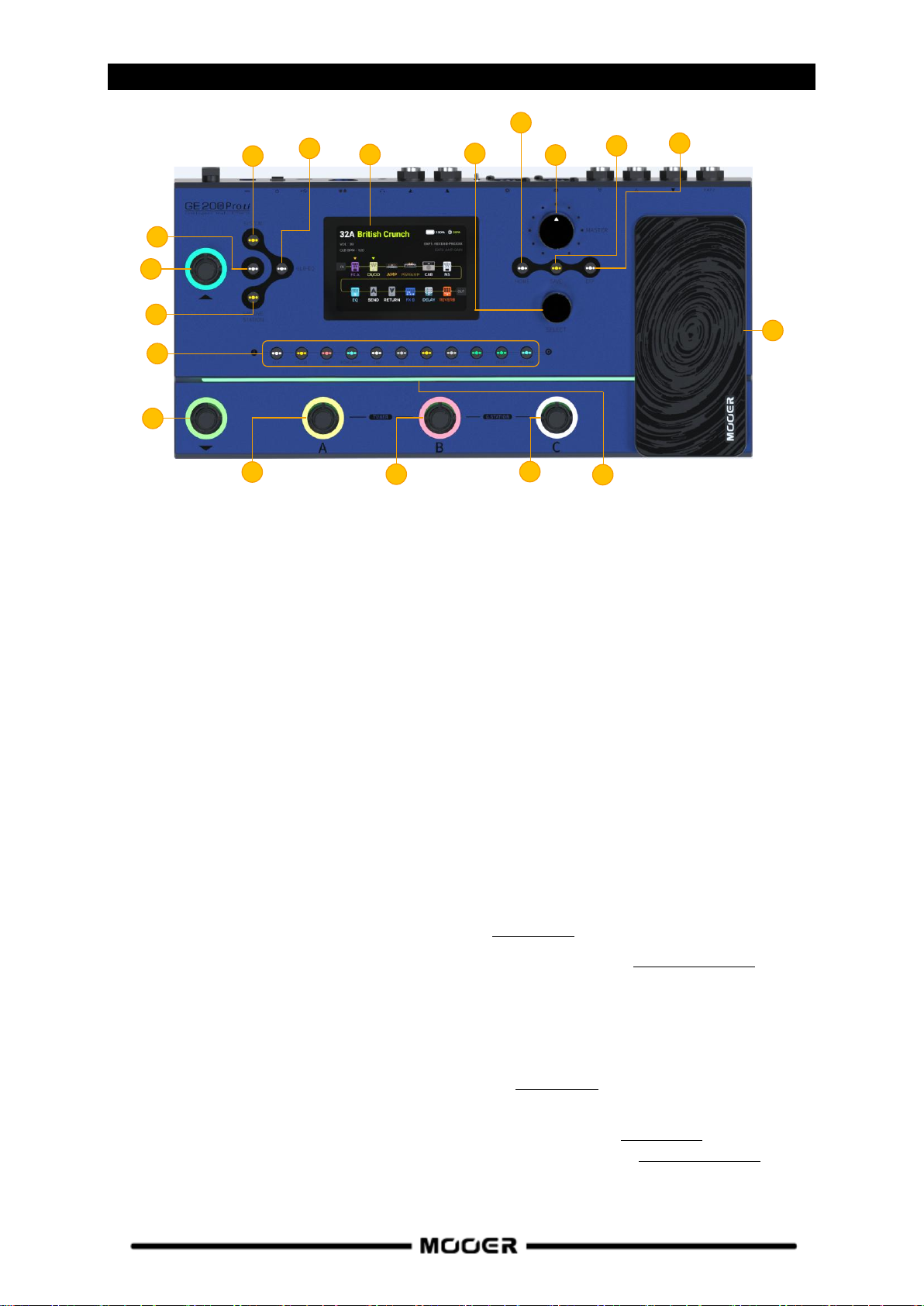
CONTROLS
1
2
3
4
5
6
7
8
9
10
11
12
13
14
15
16
18
17
1. 3.5 inch color LCD screen: Status and information about presets and operating modes.
2. Master knob: Rotate to adjust the total output volume.
3. Select knob: Use to select presets, move modules or edit parameters.
Rotate the knob to select items on the screen (highlighted).
Press the knob to confirm the selection.
Rotate the knob to change values.
Press the knob to confirm the changes and return to selection mode.
4. Home button: Press to return to the main user interface or to switch between Preset View and
Effect Chain View.
5. Save button: Press to save your settings in a Preset.
6. EXP button: Press to open the menu for expression pedal settings.
If this button is lit, the on-board EXP1 pedal works as an expression pedal to control module
parameters. If it is not lit, the EXP1 pedal can work as a volume pedal, if so configured in the EXP
menu.
7. SYSTEM button: Press to open the SYSTEM settings menu.
8. GLB-EQ button: Press to open the menu for the global equalizer settings.
9. CTRL button: Press to activate the CTRL Mode (see CTRL MODE).
10. GROOVE STATION button: Press to open the Groove Station Mode (see GROOVE STATION).
11. Effect module LED buttons: The buttons correspond to the effect modules used in the effect
chain. Press a button to open the parameter editing screen for the corresponding module. Press
again to activate / deactivate the module.
12. Bank ▲footswitch: Press to scroll up between preset banks.
This switch is also used for exiting the CTRL mode (see CTRL MODE).
13. Bank ▼footswitch: Press to scroll down between preset banks.
This switch can also be assigned a control function in CTRL mode (see CTRL MODE).
- in Groove Station mode: Looper REC / PLAY / DUB / UNDO / REDO (see GROOVE STATION).
14. Footswitch A:
- in Preset mode: switches to Preset A in the selected bank
3

- press again to enter CTRL mode
1
2
3
4
5
6
7
8
9
10
11
12
- in CTRL mode: executes pre-programmed control function (see CTRL MODE).
- in Groove Station mode: Looper Stop / Delete (see GROOVE STATION).
15. Footswitch B:
- in Preset Mode: switches to Preset B in the selected bank
- press again to enter CTRL mode
- in CTRL mode: executes pre-programmed control function (see CTRL MODE).
- in Groove Station mode: Tap Tempo control for Drum Machine BPM (see GROOVE STATION).
16. Footswitch C:
- in Preset mode: switches to Preset C in the selected bank
- press again to enter CTRL mode
- in CTRL mode: executes pre-programmed control function (see CTRL MODE).
- in Groove Station mode: starts /stops the Drum Machine (see GROOVE STATION).
Footswitches A + B simultaneously: Hold both footswitches to open Tuner mode (see Tuner).
Tap any footswitch to exit Tuner mode.
Footswitches B + C simultaneously: Hold both footswitches to open Groove Station Mode (see
GROOVE STATION).
17. EXP1 pedal: Can be configured as volume or expression pedal (e.g. Wah) (see Expression Pedal).
If properly configured, the pedal function can be switched between VOLUME and EXPRESSION
control by pressing the TOE SWITCH (pressing on the front of the closed pedal.)
18. Ambient light strip: LED light strip with programmable display modes and color combinations
(GE200 Pro Li only). Can be configured in the SYSTEM menu.
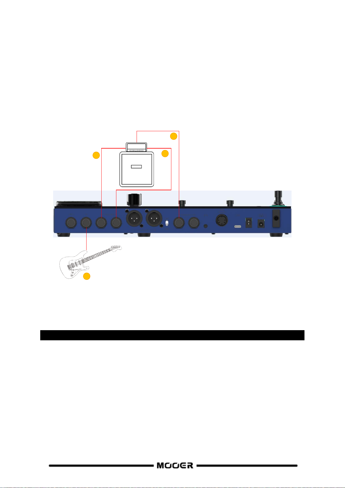
CONNECTIONS
1. EXP2: 1/4" stereo TRS jack for connecting an external expression pedal (please use a TRS stereo
audio cable).
2. INPUT: 1/4" mono audio jack, input for your instrument.
3. FX LOOP SEND: 1/4" mono audio jack, connection to the input of external effects.
4. FX LOOP RETURN: 1/4" mono audio jack, connection from the output of external effects.
5. XLR output connectors (left/right): Balanced output signal for monitor systems, sound card,
mixing consoles or similar equipment.
6. GND / LIFT switch: Ground switch. Try using this switch if you experience low frequency hum.
Flipping this switch to the opposite position may help solving ground loop problems.
7. OUTPUT jacks (left / right): 1/4" mono audio jacks (unbalanced). Connection to the input of
active speakers, other effects, amplifiers or other audio devices.
8. Phones: 1/8" stereo headphone output jack
9. MIDI IN/OUT: 5-PIN MIDI connector. Use a 5-PIN MIDI cable to connect to an external device that
can control the GE200 Pro or a device that can be controlled by the GE200 Pro.
4

10. USB Type C interface: Connection to a computer for USB audio functions or to use supported
1
4
2
3
software (see USB Audio, see MOOER Studio).
11. Power switch: Use this switch to turn the device ON / OFF
12. DC 9 V power input: Connect the supplied power supply adaptor.
CONNECTION SCENARIOS
Connection to Full-Range equipment
This connection scenario includes full-range equipment such as studio monitors, sound cards, active
stage monitors, PA systems (full-range/crossover amplifiers + full-range/crossover speakers),
headphones, and other full-range equipment. When you establish connections using this application
scenario it is recommended to activate AMP and CAB modules in order to achieve a professional
guitar sound.
1. Connect an instrument.
2. Connect a mixing console, active stage monitor, or PA system.
3. Connect a sound card or studio monitor.
4. Connect headphones.
5

Connection to a guitar power amplifier and cabinet
1
2
1
3
2
This connection scenario includes a guitar amplifier with FX LOOP or a pure power amp. It is
recommended to activate the AMP (preamp) module when you establish connections using this
application scenario. All preamp functions will be performed by the GE200 PRO in this case.
1. Connect an instrument.
2. Connect to the RETURN jack of a guitar amplifier or to the input of a power amp.
Mixed full-range / non-full-range device connection
This connection combines the two scenarios above, when you need to use full-range equipment (e.g.
mixers) and non-full-range equipment (e.g. guitar amps and cabinets) at the same time. Please refer
to the following diagram for connections and activate CAB SIM THRU in System settings (see SYSTEM
settings).
1. Connect an instrument.
2. Connect your full-range equipment.
3. Connect you non-FR equipment.
6
Four-Wire connection
1
2
3
4
The GE200 Pro supports connections to a guitar amp equipped with an FX LOOP using the
"4-wire method". This way, the preamp section of a physical amp can be positioned in the effect
chain of the GE200 Pro using the Send / Return modules and the output of the GE200 Pro can then
be run through the power amp section of the same amplifier. Please refer to the following diagram
for connections:
1. Activate the FX LOOP module and set the mode to SERIAL.
2. Turn AMP and CAB modules off to avoid interference with the pre-amp and the cabinet of the
physical guitar amp.
3. In the effect chain: select the module(s) that are supposed to act before the preamp section of
your guitar amp and move them before the SEND module using the SELECT knob (Pre modules).
Move Post modules behind the RETURN module to have them act after the preamp.
1. Connect an instrument.
2. Connect to the INPUT of your guitar amp.
3. Connect to the SEND jack of your guitar amp.
4. Connect to the RETURN jack of your guitar amp.
QUICK START
Start up
Connect the inputs and outputs of the device as required according to the connection
scenarios above.
Turn the MASTER volume knob down to minimize the output volume.
Connect the included power supply (the GE200 Pro Li can operate on battery power) and
turn the device on by switching the Power switch to "I".
The display shows a boot-up screen for a few seconds.
After the boot sequence is completed and the screen shows the main user interface, adjust
MASTER volume to the appropriate volume.
7

Main user interface
1
3 4
5
6
2
7
The GE200 PRO comes with two types of main interfaces: the Preset View and the Effect Chain View.
Use the HOME button to switch between the two views.
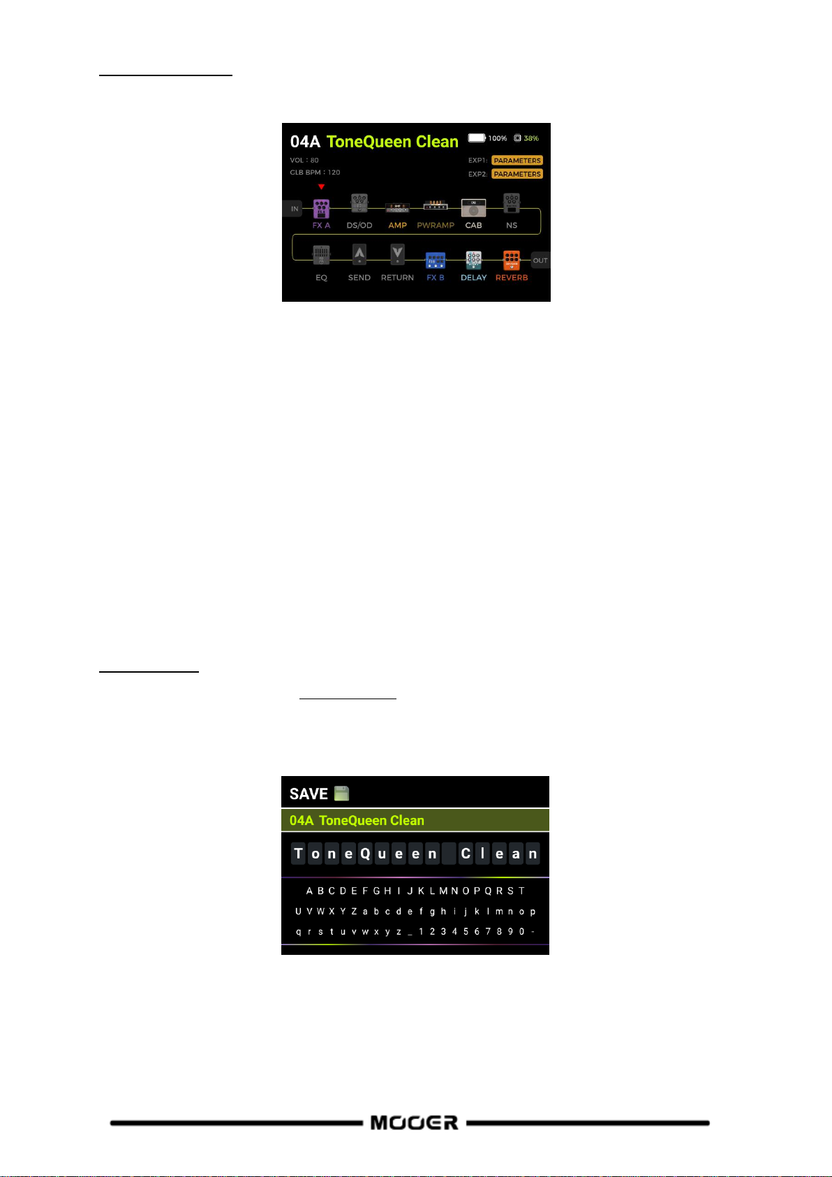
Preset view
1. Number and name of the currently active preset. The number indicates the bank (1 - 85) and the
letter behind it indicates the preset within the bank (A -C). The name can be customized during
the SAVE process.
2. CAB SIM THRU: indicates whether CAB SIM THRU is active for the 1/4" and phones outputs (CAB
and AMP modules are not effective for these outputs). This setting can be selected in the SYSTEM
menu (see SYSTEM settings).
3. Preset Volume: Indicates the output volume of the selected preset. This can be adjusted using
the SELECT knob. Press to select, then turn to adjust (0 - 100). This function is convenient for
quickly adjusting the volume balance between presets.
Note: The preset volume only affects the output level of the current preset in comparison to
other presets. Use the MASTER knob to control the output level of all presets simultaneously.
4. BPM Tempo: Indicates the current BPM tempo (Beats per Minute). This can be adjusted using the
SELECT knob. Press to select, then turn to adjust (40 - 260 BPM). The tempo can also be adjusted
using the Tap Tempo feature (see CTRL MODE).
- GLB indicates global tempo settings in BPM.
- PRE indicates individual tempo settings for each preset.
This setting can be selected in the SYSTEM menu.
Some effects of the GE200 PRO such as DELAY and MOD modules have a "Tempo Sync"
parameter which can be turned on to sync this module with the BPM tempo shown here.
(GE200 Pro Li only) (see Battery).
6. DSP utilization: indicates the calculated DSP utilization for the current preset.
This represents the DSP (Digital Signal Processing) resources used by the modules in this effect
chain configuration. Depending on their complexity and the selected effect model within the
module, some modules may require more DSP resources than others. Avoid using close to 100 %
5. Battery indicator: indicates the current charge status of the integrated Li-Ion battery
DSP resources or you may experience sound clipping due to transient overload conditions.
8

7. Pedal information: indicates the currently selected functions for the expression pedal(s) for the
current preset.
EXP1 is the integrated pedal
EXP2 is the external pedal connected to the EXP jack.
When PARAMETERS is shown, the respective Pedal works as expression pedal.
When VOLUME is shown, the pedal works as Volume pedal.
When ---------- is shown, the pedal is not configured.
Effect Chain view
The elements in the upper screen section are similar to the Preset View. Volume and BPM cannot be
adjusted with the SELECT knob in this view.
The lower area shows the effect chain, the type and ON/OFF status of the individual modules
(gray= off / color= on) and sequence of the modules. The SELECT knob can be used to select and
move modules.
Preset selection
The active preset is indicated by the number / name on the screen and by the illuminated LED ring
around the corresponding footswitch.
There are several ways to select a preset after the pedal has powered up:
1. In Preset View: rotate the SELECT knob to change presets. If name/number of the preset are not
highlighted, press the SELECT knob until they are before you rotate.
2. In Preset View or Effect Chain View: Press one of the A / B / C footswitches to select a preset in
the current bank.
Bank Switching: Step on the ▲/▼switches to open the bank selection view and switch banks.
Step repeatedly on the ▲/▼ switches to scroll through the banks or select a bank by rotating the
SELECT knob.
Then select one of the A / B / C footswitches to select a preset.
9

Shut down
The GE200 Pro is turned off by switching the Power switch on the back to "0".
Note for the GE200 PRO Li: If the power cable is still connected after shutdown, the screen will show
a dimmed graphic to indicate the battery charging status.
OPERATION
Preset editing
Effect module buttons
The row of effect module buttons below the display indicates the ON/Off status of the individual
effect modules in the current preset. When an effect module is on, the button is lit; when it is off, the
module button is unlit. The buttons are labeled with the effect module types used in the effect chain
such as AMP (amp models), CAB (cabinet simulation models), REVERB (reverb models) and so on.
FXA and FXB are modules that can contain different kinds of effect models.
The sequence of the buttons does not represent the actual sequence of modules in the effect chain.
Press a module button to turn the module on and open the parameter screen of the module.
The module button LED is now lit to indicate that the respective module is active.
Press the module button again to turn the module off.
Press the HOME button to return to the main view.
If you want to turn off an effect module from any other view, you need to press the module
button once to access the module screen and again to turn the module off.
Note: Switching between active modules will only switch between their respective parameter views.
It will not change the ON/OFF status of the module.
Parameter editing
Press the button of the effect module you want to adjust in order to open the parameter editing
interface of this module.
The ON/OFF status of the module is indicated by the color of the image (colored = ON / gray = OFF).
The ON / OFF status can be changed by pressing the module button again.
Turn the SELECT knob to move the cursor to select the item you want to adjust and then press
SELECT to confirm the selection. The selected item is highlighted with a green background.
Rotate the SELECT knob to adjust a parameter value, change a parameter status or to select a
different effect model, depending on the kind of item you have selected.
For most effect modules you can select different types of effect models (e.g. "Room" or "Shimmer"
models for the REVERB module). The model is shown in text field on top of the screen. Different
available parameters are shown below, depending on your selection (shown as rotary fields). The
10
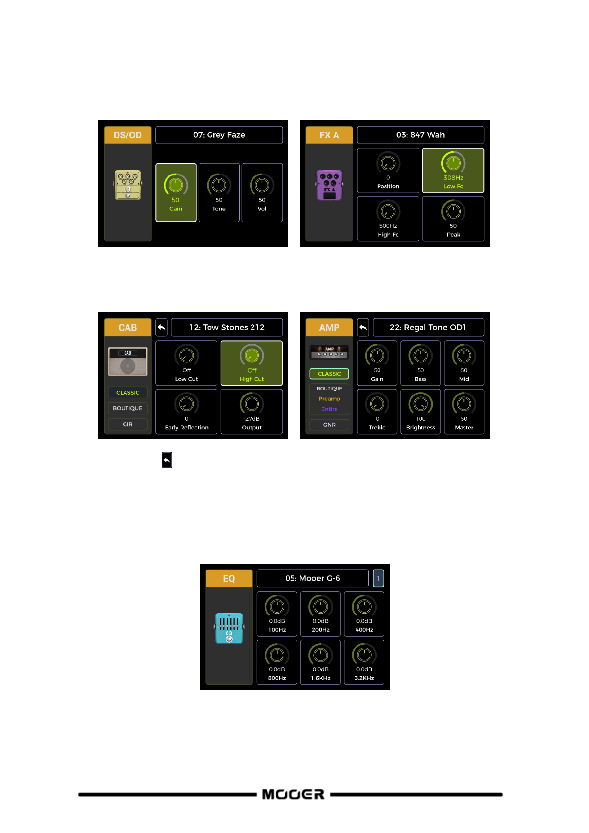
parameter settings are shown as numerical values and indicated graphically. Some parameters are
ON/OFF parameters that can be toggled by selecting them and the rotating the SELECT knob.
After completing your adjustments, press the SELECT knob again to unselect the item and rotate it to
select the next item.
The parameter screens for AMP and CAB modules additionally show model classification fields on the
left side. Rotate the SELECT knob to select a model class in the left area and then press the knob to
confirm the selection. The cursor will jump to the right area for model selection and parameter
editing.
Select the Back icon in the right hand area and press the SELECT knob return to the left side for
model class selection.
For some modules with more parameters than can be displayed on one page, a page number is
shown in the top right corner of the screen. When the page number icon is grayed out, no other page
needs to be accessed. When the page icon is not grayed out, you can select it and rotate the SELECT
knob to access the second page of parameters.
See Annex 1 for a list of available effect models and descriptions of the parameters.
Note: All changes must be stored in the Preset using the SAVE button, before you switch presets.
Otherwise your changes will be lost.
11
Effect chain editing
Press the HOME button on the panel to switch to the Effect Chain view.
The Effect Chain represents the sequence of effects a signal has to pass through within the GE200
PRO to get from the input to the output. Colored module icons indicate that they are ON. Gray
module icons indicate that they are OFF.
This view allows you to edit the order of the modules in the effect chain for the current preset:
Turn the SELECT knob to move the triangle icon over the module you want to move. Press the SELECT
knob to confirm the selection, the triangle icon will change color. Rotate the SELECT knob to move
the selected module in the effect chain. All other modules will be shifted to make room for the
module you are moving. Press SELECT again to confirm the new position and return to the module
selection mode.
Notes:
1. All changes to the order of the effect chain must be stored in the Preset using the SAVE button,
before you switch presets. Otherwise your changes will be lost.
2. When the CAB SIM THRU is activated in the SYSTEM settings, the PWRAMP and CAB modules will
be placed at the end of the effects chain by default and cannot be moved.
Saving presets
Note: If you switch presets (see Preset selection ) without saving your settings first, all changes will
be lost and the preset will return to the previously saved settings the next time you select it.
After adjusting all necessary settings, press the SAVE button to open the SAVE screen.
Turn the SELECT knob to select the Preset storage position indicated by the preset number.
The number indicates the bank (1 - 85) and the letter (A - C) indicates the preset position within the
bank. The 3 presets in each bank can be selected with the A, B or C footswitches. Press SELECT to
confirm the position and jump to the name character selection.
12
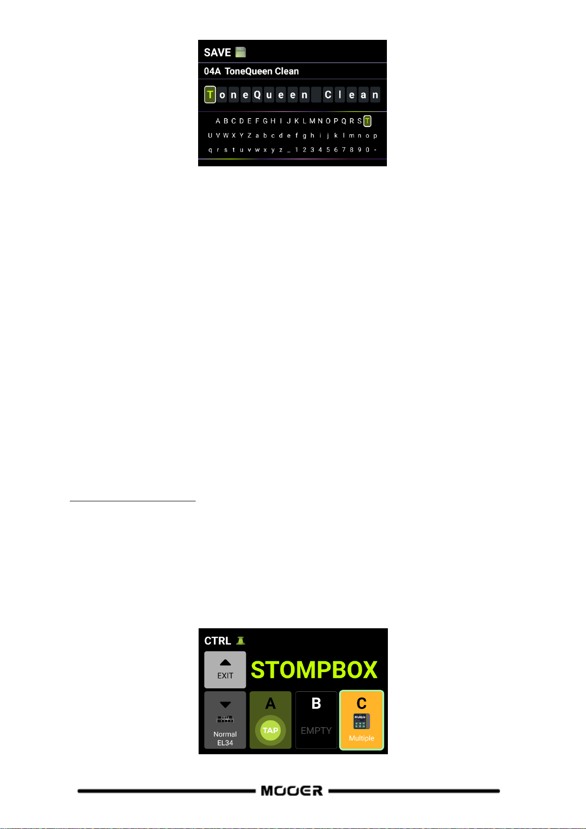
Turn and press SELECT to select the character position to be written, turn SELECT to select the
specific character for the current position, press again to confirm the character and return to the
character position selection.
When editing is complete press the SAVE button to finish saving the preset. Pressing any key other
than SAVE or SELECT will cancel the saving process.
CTRL Mode
The CTRL (control) mode is a footswitch mode based on the currently selected preset. It can be used
to control modules in the effect chain of the current preset the same way you would control
stompboxes on a physical pedal board by using the ON/OFF footswitches of individual pedals.
Alternatively, one of the footswitches can be configured for Tap Tempo input to set the tempo for
Delay / Reverb effects.
The ▼, A, B and C footswitches of the GE200 PRO can each be configured to act as an ON/OFF switch
for effect modules within the current preset's effect chain or to act as a tap tempo input.
The configuration of the footswitches only affects the currently selected preset.
You can have different CTRL mode footswitch configurations for every preset.
The four footswitches in the lower row can be used to perform the selected functions for as long as
the CTRL mode is active.
Activating the CTRL mode
In normal mode, one of the A, B or C footswitches will have its LED ring illuminated to indicate the
currently active preset. Step on this footswitch to open the CTRL mode.
You can also press the CTRL button on the panel to open the CTRL mode.
You can leave the CTRL mode and return to the main interface by pressing the ▲ footswitch or
the HOME button.
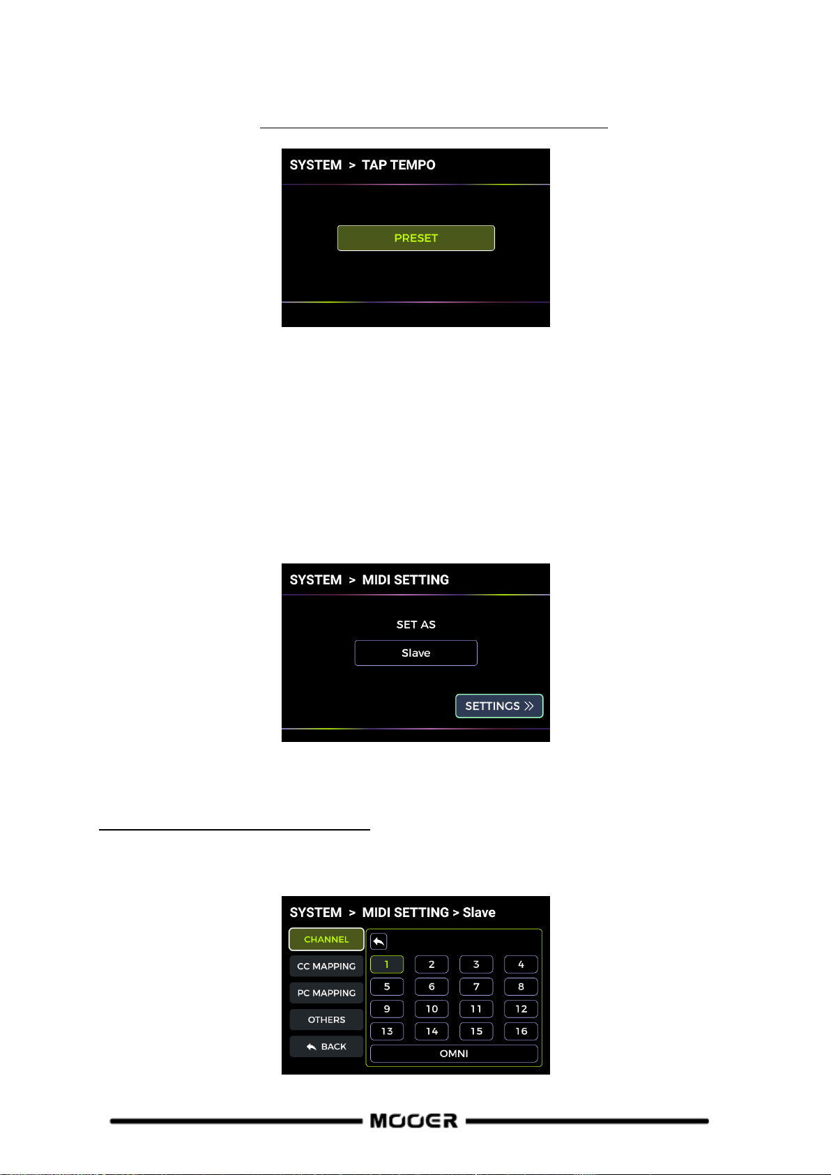
In CTRL mode, the screen displays "STOMPBOX" and a field for each of the four selectable
footswitches. A field will show EMPTY when there is no function assigned to this footswitch yet.
13

Use the ▼/A/B/C footswitches in the bottom row to execute the assigned functions. Use the
BANK ▲footswitch to exit the CTRL mode (this switch cannot be assigned to a different function).
Assigning CTRL functions
Move the cursor by turning the SELECT knob to select the footswitch you want to assign a function
to. Press SELECT to open the menu for assigning CTRL functions.
TAP:
The footswitch is assigned to perform the Tap Tempo function in CTRL mode.
The LED ring around the footswitch will blink to indicate the currently selected BPM tempo. Press the
footswitch several times to set a new tap tempo.
STOMPBOX:
The footswitch is assigned to activate/deactivate one or several modules in the effect chain of the
current preset in CTRL mode.
After selecting the STOMPBOX field, the effect chain is displayed.
Rotate the SELECT knob to select a module and press the SELECT knob to confirm selection. The
selected module will be indicated by a triangle icon above. Press SELECT again to unselect a module.
You can also select several modules, which will all be switched on/off simultaneously when the
footswitch is pressed in CTRL mode. This MULTIPLE mode supports the combination of ON and OFF
states between the controlled effect modules. This means that modules that were OFF before
switching will be turned ON and modules that were ON before switching will be turned OFF.
After completing the module selection, select DONE at the bottom and press SELECT to return to the
CTRL mode view. The name of the selected module is indicated in the footswitch field. If you have
selected multiple modules, the field will show "Multiple" instead of a name.
You can now activate/deactivate the selected module(s) by pressing the footswitch. The module(s)
will be active when the footswitch LED is lit and the footswitch field in the screen is shown in color.
The module(s) will be turned off when the footswitch LED is off and the footswitch field is shown in
gray.
14

In MULTIPLE mode, with active modules in both switching states, the field will always be shown in
color and the LED will always be on, but the field and the footswitch LED will change colors to
indicate the different states.
You can tell which modules are active in each switching state by looking at the row of module
buttons. Active modules will have their LED buttons lit.
RENAME:
You can assign an easily recognizable name to each footswitch field to make selection easier on
stage. This name will only be used in the footswitch field in CTRL mode.
Select RENAME to change the name shown in the footswitch field. Pressing SELECT opens the
rename menu:
Turn the SELECT knob to select the character position to be written, press the SELECT knob to select
the current character position and turn SELECT to select the specific character at the current
position, press again to confirm the character and return to the character position selection.
When editing is complete, press the SAVE button on the panel to complete the renaming and return
to the CTRL mode view. Pressing any key other than SAVE will cancel the renaming process.
CLEAR:
Clears the function currently assigned to the footswitch in CTRL mode and returns the field to
"EMPTY".
BACK:
Closes the assignment menu and returns to CTRL mode view without changing any assignments.
Note: CTRL footswitch assignments must be manually saved into a preset. If you switch presets
before you save the current preset, your CTRL assignments for the current preset will be lost (see
Saving).
15

Expression Pedal
The GE200 PRO supports two expression pedals:
EXP1 is the on-board rocker pedal that can be used as volume pedal (default) or as an expression
pedal to control multiple modules and parameters.
EXP2 is an external expression pedal that can be connected to the GE200 PRO using a 1/4" TRS cable
on the EXP jack on the rear panel.
All settings such as the parameter assignments, the use as volume/expression pedal or the toe
switch mappings are different for each preset and must be saved with the preset.
Press the EXP button on the panel to open the pedal setup menu.
Calibration
You need to calibrate the GE200 PRO's pedals before you use them for the first time. Calibration also
needs to be carried out when you switch external pedals of if you experience erratic pedal function.
The calibration is global and does not have to be repeated for each preset.
Use the SELECT knob to select the CALIBRATE field on the left side. The cursor will jump to the right
side.
In the top field, select EXP1 (on-board pedal) or EXP2 (external pedal) for calibration by turning and
pressing the SELECT knob.
Follow the on-screen instructions or the following steps:
Open the pedal fully and select and press NEXT with the SELECT knob.
Close the pedal fully and select and press NEXT with the SELECT knob.
Push down at the tip of the pedal to calibrate the toe switch and press NEXT with the SELECT
knob. (This calibration step is not required for external pedals = EXP2).
Note: The amount of force used to press the pedal down in this step determines the force threshold
for the expression pedal's toe switch function.
16

It is recommended that you use your foot and apply the same pressure you would use when playing
on stage.
It is important to note that the force used in this step needs to be significantly different from the
force with which the pedal was closed in the previous step. If the difference in force between the
two steps is not large enough, the screen will show a calibration error and the calibration must be
repeated. A successful calibration is indicated by a checkmark in a green circle.
Expression parameter mapping
The expression pedals can be mapped to control several effect parameters of the same or different
effect modules simultaneously.
All mappings affect only the current preset and must be stored with the preset. Save your preset
after mapping parameters before you switch presets.
On the panel: press the module button of the module you want to control with the effect pedal to
open the parameter screen for this module.
Use the SELECT knob to select the parameter you want to control.
Long press the SELECT knob until the EXP menu opens.
Select the expression pedal you want to use for controlling this parameter (EXP1 = on-board /
EXP2 = external) and press SELECT to open the parameter range menu.
Set the desired parameter values (in percent) for the closed and open positions of the pedal (e.g.
"100" and "0" for normal operation or "0" and "100" for reverse operation, or any value in
17

between). When the setting is finished, select Back at the bottom and press SELECT to return to
the previous menu.
When EXP1 or EXP2 has been set, the Delete icon on the right will light up. Selecting the icon
and pressing SELECT will clear the respective assignment.
Back: Exit the menu and return to the module parameter view.
Note: Parameters mapped to an expression pedal will have their name highlighted in blue to
distinguish them from regular parameters. You can still adjust them manually, but as soon as you use
the expression pedal, the manual setting will be overwritten by the expression pedal input.
Multiple parameter control: You can perform the steps above for several parameters of several
modules and assign them all to the same EXP pedal.
After you have finished assigning parameters to the EXP pedal, press the EXP button on the panel to
open the EXP Settings view. In the right area of the PARAMETERS section, you can now browse
through all assigned parameters:
Select EXP1 or EXP2 with the SELECT knob.
Select the parameter field, press the SELECT knob and rotate it to navigate through all assigned
parameters for the current pedal.
Select the Delete icon and press SELECT to delete the currently selected parameter
assignment.
The lower area allows you to set the MIN and MAX pedal position parameter value for the
currently selected parameter.
Use the return icon to return to the left side of the screen to access other settings.
Save your preset after mapping parameters before you switch presets.
18

Use as volume pedal
The GE200 Pro's built-in pedal can be configured as a volume pedal.
Select the EXP VOL option in the pedal settings screen and activate the EXP VOL PEDAL function on
the right. Adjust the volume level mapped to the minimum and maximum pedal positions.
This setting will be saved for each individual preset.
Use the return icon to return to the left side of the screen to access other settings.
Once the settings are complete, the output volume level of the GE200 Pro can be controlled by
stepping on the on-board pedal in volume pedal mode.
Note: The on-board pedal can be switched between Expression Pedal Mode and Volume Pedal
Mode by pressing on the front of the closed pedal (toe switch).
When the EXP button LED is on, the pedal works in Expression Pedal Mode, when it is off, the pedal
works Volume Pedal Mode. The pedal function is also indicated in the main view (see Main user
interface).
Toe switch mapping
In addition to switching the pedal function between volume and expression control, the toe switch
on the front end of the pedal can also be mapped to switch modules within the preset's effect chain
ON/OFF.
Example of an application scenario:
The expression pedal parameter is mapped to the WAH sweep frequency and the toe switch is
mapped to activate/deactivate the WAH module. This simulates the functions of an actual WAH
pedal.
The toe switch function can be mapped to an effect module as follows:
Open the EXP settings view.
Select TOE SWITCH on the left side.
Select the + field on the right side.
Select the desired module from the effect chain. The selected module is marked with a triangle
icon.
19

Select DONE and press SELECT to confirm your selection.
Flat
In tune
Sharp
You can use the same method to add more effect modules to be simultaneously switched by the toe
switch. They will all be listed in the right area of the TOE SWITCH section in the EXP settings view.
If you want to remove a toe switch mapping, simply select the delete icon next to the
corresponding module in the list.
TUNER
Hold footswitches A and B down simultaneously until the Tuner view opens.
Tuner screen
Select BYPASS with the SELECT knob to set the tuning mode to BYPASS or MUTE.
BYPASS tuning disables the internal effects and sends a clean signal to the outputs for as long as the
tuning mode is active.
MUTE tuning mutes the outputs for as long as the tuning mode is active.
Select 440Hz with the SELECT knob to adjust the tuning reference frequency. You can select a
reference frequency from a range between 430 Hz - 450 Hz. The default value is A = 440 Hz.
Tuning
Open the tuning screen.
Pluck the open strings of your guitar. The screen will display the current note and the pitch.
Tune your guitar until the pointer on the screen is in the center position.
Exit tuning mode
Use any of the following methods to exit the tuning mode:
Press any footswitch once.
Hold footswitches A + B down simultaneously.
Press any button.
20

GROOVE STATION
The Groove Station combines drum machine and phrase looper functions. You can use these features
independently or in combination. Synchronization is supported, when Drum Machine and Looper are
used at the same time.
Open the Groove Station
There are two ways to open the Groove Station mode:
Press the Groove Station button on the panel.
Press footswitches B and C down simultaneously until the Groove Station screen opens.
The five large square fields in the Groove Station screen indicate the footswitch functions.
The progress bar at the top indicates the recorded time as well as the current status and the position
of the phrase loop during playback.
Volume sliders
The fields for LOOPER and DRUM indicate the respective output volumes and can be controlled by
selecting them with the SELECT knob and then rotating the SELECT knob. The number in the slider
indicates the volume in percent.
Drum Machine
Navigate to the fields on the right side of the screen to select the Style (e.g. FUNK, POP, ROCK …
METRONOME) for the drum machine and also one of 10 Rhythm Patterns (e.g. 4/4, 6/8 ….).
Footswitch B: DRUM TAP
Press B several times to tap in the desired tempo for the drum machine. The selected tempo
is indicated graphically and numerically in the BPM bar in the center of the GROOVE STATION
screen. You can also select the BPM bar to set value using the SELECT knob.
If the drum machine is ON, the tempo will also be indicated by the flashing LED ring of
footswitch B.
Footswitch C: DRUM ON / DRUM OFF
Press C to start / stop the Drum Machine.
Phrase Looper
The GE200 PRO features a Looper with up to 60 seconds of recording time, overdubbing function and
independent level control.
21

The ▼ and A fields indicate the functions that will be performed when the corresponding
footswitch is pressed the next time.
Footswitch ▼: REC / PLAY / DUB / UNDO / REDO
Press once for Record, tap again for Play, tap again for Dub…
Hold for Undo, hold again for Redo (after recording more than one layer of Looper track)
Footswitch LED indication for ▼:
Solid Red: Recording mode
Solid Blue: Playback mode
Solid Purple: Overdub mode
Footswitch A: STOP / DELETE
Press once to stop playback/recording
Hold to delete the entire recording
Footswitch LED indication for A:
Blinking green: the Looper is in Stop mode
Solid blue: all recordings have been deleted
Off: recording or playback in progress
Looper Auto Record
The Looper is able to start recording automatically as soon as the input signal triggers the threshold.
Activate AUTO REC by selecting the AUTO REC field with the SELECT knob, press select and adjust
the appropriate trigger threshold and press SELECT again to confirm. Setting the threshold to "0"
turns AUTO REC off.
With automatic recording active, pressing footswitch ▼ will activate the standby function and the
recording will start as soon as the input signal increases above the threshold.
When Auto Record is not active, the recording starts immediately with pressing ▼.
Drum synchronization
Activate DRUM SYNC to synchronize the Looper function with the Drum Machine when both
features are to be used at the same time. This way, they will both be in synch with regard to the bar
structure.
Pick the style and rhythm pattern for the Drum Machine first, and set the desired tempo.
Activate DRUM SYNC by selecting the field with the SELECT knob and rotating it until DRUM
SYNC ON is indicated.
Execute "REC" for the Looper (Footswitch ▼).
22

A one-bar count-in will be played, based on the selected rhythm pattern.
Recording will begin after the count-in, and the Drum Machine will be synchronized.
To ensure proper synchronization between the two features, at the end of the first layer of recording
(in "Play" mode) and after the Looper has reached an integer number of measures, the remaining
part of the phrase loop that is less than one measure will be processed in 1/2 bars: less than 1/2 bar
will be trimmed, and if it exceeds 1/2 bar, playback will be delayed until it reaches a full bar.
Take a 4/4 beat as an example: When you record to the third beat of the fourth bar, playback will be
executed (more than 1/2 bar), the LOOPER will record the fourth full bar and then switch to
playback. The length of the loop is 4 full bars.
If playback is executed when the recording of the fourth bar ends on beat 1 (less than 1/2 bar), the
LOOPER will discard the extra content of the fourth bar and immediately start playback from the
beginning, and the length of the loop will be 3 full bars.
Close the Groove Station
Use any of the following methods to exit the Groove Station Mode:
Press the BANK ▲ footswitch.
Press footswitches B + C simultaneously.
Press the HOME button.
Note: If the Looper and/or the Drum Machine are playing when you leave the Groove station view,
they will continue playing. You need to re-open the Groove Station view in order to stop the Looper
and/or the Drum Machine.
GLOBAL EQ
GLB-EQ is a global equalization setting for the 1/4", XLR and headphone outputs, which is convenient
for quickly adjusting the sound to the requirements of different venues and the frequency response
characteristics of different amplification equipment. This is the best way to avoid tedious preset-bypreset adjustments.
Press the GLB-EQ button on the panel to enter the Global EQ menu. Use the SELECT knob to select
the output to be enabled for global equalization (1/4" & headphone output or XLR). The XLR output
can be enabled independently and can have independent parameter settings.
Use the SELECT knob to activate / deactivate the Global EQ for the selected output with the ON/OFF
parameter (lower right corner) and then adjust the frequencies, high-cut and low-cut settings.
The GLB-EQ button on the panel will light up when any part of the global equalization system is
turned on.
23

SYSTEM SETTINGS
The global SYSTEM SETTINGS screen can be accessed by pressing the SYSTEM button on the panel.
Selections and Changes are made with the SELECT knob.
Screen Brightness
In some situations, you may want to adjust the screen brightness to adapt to different lighting
environments, or to extend the battery life of the battery version.
Input Level
Use this setting to adjust the global input volume of the GE200 Pro according to the output power
level of the currently used instrument. The adjustment range is -45 dB to 6 dB. This setting only
affects the instrument input, not the incoming signal over Bluetooth Audio or USB audio.
Note: Adjusting the global input level can prevent input distortion caused by exceedingly powerful
input signals.
24
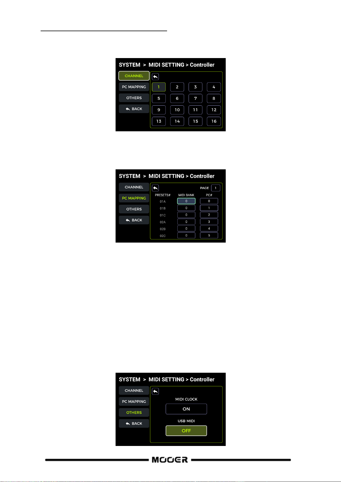
Tap Tempo
The GLOBAL and PRESET options in this screen can be used to determine which presets the selected
BPM tempo is applied to. Please make this choice before you change the tempo!
If PRESET is selected, any tempo change is only effective for the current preset, and other presets
can have different tempos. You need to save your preset before switching to another preset.
If GLOBAL is selected, the tempo change applies to all presets, and all other presets will be set to the
currently displayed value. Global BPM changes do not have to be saved and will overwrite all
individual BPM settings for other presets.
MIDI Setting
The GE200 Pro is configured with a 5-pin MIDI interface and can be defined as a transmitter
(Controller) or receiver (Slave).
Use the SELECT knob to select the device as CONTROLLER or SLAVE. Then select the SETTINGS field
and press SELECT to open the corresponding configuration menu.
GE200 PRO as controlled device (Slave)
After selecting the GE200 PRO to act as a MIDI slave, the following options are provided:
MIDI Channel
25

Select CHANNEL and select the MIDI command channel that the GE200 PRO is supposed to respond
to. The factory default is channel 1. OMNI means the GE200 PRO will ignore the channel information
and respond to the command directly. This simply means that no matter what channel is set by the
transmitting device, the GE200 PRO will respond to the corresponding MIDI command.
CC Mapping
Select the PAGE number in this list to page through all pages of CC code.
Select the FUNCTIONS fields to set the function responding to the respective CC code.
PC Mapping
Select the PAGE number in this list to page through all pages of PC code.
This list corresponds to the preset numbers that can be controlled by PC codes. The individual
settings can be changed by the user.
Other settings
Use this page to activate/disable MIDI CLOCK SYNC for incoming MIDI commands and to
activate/disable USB MIDI.
MIDI Clock: When active, BPM tempo-based features of main interface will be synchronized to the
MIDI clock commands received from an external device.
USB MIDI: Enable this feature to receive MIDI commands from a computer through the USB-C
interface.
BACK
Exits the screen to return to the MIDI SETTINGS setup screen.
26
GE200 PRO as controlling device (Controller)
After selecting the GE200 PRO as a MIDI controller, the following options are provided:
MIDI Channel
Select CHANNEL and select the MIDI command channel that the GE200 PRO will use to send
commands. The factory default is channel 1.
PC Mapping
Select the PAGE number in this list to page through all pages of PC code.
Select the MIDI BANK to be used for the current preset number.
Select the PC code number to be used for the current preset number.
After switching to a preset, the GE200 PRO will send MIDI bank information + PC command to the
receiving device.
Other settings
Use this page to activate/disable MIDI CLOCK SYNC for incoming MIDI commands and to
activate/disable USB MIDI.
MIDI Clock: When this is active in Controller mode, the current BPM setting the GE200 Pro will be
sent out as MIDI clock command.
USB MIDI: Enable this feature in Controller mode to send out MIDI commands through the USB-C
interface.
27

BACK
Exits the screen to return to the MIDI SETTINGS setup screen.
CAB SIM TRHU
This setting is used for the 1/4"and headphone outputs to globally bypass all power amp and
cabinet simulation modules in all presets.
When this function is enabled, the power amp and cabinet simulation modules will automatically be
moved to the end of the effect chain and cannot be moved using the SELECT knob.
This may be necessary for certain connection scenarios where different outputs with or without
cabinet simulation (or amp simulation) are used. See section Connection Scenarios for details.
Spill-Over (Effect Trails)
The GE200 PRO supports the trail hold function for delay and reverb effects.
Under some conditions, the natural decay of delay repeats or reverb echoes can be maintained when
a corresponding module in is toggled on/off within a preset or when a different preset is activated:
Trails when switching presets:
This type of switching is accomplished by using the BANK, A, B or C footswitches or external MIDI
commands to change presets.
Find SPILL-OVER in the SYSTEM SETTINGS and activate it.
Copy a target preset and save it to the position you want to switch to.
In the new preset position, you can change the module switching status, or adjust different
parameter settings according to the sound requirements.
After completing these settings, you can switch between these two presets and maintain the
natural decay of the delay and reverb tails.
Note: The trails feature does not support switching between two different effect chain
configurations or selecting different delay and reverb effect models.
28

Trails when modules are switched ON/OFF within a preset:
This type of ON/OFF switching while playing is usually accomplished using the CTRL mode, the EXP1
toe switch or a MIDI command from an external controller (see Toe Switch mapping for the EXP1
pedal, CTRL Mode or MIDI.)
Open the parameter editing menu of the delay or reverb module in the preset.
Find the "Trail" parameter and activate it.
USB AUDIO
The GE200 PRO supports 24-bit, 44.1 kHz, low-latency sound card functions and supports most of the
host software available for Windows and Mac systems. Windows system users need to install a
special ASIO driver to realize low latency recording/monitoring. Please visit the official website to
download the Windows ASIO sound card drivers. Mac users do not need to install the sound card
driver. The system is plug-and-play for Mac.
Usage MODE
Normal mode: You can use the GE200 PRO like an external sound card. The input will be
automatically taken from the input jack of GE200 PRO (your guitar), and the output will be sent to
the USB output port (digital signal) from the GE200 PRO to your computer.
Re-AMP mode: You can use the GE200 PRO as a sound card and at the same use the digital audio
signal processing features. The USB signal input of the GE200 PRO (digital signal received from the
computer) will automatically be used as input, and the USB output (digital audio signal) to the
computer will be used as output.
The default factory setting for the GE200 PRO is Normal.
OUTPUT mode
When using the sound card recording function, these two switches can be used to determine
whether the left and right outputs receive dry sound or processed effect sound. When "DRY" is
selected, the output signal of the currently selected channel is not processed by the effect modules.
When "WET" is selected, the output signal of the currently selected channel is processed by the
effect modules. Selecting the left and right output signals as dry or wet can be convenient to
29

preserve the dry signal for post-processing when recording. This way you can listen to the wet signal
and record the dry signal.
The default factory setting for the GE200 PRO is "WET" for both the left and right channel.
REC LEVEL
Adjust the recording level of the sound card function.
The default factory setting is 0 dB.
MIX Ratio
Adjusts the mix ratio between hard and soft monitoring.
A setting all the way to the left means that 100 % of the signal is coming from the GE200 PRO (hard
monitoring). All the way to the right means that 100 % of the signal comes from the
computer/DAW/plug-in, etc. (soft monitoring). With a center setting of 50:50, the ratio of hardware
output to USB digital input is 1:1.
The default factory setting is a 50:50 mix of hard and soft monitoring.
PLAY Level
Adjusts the volume level of the digital input of the sound card function, i.e. playback volume. The
default factory setting is 0 dB.
Mode descriptions
Normal mode
In this mode, the GE200 PRO will act as an external sound card with effects and DAW computer
software can be used for recording. The signal path of this mode is shown below:
Setup:
Set the Mode to Normal.
Open the recording software on the computer and configure it to use the GE200 PRO sound
card driver. Then set the input and output ports to "Analogue1/Analogue2" of the
GE200 PRO.
Adjust the Wet and Dry settings for the left and right channel depending on the recording /
monitoring requirements.
Record a track, and pay attention to the input level indication to make sure there is no signal
distortion (clipping) even with hard playing. If the input signal is too strong, adjust the
Recording level accordingly.
Play back the recorded track or other audio files to make sure that the return volume is
appropriate (for different monitors, such as headphones or monitors), and adjust the Play
level accordingly.
By playing the audio file through the GE200 PRO, you can balance the volume ratio between
the recorded audio and the live signal by adjusting the Mix Ratio.
Confirm the input and output levels and start recording.
30

Playback level
PC
Record level
Output
DSP effects
Re-Amp mode
The Re-Amp recording mode is a digital audio signal reprocessing method, which can be used to run
a dry signal track from a computer through the effect modules of GE200 PRO, and then record it as a
new "wet" track. The signal path of this mode is shown below:
Setup:
Open the recording software and add two tracks. One of them is a dry track that needs re-
amping (pre-recorded or other audio track), the other one should be a blank track.
Play the dry track through the GE200 PRO DSP effects and make sure the input level
indication in the PC software shows no distortion (clipping). Adjust the level with Record
level.
While playing the dry track, you can also adjust the switches and parameters in the GE200
PRO for the desired Re-Amp effect. Listen to the output and adjust the level using the Play
level control.
Select the blank track, activate the recording and play the dry track. Re-Amp is finished, when
the dry track is finished.
Note:
After starting the recording software, you should set the GE200 PRO driver as input driver in
the system settings or in the driver settings of the recording software. Also set the input and
output ports to the input and output of the GE200 PRO. Otherwise you could experience no
input, no output, excessive lag or other abnormal conditions.
We recommended that you do not try to adjust settings or operate switches on the GE200
PRO during the Re-Amp recording process, unless this is required for special effects. This may
result in undesired results.
Should you encounter too much lag, open the sound card driver control panel and adjust the
cache settings to achieve a shorter lag time.
After using the Re-Amp function, we recommend switching back to Normal mode.
Otherwise the pedal may boot up in Re-Amp mode when started the next time and there will
be no signal from the guitar input as the input would still be set to USB input.
Bluetooth Audio
The GE200 PRO supports a Bluetooth connection to play back audio material from other devices such
as Smartphones or tablets.
The audio signal coming in over Bluetooth will be mixed with the signal from your guitar so you can
use this feature for practice or to play along to an audio track.
Activate the Bluetooth function for the GE200 PRO in SYSTEM settings.
Open the Bluetooth settings of your mobile device and make sure Bluetooth is active.
Find "GE200 PRO" in the list of available devices.
Click "Connect" or "Pair" to play music through the Bluetooth input of the GE200 PRO.
Use the volume controls on your mobile device to control the input volume at the
31

GE200 PRO and thus the mix of the Bluetooth audio and the audio generated by your guitar
playing through the GE200 PRO.
Lighting
The lithium battery version of the GE200 Pro Li is equipped with a built-in RGB ambient light strip.
You can set the color and or the effect of the RGB strip using this setting.
Set the switch ON to and select the lighting mode for the ambient light strip below.
SOLID constant light
Set the ambient light strip to ALWAYS ON mode and choose the light color according to your
personal preference. Then select the BACK icon at the bottom to return to the previous menu.
SLOW FLASHING breathing light
Set the ambient light strip to SLOW FLASHING mode and choose the light color according to your
personal preference. Then select the BACK icon at the bottom to return to the previous menu.
RAINBOW WAVE
Set the ambient light strip to RAINBOW WAVE mode and choose several light colors to be included in
the rainbow according to your personal preference. Then select the BACK icon at the bottom to
return to the previous menu.
Language Selection
The GE200 PRO supports menus in Chinese and in English.
Factory reset
If required, settings can be partially or fully restored to factory values.
Use the SELECT knob to select the settings you want to re-set (highlighted in green).
Then select RESET to confirm.
Presets: Only the preset data will be restored to factory settings. All presets you may have
created, modified or imported after purchasing the GE200 PRO will be deleted.
Global Settings: Personalized settings such as screen brightness, global preferences, MIDI
mappings, USB audio settings, trails and language settings will be restored to factory
defaults.
MNRS/IRS: All imported MNRS samples as well as GIR and IR sample data will be deleted.
32

BATTERY
The GE200 Pro Li is a version of the GE200 Pro with built-in lithium battery.
Battery power information is displayed at the top of the main view when the device is on.
When the battery level drops to 20%, a pop-up window will appear on the screen to indicate that
the battery level is low and you need to plug in the power adapter for charging to prevent the
device from shutting down due to battery depletion, which may result in the loss of unsaved
settings and parameter data.
When the battery is about to run out, a pop-up window will appear on the screen to warn that the
device will shut down in a few seconds.
When you try to turn the device on with a low battery, the screen will indicate a battery warning
and the device will not boot up. You need to connect the power adapter to turn on the device in
this state.
When charging with the power adapter plugged in while the power is on, the battery icon in the
screen will display a green lightning symbol to indicate that it is charging.
When charging with the power adapter plugged in, but the device turned off, the screen will
display battery level information as shown below.
33

MOOER STUDIO SOFTWARE & GE CLOUD APP
1
2
3
4
MOOER STUDIO Software
MOOER STUDIO is the computer editor software for MOOER intelligent series products. Users can
edit effect module parameters, re-order the effect chain and also manage data (firmware updates,
upload/download presets, import of GNR/GIR/IR files, backup/restore settings).
Software download
Visit the official MOOER AUDIO website (www.mooeraudio.com) and navigate to the
SUPPORT - DOWNLOAD area. Find the "GE200 PRO" page, download the appropriate installation
program for your operating system (Windows or Mac) and install it.
System requirements:
Windows-Win10 or above
Mac OS-10.11 or above
Establishing the connection
After the installation is complete, please use the supplied USB cable to connect your GE200 PRO to
the computer, open the MOOER STUDIO software, and click on the CONNECT button to establish the
connection between the software and the device.
Data Manager interface
1. Device online information
Displays connected device, connection status, and firmware version. Click the switch to connect or
disconnect.
2. Function selection area
Select the function you want to use. You can perform firmware updates, 3rd party GIR/IR file
import, GNR file import and backup/restore all settings on your device.
3. Language selection
Click the drop-down box to select the language. This setting adjusts the language of both the
software and the connected device.
4. Function operation area
The features in the operation area depend on the selected function on the left side.
34

Firmware update
You can find the current firmware version of your GE200 Pro by opening the Factory Reset
screen in the SYSTEM menu. The firmware version is shown at the top of the screen.
Download the editor software with the new firmware version, install it, and connect your
GE200 PRO to your computer.
Find the DEVICE UPDATE button in the function selection area on the left side.
Click on UPDATE in the function operation area on the right side to confirm. The device will
be booted to update mode.
Wait for a few minutes until the update is complete.
Note: To avoid unexpected issues, please do not disconnect the USB connection and power supply
during the update process.
GIR/IR import
GIR and IR files are based on impulse response technology for cabinet simulations. The standard
format for IR files is "wav". GIR files are captured from an actual cabinet using the "GE LABS" app.
Both file types can be loaded into the empty slots of the GIR list in CAB modules in the GE200 PRO.
You can get IR files from third parties or visit www.mooerstudio.com to download GIR files to your
computer.
Select the third-party IR (3rdIRs) option on the left side of the software interface.
Select the position for the file in the list. The list corresponds to the GIR list in the CAB
module in the GE200 PRO.
Click "+" to select a file on your computer and import it into the GE200 Pro.
Click OK to import the selected GIR file.
Click "-" to delete a selected file from your GE200 Pro.
You will find the imported sample file in the GIR section of the CAB module.
GNR file import
GNR is the amp sample file based on the MNRS technology, which captures actual amplifier sound
samples via the "GE LABS" app. MOOER devices supporting MNRS files can use the files downloaded
from www.mooerstudio.com. Users can download the MNRS files to their computer, and then load
them into the device for use.
Click on GNR on the left side in the MOOER Studio software window.
Select the position for the file in the list. The list corresponds to the GNR list in the AMP
model module in the GE200 PRO.
Click "+" to select a file on your computer and import it into the GE200 Pro.
Click OK to import the selected GNR file.
Click "-" to delete a selected file from your GE200 Pro.
You will find the imported sample file in the GNR section of the AMP module.
Data backup
The backup feature allows the user to make a complete backup of the device's data, including preset
patches, loaded GNR/GIR/IR files and global settings. You can use this feature to quickly recall
settings for different usage situations and venues.
Select Backup on the left side of the MOOER Studio software interface to open a list of
previous backups.
Click on Backup and wait until the backup procedure finishes. Your backup file will be listed
with a date and time stamp.
If you need to restore the data, find the corresponding backup record and click Restore to
quickly recall a backup file into your device.
35

Preset Editor interface
2
1
3 4
5
6
8
9
7
1. Device connection status
Displays the version number, connection status and other information about the currently
connected device.
2. Preset list area
This area displays all the presets of the current device. You can use the right mouse button to
perform operations like copying and pasting, renaming, importing and exporting.
3. Preset saving area
In this area, you can edit the preset name and save it.
4. Functions and settings bar
This area allows you to set the preset volume, view and adjust the BPM tempo, set the CTRL mode
footswitch assignments, set the pedal functions, start the tuner and open the Global Setup menu.
5. Global Equalization Settings
Click on the icon to bring up the menu for global equalization settings.
6. Effect chain area
This area shows displays the effect chain of the current preset with the ON/OFF status and
sequential arrangement of the modules.
7. Effect model selection area
This area allows selection of the effect models for the selected module. Click on a model to use it
in the selected module.
8. Module ON/OFF
Use this switch to activate/deactivate the selected module.
9. Parameter adjustment area
This area allows you to adjust the parameter value of each model in the preset, and also provides
you with a function for pedal mapping.
Preset management
In the preset list area, you can click to select a preset to display information about it on the
right side. The selected preset will be simultaneously loaded in the GE200 Pro.
Right-click on a preset to open a window where you can rename/copy/paste/import/export
the preset. The exported preset file will be saved into the target file folder, click on the folder
icon at the top of the preset list to open the default folder.
36

Preset editing
The effect chain area shows the order and status of the modules for the current preset.
Parameter adjustment: Click on a module, to show the module's parameters in the area
below and you can adjust them directly using your mouse.
Changing the order: Select an effect module, hold it and drag it to the desired position.
Saving changes: When any changes have been made in a preset patch, the saving icon in the
preset saving area will flash as a reminder. After you confirm saving, the changes will be
saved.
Expression pedal settings
You can find the expression pedal options at the bottom of the parameter adjustment area. Click the
respective dot icons to assign selected parameters to the expression pedal. You can also adjust the
minimum and maximum values.
Click on the expression pedal icon in the functions and settings bar at the top to see all parameters
controlled by the expression pedal. You can edit them directly.
On the right side of the expression pedal area, you can assign the function associated with pressing
the toe switch on the pedal.
Note: The changes in the settings of the expression pedal must be saved manually into the preset
patch.
Preset volume level and BPM settings
You can adjust the preset volume level and the BPM setting in the functions and settings bar. You can
use the TAP function for BPM setting: click the TAP icon several times to input a tempo.
When the tempo parameters of a Delay module or some of the Modulation modules are set for
TEMPO SYNC, they will all sync with the TAP value you have set.
Note: In the SYSTEM settings menu, you can set the TAP tempo as global TAP input or as TAP input
for the current Preset.
SYSTEM Settings
Click on the SYSTEM settings icon to open the Systems menu. Use this menu to adjust various
globally effective systems parameters. (See section SYSTEM SETTINGS.)
37

GE CLOUD APP
GE CLOUD APP is a mobile data management application for devices of the GE Series.
Using a Bluetooth connection on your smart phone, you can upload or download presets and
import GNR/GIR sampling data from the cloud.
App download
IOS users can download the software by searching for GE CLOUD in the App Store.
Android users can download the software by searching for it in the App Store (Google Play,
App Store, etc.) or by visiting the download area of the official website of MOOER AUDIO.
System Requirements
IOS 11 or above Android 5.0 or above
Connection and Login
Make sure Bluetooth is active on your Smartphone and on your GE200 Pro (SYSTEM).
Activate Location on your Smartphone.
Open the app, swipe the picture left or right until the image of the GE200 Pro is displayed
and click the CONNECT switch. Click the device name in the pop-up menu to connect.
Login or register an account. Users who already have a MOOER STUDIO account do not
need to register again.
After connecting and logging in, you can open the MNRS section of the app to download a
large number GNR files (Amp models) or GIR files (Cab Sim models) from the cloud
directly into your GE200 Pro. You can find and use these models in the GNR sections (AMP
module) or GIR sections (CAB module) of your GE200 Pro.
Open the PRESET section of the app to find the Presets on your GE200 Pro listed under
"My Device". You can tap the Upload button to load your Preset (including a description
and a classification) into the cloud for other users to download.
The "Clouds" list in the PRESET section shows Factory and User presets to download into
your GE200 Pro. A filter feature makes selection easier. Selecting a preset shows its effect
chain configuration. You can then tap on "Download", select a storage slot on your device
and load it directly into your GE200 Pro. The downloaded preset will then be opened on
your device for immediate testing.
38

TROUBLESHOOTING
The GE200 PRO does not start
Ensure that the original power adapter is connected.
GE200 PRO Li (battery-powered version): Make sure the battery still has sufficient charge to
meet the power demands during boot-up. Connect the original adapter before trying to start
the device.
No sound after startup
Check that the MASTER volume knob on the panel is turned to the proper position.
Navigate to INPUT LEVEL in the SYSTEM settings to make sure the input gain slider is in the
proper position.
Check that the preset volume is properly set.
Check if the EXP1 pedal is in volume mode and move the pedal to the "toe down" position.
Check that USB Audio in the SYSTEM settings menu is in "Normal" mode.
"Re-AMP" mode will switch the source of the signal input to USB and cause the normal input
to be silent.
Low frequency hum
Please use signal cables with good shielding.
Change the usage environment or the time of usage to determine if the noise is caused by
interference from sources in the environment.
Keep a distance from computers, motors, fans and other electrical appliances to reduce
electromagnetic interference.
Toggle the GND / LIFT switch to eliminate ground-loop based noise.
SPECIFICATIONS
Effects
Number of module types 11
Total number of effect models 286
Preset storage slots 255
Impulse response
Supported formats WAV
Sampling rate 44.1 kHz
Sampling accuracy 24 bit
Number of sample points Up to 2048 sampling points
EXP2 jack
Interface type 1 x 1/4'' TRS stereo connector
Input impedance supports 10 - 100 kOhm expression pedals
Inputs
INPUT jack
Interface type 1 x 1/4'' unbalanced mono input connector
Input impedance 4.7 MOhm
Maximum input level 5.746 dBu
RETURN jack
Interface type 1 x 1/4'' unbalanced mono input connector
Input impedance 4.7 MOhm
Maximum input level 5.746 dBu
39

Audio Analog-to-Digital Converter
Sampling rate 44.1 kHz
Sampling accuracy 24 bit
Dynamic range 100 dB
Frequency response 20 Hz - 20 kHz, +0 / -1 dB
Outputs
OUTPUT jack
Interface type Two 1/4'' unbalanced mono output jacks
Output impedance 600 Ohm
Maximum output level 13.745 dBu
XLR connector
Interface type 2 x balanced signal XLR output jacks
Output Impedance 600 Ohm
Maximum output level 13.745 dBu
SEND jack
Interface type 1 x 1/4'' unbalanced mono output connector
Output Impedance 600 Ohm
Maximum output level 13.745 dBu
PHONES jack
Interface type 1 x 1/8'' unbalanced stereo output connector
Output impedance 32 Ohm
Maximum output level 13.745 dBu
Audio DAC
Dynamic range 100 dB
Frequency response 20 Hz - 20 kHz, +0 / -1 dB
Signal-to-noise ratio 100 dB
Misc
MIDI interface
MIDI IN or MIDI OUT 1 x 5-pin female connector
USB port
Interface type TYPE-C connector
USB Audio USB2.0, 2 in 2 out, 44.1 kHz, 24 bit
Interface type TYPE-C connector
General
Power Supply GE200 PRO: DC 9 V, 1 A, negative center
GE200 PRO Li: DC 9 V, 3 A, negative center
Battery (GE200 PRO Li) Li-ion, rechargeable, 3000 mAh, 22.2 Wh, 7.4 V
Battery life (GE200 PRO Li) Approx. 5.5 hours
Charging time (GE200 PRO Li) Approx. 2 h 10 min (using original adapter, device turned off)
Operating temperature 0 - 60°C
Dimensions 324 mm × 162 mm × 58 mm (LxWxH)
Weight GE200 PRO: 1.6 kg / GE200 PRO Li: 1.789 kg
Accessories Power adapter, USB cable, Quick guide
Disclaimer: Parameter updates will not be notified separately.
40

FXA effect modules
Effect Description
No.
Model name
Description
1
Cry Wah
Modeled after a GCB95.
2
535 Wah
Modeled after a modern 535Q.
3
847 Wah
Modeled after a vintage voiced remake.
4
Custom Wah
Studio rack style unit. Tailor your perfect Wah.
5
Auto Wah
Modulated automatic sweeping Wah.
6
Touch Wah
Dynamic envelope filter Wah with auto sweep.
7
Talk Wah Ah
Talking Wah algorithm from the MOOER® Red Kid.
8
Talk Wah Oh
Talking Wah algorithm from the MOOER® Red Kid.
9
Low Pass Filter
Static low frequency pass filter.
10
High Pass Filter
Static high frequency pass filter.
11
Q-Filter
Static notch filter (like a half cocked Wah pedal).
12
S-Comp
Dual-parameter adjustable compressor.
13
Red Comp
Dual-parameter compressor.
14
Yellow Comp
Based on MOOER® YELLOW COMP compressor with four parameters.
15
Blue Comp
Compressor based on MOOER® BLUE COMP with four parameters.
16
Deluxe Comp
Modern analog studio compressor.
17
Limit
Dual-parameter limiter.
18
Phaser
Based on the MOOER® Ninety Orange.
19
Step Phaser
Square wave phase shifter.
20
Fat Phaser
Low frequency phase shifter.
21
Flanger
Classic Flanger, based on the MOOER® E-Lady.
22
Jet Flanger
Based on the MOOER® Jet Flanger.
23
Tremolo
Based on the MOOER® Trelicopter.
24
Stutter
Square wave tremolo effect.
25
Vibrato
Pitch modulation.
26
Rotary
Simulates a vintage Leslie rotary speaker.
27
Ana Chorus
Stompbox style analog chorus.
28
Detune
Fine-tuned pitch adjustment.
29
Octave
Adds a note one octave lower or higher.
30
Ring
Ring modulator.
31
Lofi
Low sampling rate filter.
32
Slow Gear
Auto volume swell.
33
Digital Delay
Recreates the crystal-clear repeats of the 80’s delay units.
34
Intel Reducer
Unlike conventional noise gates, this works by separating the conventional
signal from the white noise in the signal and eliminating the white noise to
achieve noise reduction while maintaining natural decay. This module is
recommended for use before distortion effects or speaker simulation.
35
Noise Gate
Five parameter studio noise gate. The user can adjust the effective threshold
according to the current noise level, then adjust the appropriate attack and
release according to their needs, and finally select the appropriate damping.
ANNEX 1: EFFECT DESCRIPTIONS
41

Parameter Description
No.
Parameter
Description
1
Position
The position of the Wah in its pedal sweep. 0 is equal to heel down, 100 is
equal to toe down.
*Note: If you want to use the EXP pedal to control the Wah sweep, assign
“WAH > Position” as the function in the EXP menu.
2
Q
The Q or “Quality factor” is the ratio of the resonant frequency to the
bandwidth, between the upper and lower -3dB frequencies. In this particular
application, you can think of the Q as the shape of your band pass filter. A low
Q will have a wider, rounder shape and sound less pronounced. A high Q will
have a narrower, sharper shape and sound more pronounced.
3
Peak
Controls the height of the resonance peak. Higher values deliver a more
pronounced WAH effect.
4
Low Fc
Lowest frequency point in the center frequency range.
5
High Fc
Highest frequency point in the center frequency range.
6
Mix
Sets the proportion of mix between the original (dry) and 'effected' (wet)
signals. 0 is total dry signal, 100 is total wet signal.
7
Rate
Adjusts the speed of the modulation effect.
8
Range
Adjusts the range modulation range of the modulation effect.
9
Curve
Waveform of the modulation effect. Trig: Triangular wave. Sine: Sine wave.
Step: Stepped PWM style wave. Rand: Random pattern.
10
Attack
For WAH effect models, this is the startup time of the envelope filter, the
larger the value, the shorter the startup time.
In compression effect models, this is the startup time of the compression
effect after the signal exceeds the threshold. The larger the value, the slower
the startup time, the smaller the value, the faster the startup time.
11
Sensitive
The sensitivity (threshold) of the input level that triggers the envelope filter in
WAH effect models. The larger the value, the easier it is to trigger the filter.
Adjust this value in relation to the output power of the pickup.
In compression models, this adjusts the sensitivity of the compression effect.
12
Direction
Direction of the envelop filter WAH sound. (low-to-high or high-to-low)
13
Depth
Adjusts the depth / intensity of the effect.
14
Level
Volume adjustment for modulation and filter effects.
15
Output
Adjusts the output volume of compression, limiting or noise reduction effects.
16
Ratio
Compression Ratio. The ratio of input level to output level after the threshold
is exceeded. A larger ratio produces a more pronounced compression effect,
to a certain extent.
17
Threshold
Level threshold for triggering dynamic effects. The smaller the value, the
easier it is to trigger, and at approximately 0 dB it is turned off.
18
Release
The time it takes for the signal to return to normal from the compressed state
after the input level falls below the set threshold. The larger the value, the
longer the time.
19
Tone
Adjusts the brightness of the effect sound.
20
Feedback
Adjusts the intensity of the modulation effect.
21
Pitch
Sets the pitch shift value for the modulation effect.
(Detune: -100 cents to 100 cents; Poly Shift: -1 oct to +1 oct)
22
Sub
Adjusts the volume of the lower octave of the Octave effect.
23
Sub Tone
Adjusts the tone of the lower octave of the Octave effect.
24
Upper
Adjusts the volume of the upper octave of the Octave effect.
25
Upper Tone
Adjusts the tone of the upper octave of the Octave effect.
26
Dry
Adjusts the volume of the dry signal.
27
Sample
Adjusts the sample rate of the Lofi effect.
28
Bit
Adjusts the bit rate of the Lofi effect.
29
Rise
Adjusts the time needed for the volume to reach its maximum. 100 is the
42

slowest.
30
Time
Adjusts the delay repeat time. This parameter is displayed in two different
ways. When the Tempo Sync function is off, this parameter directly adjusts the
delay time of the effect in milliseconds. When Tempo Sync is active, this
parameter adjusts the Sub-division value for the delay time value based on the
current BPM speed.
31
Tempo Sync
Switch to synchronize the effect with TAP TEMPO. When this parameter is on,
the delay time value changes to sub-divisions of the current BPM tempo.
32
Trail
Switch to activate effect tails after switching - see Trails
33
Damp
Adjusts how much the signal is attenuated when the Noise Gate is operating.
The signal is cut off completely when noise is detected and this setting is at
maximum value.
34
Speed
Adjusts the rate/speed of the effect.
35
Intensity
Sets the intensity of the modulation.
36
Duty
Adjusts the ratio of the left panning duration to the whole panning period. 0 =
shortest duration, 50 = left duration : right duration = 1:1, 100 = longest
duration.
Note: The names of the manufacturers and products mentioned in this manual are the property of their
Effect Description
No.
Model name
Description
1
Pure Boost
Based on MOOER® Pure Boost
2
Flex Boost
Based on MOOER® Flex Boost
3
Tube DR
Based on B.K. Butler® Tubedrive
4
808
Based on IBANEZ® TS808
5
D-Drive
Based on Barber® Direct Drive
6
Black Rat
Based on ProCo® Rat
7
Grey Faze
Based on MOOER® Grey Faze
8
Muffy
Based on EHX® Big Muff
9
MTL Zone
Based on BOSS® Metal Zone
10
MTL Master
Based on Digitech® Metal Master
11
Obsessive Dist
Based on Fulltone® OCD
12
Jimmy OD
Based on Paul Cochrane® Timmy OD
13
Full Dr
Based on Fulltone® Fulldrive 2
14
Shred
Based on Marshall® Shred Master
15
Beebee Pre
Based on Xotic® BB Preamp
16
Beebee+
Based on Xotic® BB Plus
17
Riet
Based on Suhr® Riot
18
Tight DS
Based on Amptweaker® Tight Rock
19
Full DS
Based on Fulltone® GT-500
20
Gold Clon
Based on Klon® Centaur Gold
21
VX Tube OD
Based on VOX® Tube OD
22
Tight Metal
Based on Amptweaker® Tight Metal
23
The Juicer
Based on MOOER® The Juicer
24
Rumble Drive
Based on MOOER® Rumble Drive
25
Solo
Based on MOOER® Solo
26
Blues Mood
Based on MOOER® Blues Mood
27
Blues Crab
Based on MOOER® Blues Crab
28
Hustle Drive
Based on MOOER® Hustle Drive
respective companies and are used here only to illustrate the types of effect sounds simulated in this
product.
DS/OD overdrive and distortion modules
43

Parameter Description
No.
Parameter
Description
1
Gain
Adjusts the input gain and drive level.
2
Tone
Adjusts the tone color.
3
Vol
Adjusts the output volume level.
Effect Description(Classic)
No.
Model name
Description
1
65 US DLX
Based on Fender® 65 Deluxe Reverb (preamp only)
2
65 US TW
Based on Fender® 65 Twin Reverb (preamp only)
3
59 US BASS
Based on Fender® 59 Bassman (preamp only)
4
US Sonic
Based on Fender® Super Sonic (preamp only)
5
US BLUES CL
Based on Fender® Blues Deluxe Clean Setting (preamp only)
6
US BLUES OD
Based on Fender® Blues Deluxe Overdrive Setting (preamp only)
7
E650 CL
Based on ENGL® E650 Clean Setting (preamp only)
8
Powerbell CL
Based on ENGL® Powerball E645 Clean Setting (preamp only)
9
Blacknight CL
Based on ENGL® Blackmore Signature Clean Setting (preamp only)
10
MARK III CL
Based on MESA Boogie® MARK III Clean Setting (preamp only)
11
MARK V CL
Based on MESA Boogie® MARK V Clean Setting (preamp only)
12
Tri Rec CL
Based on MESA Boogie® Triple Rectifier Clean Setting (preamp only)
13
DR ZEE 18 JR
Based on DR.Z® Maz18 Jr (preamp only)
14
DR ZEE Reck
Based on DR.Z® Z-Wreck (preamp only)
15
JET 100H CL
Based on Jet City® JCA100H Clean Setting (preamp only)
16
JAZZ 120
Based on Roland® JC-120 (preamp only)
17
UK 30 CL
Based on VOX® AC30 Clean Setting (preamp only)
18
UK 30 OD
Based on VOX® AC30 Overdrive Setting (preamp only)
19
HWT 103
Based on Hiwatt® DR-103 (preamp only)
20
PV 5050 CL
Based on Peavey® 5150 Clean Setting (preamp only)
21
Regal Tone CL
Based on Tone King® Falcon Rhythm Setting (preamp only)
22
Regal Tone OD1
Based on Tone King® Falcon Tweed Setting (preamp only)
23
Carol CL
Based on Two Rock® Coral Clean Setting (preamp only)
24
Cardeff
Based on Two Rock® Cardiff (preamp only)
25
EV 5050 CL
Based on EVH® 5150 Clean Setting (preamp only)
26
Hugen CL
Based on Diezel® Hagen Clean Setting (preamp only)
27
J800
Based on Marshall® JCM800 (preamp only)
28
J900
Based on Marshall® JCM900 (preamp only)
29
PLX 100
Based on Marshall® Plexi 100 (preamp only)
30
E650 DS
Based on Engl® E650 Distortion Setting (preamp only)
31
Powerbell DS
Based on ENGL® Powerball E645 Distortion Setting (preamp only)
32
Blacknight DS
Based on ENGL® Blackmore Signature Distortion Setting (preamp only)
33
MARK III DS
Based on MESA Boogie® MARK III Distortion Setting (preamp only)
34
MARK V DS
Based on MESA Boogie® MARK V Distortion Setting (preamp only)
35
Tri Rec DS
Based on MESA Boogie® Triple Rectifier Distortion Setting (preamp only)
36
Citrus 30
Based on Orange® AD30 (preamp only)
37
Citrus 50
Based on Orange® OR50 (preamp only)
Note: The names of the manufacturers and products mentioned in this manual are the property of their
respective companies and are used here only to illustrate the types of effect sounds simulated in this
product.
AMPplifier modules
44

38
Slow 100 CR
Based on Soldano® SLO-100 Crunch Setting (preamp only)
39
Slow 100 DS
Based on Soldano® SLO-100 Distortion Setting (preamp only)
40
Jet 100H OD
Based on Jet City® JCA100H Overdrive Setting (preamp only)
41
PV 5050 DS
Based on Peavey® 5150 Distortion Setting (preamp only)
42
Regal Tone OD2
Based on Tone King® Falcon Lead Setting (preamp only)
43
Carol OD
Based on Two Rock® Coral Overdrive Setting (preamp only)
44
EV 5050 DS
Based on EVH® 5150 Distortion Setting (preamp only)
45
Hugen OD
Based on Diezel® Hagen Overdrive Setting (preamp only)
46
Hugen DS
Based on Diezel® Hagen Distortion Setting (preamp only)
Effect Description(Boutique preamps)
No.
Model name
Description
1
62 US DX
Based on Fender® Brownface Deluxe (preamp only)
2
55 US TD
Based on Fender® Tweed Deluxe 1955 (preamp only)
3
59 US Bass
Based on Fender® 1959 Bassman (preamp only)
4
UK30 CL
Based on VOX® AC30 Clean Setting (preamp only)
5
UK30 CR
Based on VOX® AC30 Overdrive Setting (preamp only)
6
UK30 DS
Based on VOX® AC30 Distortion Setting (preamp only)
7
Matchbox 30 CL
Based on Matchelsss® C30 Clean Setting (preamp only)
8
Matchbox 30 OD
Based on Matchlesss® C30 Crunch Setting (preamp only)
9
Regal Tone SK CL
Based on Tone King® Sky King Clean Setting (preamp only)
10
Regal Tone SK CR
Based on Tone King® Sky King Crunch Setting (preamp only)
11
CAA OD100 CH1
Based on Custom Audio® OD100 Clean Setting (preamp only)
12
CAA OD100 CH2
Based on Custom Audio® OD 100 Crunch Setting (preamp only)
13
CAA OD100 CH3
Based on Custom Audio® OD100 Distortion Setting (preamp only)
14
SPT 100 CL
Based on Suhr® PT100 Clean Setting (preamp only)
15
SPT 100 DS
Based on Suhr® PT100 Distortion Setting (preamp only)
16
Rock Vrb CL
Based on Orange® Rockerverb Clean Setting (preamp only)
17
Rock Vrb DS
Based on Orange® Rockerverb Distortion Setting (preamp only)
18
J800 CL
Based on Marshall® JCM800 Clean Setting (preamp only)
19
J800 CR
Based on Marshall® JCM800 Crunch Setting (preamp only)
20
J800 DS
Based on Marshall® JCM800 Distortion Setting (preamp only)
21
PLX 100 CL
Based on Marshall® PLEXI 100 Clean Setting (preamp only)
22
PLX 100 DS
Based on Marshall® PLEXI 100 Distortion Setting (preamp only)
23
EV 5050 CH1
Based on EVH® 5150 III GREEN Channel (preamp only)
24
EV 5050 CH2
Based on EVH® 5150 III BLUE Channel (preamp only)
25
EV 5050 CH3
Based on EVH® 5150 III RED Channel (preamp only)
26
Cali BLD CL
Based on Mesa Boogie® Rectifier Badlander Clean Setting (preamp only)
27
Cali BLD CR
Based on Mesa Boogie® Rectifier Badlander Crunch Setting (preamp only)
28
Cali BLD DS
Based on Mesa Boogie® Rectifier Badlander Distortion Setting (preamp)
45

Effect Description (Boutique Amps - entire amp)
No.
Model name
Description
1
55 US TD
Based on Fender® Tweed Deluxe 1955 (complete amp)
2
59 US Bass
Based on Fender® 1959 Bassman (complete amp)
3
UK30 CL
Based on VOX® AC30 Clean Setting (complete amp)
4
UK30 CR
Based on VOX® AC30 Crunch Setting (complete amp)
5
UK30 DS
Based on VOX® AC30 Distortion Setting (complete amp)
6
ODS 100 CL
Based on Dumble® ODS Clean Setting (complete amp)
7
ODS 100 CR
Based on Dumble® ODS Crunch Setting (complete amp)
8
ODS 100 DS
Based on Dumble® ODS Distortion Setting (complete amp)
9
Dividers CL
Based on Divided By 13® Clean Setting (complete amp)
10
Dividers DS
Based on Divided By 13® Distortion Setting (complete amp)
11
CAA OD100 CH1
Based on Custom Audio® OD100 Clean Setting (complete amp)
12
CAA OD100 CH2
Based on Custom Audio® OD100 Crunch Setting (complete amp)
13
CAA OD100 CH3
Based on Custom Audio® OD100 Distortion Setting (complete amp)
14
Rock Vrb CL
Based on Orange® Rockerverb Clean Setting (complete amp)
15
Rock Vrb DS
Based on Orange® Rockerverb Distortion Setting (complete amp)
16
J800 CL
Based on Marshall® JCM800 Clean Setting (complete amp)
17
J800 CR
Based on Marshall® JCM800 Crunch Setting (complete amp)
18
J800 DS
Based on Marshall® JCM800 Distortion Setting (complete amp)
19
PLX 100 CL
Based on Marshall® Plexi 100 Clean Setting (complete amp)
20
PLX 100 DS
Based on Marshall® Plexi 100 Distortion Setting (complete amp)
21
EV 5050 CH1
Based on EVH® 5150 III Green Channel (complete amp)
22
EV 5050 CH2
Based on EVH® 5150 III Blue Channel (complete amp)
23
EV 5050 CH3
Based on EVH® 5150 III Red Channel (complete amp)
24
Cali BLD CL
Based on Mesa Boogie® Rectifier Badlander Clean Setting (compl. amp)
25
Cali BLD CR
Based on Mesa Boogie® Rectifier Badlander Crunch Setting (compl. amp)
26
Cali BLD DS
Based on Mesa Boogie® Rectifier Badlander Distortion Setting (cpl. amp)
Parameter Description
No.
Parameter
Description
1
Gain
Adjusts the input gain and drive / distortion level.
2
Bass
Adjusts the low frequency level.
3
Mid
Adjusts the middle frequency level.
4
Treble
Adjusts the high frequency level.
5
Brightness
Adjusts the higher frequencies of AMP effects.
6
Master
Final output level of AMP effects.
Note: The names of the manufacturers and products covered in this manual are the property of their
respective companies, and are used here only for the purpose of illustrating the types of effect tones
simulated in this product.
46

POWERAMP Modules
Effect Description
No.
Model name
Description
1
Normal EL34
Based on EL34 power tube.
2
Normal EL84
Based on EL84 power tube.
3
Normal 6L6
Based on 6L6 power tube.
4
Normal 6V6
Based on 6V6 power tube.
5
Doctor 3 EL84
Based on Dr.Z® Z-Wreck EL84 power tube.
6
Uk Gold EL34
Based on Marshall® JVM 410H power tube.
7
Cali 6L6
Based on Mesa Boogie® Triple Rectifier power tube.
8
JJ EL84
Based on JJ® EL84 power tube.
9
Baby Bomb
Based on Mooer® Baby Bomb.
Parameter Description
No.
Parameter name
Description
1
Power Amp Input
Adjusts the input level of the power amp.
2
Presence
Adjusts the high frequencies of the power amp.
3
Bias
Adjusts the simulated tube bias of the power amp.
Effect Description (Classic)
No.
Model name
Description
1
Regal Tone 110
Based on Tone King® Falcon 110 Cabinet
2
US DLX 112
Based on Fender® 65 Deluxe Reverb 112 Cabinet
3
Sonic 112
Based on Fender® Super Sonic 112 Cabinet
4
Blues 112
Based on Fender® Blues Deluxe 112 Cabinet
5
Mark 112
Based on Mesa Boogie® Mark 112 Cabinet
6
Dr Zee 112
Based on DR.Z® MAZ 112 Cabinet
7
Cardeff 112
Based on Two Rock® 112 Cabinet
8
US TW 212
Based on Fender® 65 Twin Reverb 212 Cabinet
9
Citrus 212
Based on Orange® PPC 212 Cabinet
10
Jazz 212
Based on Roland® JC120 212 Cabinet
11
UK 212
Based on VOX® AC30 212 Cabinet
12
Tow Stones 212
Based on Two Rock® 212 Cabinet
13
US Bass 410
Based on Fender® 59 Bassman 410 Cabinet
14
1960 412
Based on Marshall® 1960A 412 Cabinet
15
Eagle p412
Based on ENGL® Pro XXL 412 Cabinet
16
Eagle s412
Based on ENGL® Vintage XXL 412 Cabinet
17
Rec 412
Based on Mesa Boogie® Rectifier Standard 412 Cabinet
18
Citrus 412
Based on Orange® PPC 412 Cabinet
19
Slow 412
Based on Soldano® Slo 412 Cabinet
20
HWT 412
Based on Hiwatt® AP412 Cabinet
21
PV 5050 412
Based on Peavey® 5150 412 Cabinet
22
EV 5050 412
Based on EVH® 5150 412 Cabinet
23
Diesel 412
Based on Diezel® Hagen 412 Cabinet
Note: The names of the manufacturers and products covered in this manual are the property of their
respective companies, and are used here only for the purpose of illustrating the types of effect tones
simulated in this product.
CABinet modules
47

Effect Description (Boutique)
No.
Model name
Description
1
US DLX 112
Based on Fender® Deluxe 112 Cabinet
2
US TWN 212
Based on Fender® Twin Reverb 212 Cabinet
3
US Bass 410
Based on Fender® Bassman 410 Cabinet
4
UK 212
Based on VOX® Silver Alnico 212 Cabinet
5
Matchbox 30 112
Based on Matchless® C30 112 Cabinet
6
Regal Tone FLN 110
Based on Toneking® Falcon 110 Cabinet
7
Regal Tone SK 112
Based on Toneking® Sky King 112 Cabinet
8
Custom 112
Based on Custom Audio® 112 Cabinet
9
Custom 212
Based on Custom Audio® 212 Cabinet
10
Custom 412
Based on Custom Audio® 412 Cabinet
11
SPT 112
Based on Suhr® PT100 112 Cabinet
12
SPT 212
Based on Suhr® PT100 212 Cabinet
13
SPT 412
Based on Suhr® PT100 412 Cabinet
14
CITRUS 112
Based on Orange® PPC 112 Cabinet
15
CITRUS 212
Based on Orange® PPC 212 Cabinet
16
CITRUS 412
Based on Orange® PPC 412 Cabinet
17
1960 412 A
Based on Marshall® 1960A 4x12 Cabinet
18
1960 412 B
Based on Marshall® 1960TV 412 Cabinet
19
1960 412 C
Based on Marshall® 1960BV 412 Cabinet
20
EV 5050 212
Based on EVH® 5150III 212 Cabinet
21
EV 5050 412
Based on EVH® 5150III 412 Cabinet
22
Cali 412 A
Based on Mesa Boogie® 4x12 Recto® Traditional Slant Cabinet
23
Cali 412 B
Based on Mesa Boogie® 4x12 Recto® Traditional Straight Cabinet
24
Cali 412 C
Based on Mesa Boogie® Road King® 4x12 Straight Cabinet
25
CT-SupBMK112
Based on Supro® Black Magick 1x12 Cabinet (ChopTones active)
26
CT-FendS212
Based on Fender® Super Sonic 2x12 Cabinet (ChopTones active)
27
CT-FendTW212
Based on Fender® Twin Reverb 65 Reissue 2x12 Cabinet (ChopTones active)
28
CT-Fend67212
Based on Fender® 1967 Bassman 2x12 Cabinet (ChopTones active)
29
CT-BritJV212
Based on Marshall® JVM 2x12 Cabinet (ChopTones active)
30
CT-Brit412
Based on Marshall® 1960 4x12 Cabinet (ChopTones active)
31
CT-BritJ412
Based on Marshall® 1982 4x12 Cabinet (ChopTones active)
32
CT-Bogie212
Based on Mesa Boogie® 2x12 Cabinet (ChopTones active)
33
CT-BogieLS212
Based on Mesa Boogie® Lonestar 2x12 Cabinet (ChopTones active)
34
CT-BogOS412
Based on Mesa Boogie® OS 4x12 Cabinet (ChopTones active)
35
CT-Vocs212
Based on VOX® BNX 2x12 Cabinet (ChopTones active)
36
CT-Barb212
Based on Mezzabarba® 2x12 Cabinet (ChopTones active)
37
CT-Fram212
Based on Framus® CB 2x12 Cabinet (ChopTones active)
38
CT-Kox212
Based on Koch® Multitone 2x12 Cabinet (ChopTones active)
39
CT-Mgan212
Based on Morgan® Vertical 2x12 Cabinet (ChopTones active)
40
CT-Edd412
Based on EVH® 5150III 4x12 Cabinet (ChopTones active)
41
CT-Fried412
Based on Friedman® 4x12 Cabinet (ChopTones active)
42
CT-Gas412
Based on Diezel® 4x12 Cabinet (ChopTones active)
43
CT-Hess212
Based on Hesu® Modern 2x12 Cabinet (ChopTones active)
44
CT-Hess412
Based on Hesu® 4x12 Cabinet (ChopTones active)
45
CT-HW412
Based on Hiwatt® 4x12 Cabinet (ChopTones active)
46
CT-HK412
Based on Hughes&Kettner® Triamp 4x12 Cabinet (ChopTones active)
47
CT-OR412
Based on Orange® PPC412 4x12 Cabinet (ChopTones active)
48
CT-PvyIn212
Based on Peavey® Invective 2x12 Cabinet (ChopTones active)
48

49
CT-Pvy50412
Based on Peavey® 5150 4x12 Cabinet (ChopTones active)
50
CT-Revo412
Based on Revv® 4x12 Cabinet (ChopTones active)
51
CT-River412
Based on Rivera® 4x12 Cabinet (ChopTones active)
52
CT-Sold412
Based on Soldano® 4x12 Cabinet (ChopTones active)
53
CT-VTH412
Based on VHT® 4x12 Cabinet (ChopTones active)
54
CT-Win412
Based on Victory® 4x12 Cabinet (ChopTones active)
Parameter Description
No.
Parameter
Description
1
Low Cut
Low frequency cut after the microphones
2
High Cut
High frequency cut after the microphones
3
Early Reflection
Simulates the effect of early reflections in the pickup environment, the
larger the value the greater the spatiality of the environment. 0 = no
reflection.
4
Output
Adjust the output volume level of the module.
Effect Description
No.
Model name
Description
1
Noise Killer
Hard noise gate based on the Mooer® Micro Noise Killer. The effect solves
noise issues quickly and efficiently with simple threshold adjustments.
2
Intel Reducer
Unlike conventional noise gates, this works by separating the conventional
signal from the white noise in the signal and eliminating the white noise to
achieve noise reduction while maintaining natural decay. This module is
recommended for use before distortion effects or speaker simulation.
3
Noise Gate
Five parameter studio noise gate. The user can adjust the effective threshold
according to the current noise level, then adjust the appropriate attack and
release according to their needs, and finally select the appropriate damping.
Parameter Descriptions
No.
Parameter
Description
1
Threshold
Level threshold for triggering dynamic effects. The smaller the value, the
easier it is to trigger, and at approximately 0 dB it is turned off.
2
Output
Adjusts the output volume of the compressor.
3
Depth
Intel Reducer module's white noise suppression strength, the larger the
value, the stronger the suppression strength.
4
Attack
The startup time of the dynamic effect after the signal exceeds the set
threshold. 100 = slowest attack, 0 = fastest attack.
5
Release
The time it takes for the signal to return to normal from the compressed
state after the input level falls below the set threshold. The larger the value,
the longer the time.
6
Damp
Adjusts how much the signal is attenuated when the Noise Gate is operating.
The signal is cut off completely when noise is detected and this setting is at
maximum value.
Note: The names of the manufacturers and products covered in this manual are the property of their
respective companies, and are used here only for the purpose of illustrating the types of effect tones
simulated in this product.
NS noise gate modules
49

Equalizer modules
Effect Description
No.
Model name
Description
1
3 Bands EQ
Simple amp style 3-band EQ.
2
5 Bands EQ
Simple amp style 5-band EQ.
3
MOOER HM
Stompbox style 5-band EQ for heavy guitar.
4
MOOER B
Stompbox style 6-band EQ for guitar.
5
MOOER G6
Stompbox style 6-band EQ for guitar.
6
Custom EQ
Stompbox style 3-band EQ with adjustable frequency bands.
Parameter Description
No.
Parameter
Description
1
Low
Adjusts the gain level of the low frequencies.
2
Mid
Adjusts the gain level of the mid frequencies.
3
High
Adjusts the gain level of the high frequencies.
4
Output
Adjusts the output level.
5
Low Gain
Adjusts the gain/attenuation level of the low frequencies with no
gain/attenuation at 0.
6
Low Freq
Specifies the center of the custom low frequency range that will be
adjusted by the Low Gain.
7
Mid Gain
Adjusts the gain/attenuation level of the mid frequencies with no
gain/attenuation at 0.
8
Mid Freq
Specifies the center of the custom middle frequency range that will be
adjusted by the Mid Gain.
9
High Gain
Adjusts the gain/attenuation level of the high frequencies with no
gain/attenuation at 0.
10
High Freq
Specifies the center of the custom high frequency range that will be
adjusted by the High Gain.
Parameter Description
No.
Parameter
Description
1
Mode
Choose between serial effects loop and parallel effects loop.
2
Dry/Wet
(not active in serial
mode)
Progressively adjusts the wet/dry mix when in parallel mode.
100% Wet will send 100% of the signal through the FX LOOP just like
Serial mode. 100% Dry will bypass the FX LOOP completely.
3
Send Level
Adjusts the volume level from the effects loop send output.
4
Return Level
Adjusts the recovery level at the effects loop return inputs.
FX LOOP module
50

FXB effect modules
Effect Description
No.
Model name
Description
1
Phaser
Based on the MOOER® Ninety Orange.
2
Step phaser
Square wave phase shifter.
3
Fat Phaser
Low frequency phase shifter.
4
Dual Phaser
Dual channel phase shifter.
5
Modern Phaser
Modern sound phase shifter.
6
Flanger
Based on the MOOER® E-Lady.
7
Jet Flanger
Based on the MOOER® Jet Flanger.
8
Flanger Pro
Professional flanger effect with more parameter controls.
9
Tremolo
Based on the MOOER® Trelicopter.
10
Optical
Tremolo
Simulates a device that reads a pattern printed on a rotating disc and converts
it into a volume-modulating “tremolo” sound.
11
Stutter
Square wave tremolo effect.
12
Vibrato
Pitch modulation.
13
Rotary
Simulates a vintage Leslie rotary speaker.
14
Modern Rotary
Modern sound rotary.
15
Panner
Pans through the left and right phase shift to achieve a different stereo effect.
16
Ana Chorus
Stompbox style analog chorus.
17
Tri Chorus
Rich multi-stage chorus.
18
Detune
Fine-tuned pitch adjustment.
19
Poly Pitch
Poly pitch shifter.
20
Octave
Adds a note one octave lower or higher.
21
Ring
Ring modulator.
22
Lofi
Low sampling rate filter.
23
Slow Gear
Auto volume swell.
24
Low Pass Filter
Static low frequency pass filter.
25
High Pass Filter
Static high frequency pass filter.
26
Q-Filter
Static notch filter (like a half cocked Wah pedal).
27
Auto Wah
Modulated automatic sweeping Wah.
28
Touch Wah
Dynamic envelope filter Wah with auto sweep.
29
Talk Wah Ah
Talking Wah algorithm from the MOOER® Red Kid.
30
Talk Wah Oh
Talking Wah algorithm from the MOOER® Red Kid.
31
S-Comp
Dual-parameter adjustable compressor.
32
Red Comp
Dual-parameter compressor.
33
Yellow Comp
Based on MOOER® YELLOW COMP compressor with four parameters.
34
Blue Comp
Compressor based on MOOER® BLUE COMP with four parameters.
35
Deluxe Comp
Modern analog studio compressor.
36
Limit
Dual-parameter limiter.
37
Analog Delay
Modeled after classic stompbox delays with BB chips.
38
Noise Killer
Hard noise gate based on the Mooer® Micro Noise Killer. The effect solves
noise issues quickly and efficiently with simple threshold adjustments.
51

Parameter Description
No.
Parameter
Description
1
Position
The position of the Wah in its pedal sweep. 0 is equal to heel down, 100 is
equal to toe down.
*Note: If you want to use the EXP pedal to control the Wah sweep, assign
“WAH > Position” as the function in the EXP menu.
2
Q
The Q or “Quality factor” is the ratio of the resonant frequency to the
bandwidth, between the upper and lower -3dB frequencies. In this particular
application, you can think of the Q as the shape of your band pass filter. A low
Q will have a wider, rounder shape and sound less pronounced. A high Q will
have a narrower, sharper shape and sound more pronounced.
3
Peak
Controls the height of the resonance peak. Higher values deliver a more
pronounced WAH effect.
4
Low Fc
Lowest frequency point in the center frequency range.
5
High Fc
Highest frequency point in the center frequency range.
6
Mix
Sets the proportion of mix between the original (dry) and 'effected' (wet)
signals. 0 is total dry signal, 100 is total wet signal.
7
Rate
Adjusts the speed of the modulation effect.
8
Range
Adjusts the range modulation range of the modulation effect.
9
Curve
Waveform of the position sweep LFO. Trig: Triangular wave. Sine: Sine wave.
Step: Stepped PWM style wave. Rand: Random pattern.
10
Attack
For WAH effect models, this is the startup time of the envelope filter, the
larger the value, the shorter the startup time.
In compression effect models, this is the startup time of the compression
effect after the signal exceeds the threshold. The larger the value, the slower
the startup time, the smaller the value, the faster the startup time.
11
Delay
Sets the delay time for the flanger.
12
Sensitive
The sensitivity (threshold) of the input level that triggers the envelope filter in
WAH effect models. The larger the value, the easier it is to trigger the filter.
Adjust this value in relation to the output power of the pickup.
In compression models, this adjusts the sensitivity of the compression effect.
13
Direction
Direction of the envelop filter WAH sound. (low-to-high or high-to-low)
14
Depth
Adjusts the depth / intensity of the effect.
15
Level
Volume adjustment for modulation and filter effects.
16
Output
Adjusts the output volume of compression, limiting or noise reduction effects.
17
Ratio
Compression Ratio. The ratio of input level to output level after the threshold
is exceeded. A larger ratio produces a more pronounced compression effect,
to a certain extent.
18
Threshold
Level threshold for triggering dynamic effects. The smaller the value, the
easier it is to trigger, and at approximately 0 dB it is turned off.
19
Release
The time it takes for the signal to return to normal from the compressed state
after the input level falls below the set threshold. The larger the value, the
longer the time.
20
Tone
Adjusts the brightness of the effect sound.
21
Feedback
Adjusts the intensity of the modulation effect.
22
Pitch
Sets the pitch shift value for the modulation effect.
(Detune: -100 cents to 100 cents; Poly Shift: -1 oct to +1 oct)
23
Sub
Adjusts the volume of the lower octave of the Octave effect.
24
Sub Tone
Adjusts the tone of the lower octave of the Octave effect.
25
Upper
Adjusts the volume of the upper octave of the Octave effect.
26
Upper Tone
Adjusts the tone of the upper octave of the Octave effect.
27
Dry
Adjusts the volume of the dry signal.
28
Sample
Adjusts the sample rate of the Lofi effect.
29
Bit
Adjusts the bit rate of the Lofi effect.
52

30
Rise
Adjusts the time needed for the volume to reach its maximum. 100 is the
slowest.
31 Time
Adjusts the delay repeat time. This parameter is displayed in two different
ways. When the Tempo Sync function is off, this parameter directly adjusts the
delay time of the effect in milliseconds. When Tempo Sync is active, this
parameter adjusts the Sub-division value for the delay time value based on the
current BPM speed.
32
Tempo Sync
Switch to synchronize the effect with TAP TEMPO. When this parameter is on,
the delay time value changes to sub-divisions of the current BPM tempo.
33
Trail
Switch to activate effect tails after switching - see Trails
34
Damp
Adjusts how much the signal is attenuated when the Noise Gate is operating.
The signal is cut off completely when noise is detected and this setting is at
maximum value.
35
Speed
Adjusts the rate/speed of the effect.
36
Intensity
Sets the intensity of the modulation.
37
Duty
Adjusts the ratio of the left panning duration to the whole panning period. 0 =
shortest duration, 50 = left duration : right duration = 1:1, 100 = longest
duration.
Note: The names of the manufacturers and products mentioned in this manual are the property of their
Effect Description
No.
Model name
Description
1
Digital
Recreates the crystal-clear repeats of the 80’s delay units.
2
Analog
Modeled after classic stompbox delays with BB chips.
3
Real
Realistic and natural echoes.
4
Tape
Recreates swirly 70’s tape echo.
5
Mod
Digital Delay with modulated repeats.
6
Reverse
Clear reverse delay.
7
Dynamic
Digital Delay which responds to instrument dynamics.
8
Sweep
Delay with a modulated envelope reverb.
9
Pingpong
Normal Ping Pong sound stereo delay.
10
Dual Delay
2 clear delays with independent controls.
11
Multi Tap Delay
3 clear delays with independent controls.
Parameter Description
No.
Parameter
Description
1
Feedback
Adjusts the number of delay repeats.
2
Time
Adjusts the delay repeat time. This parameter is displayed in two different
ways. When the Tempo Sync function is off, this parameter directly
adjusts the delay time of the effect in milliseconds. When Tempo Sync is
active, this parameter adjusts the Sub-division value for the delay time
value based on the current BPM speed.
3
Mix
Sets the proportion of mix between the original (dry) and 'effected' (wet)
signals. 0 is total dry signal, 100 is total wet signal.
4
Mod Rate
Adjusts the modulation speed of the delay repeats.
5
Mod Depth
Adjusts the modulation width of the delay repeats. Higher values result in
more obvious modulation effects.
6
Low Cut
Sets a low frequency EQ shelf for the delay repeats.
7
High Cut
Sets a high frequency EQ shelf for the delay repeats.
8
Threshold
Level threshold for triggering dynamic effects. The smaller the value, the
respective companies and are used here only to illustrate the types of effect sounds simulated in this
product.
DELAY modules
53
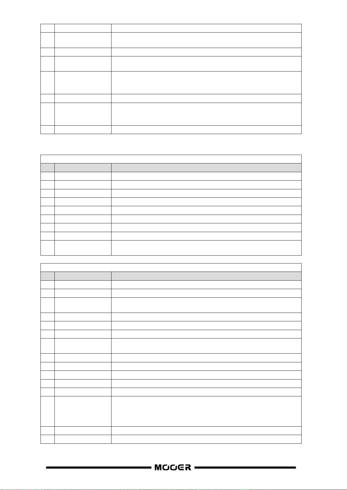
easier it is to trigger, and at approximately 0 dB it is turned off.
9
Filter
Choose the type of the filter envelopes. (LP: low pass / BP: band pass /
HP: high pass).
10
Rate
Adjusts the modulation rate of the delay repeats.
11
Range
Adjusts the modulation range of the delay repeats. Higher values result in
more obvious modulation effects.
12
Pan
Adjusts the sound panorama of the effect sound. L/R is for Left/Right,
Center is for Center, and the value indicates the percentage of the effect
focused on this side.
13
Level
Volume adjustment for the delay effect.
14
Tempo Sync
Switch to synchronize the effect with TAP TEMPO. When this parameter is
on, the delay time value changes to sub-divisions of the current BPM
tempo.
15
Trail
Switch to activate effect tails after switching - see Tails
REVERB modules
Effect Description
No.
Model name
Description
1
Room
Small room reverb
2
Hall
Concert hall reverb
3
Plate
Studio style plate reverb
4
Spring
Classic spring reverb tank
5
Mod
Reverb with modulation effect
6
Fl-Reverb
Reverb with flange effect
7
Reverse Reverb
Backwards Reverb
8
Swell Reverb
Brings in the reverb gradually behind the dry signal
9
Shimmer
Simulates reverberation with a distinctively sparkling high-frequency
range.
Parameter Description
No.
Model name
Description
1
Pre (Pre-Delay)
Delay time before the first reflections can be heard.
2
Decay
Length of the reverb trails.
3
Mix
Mix rate of the dry signal and wet signal. 0 is 100% dry sound. 100 is
100% reverb sound.
4
Low Cut
Low frequency EQ shelf
5
High Cut
High frequency EQ shelf
6
Quality
Choose between standard quality and high quality.
7
Spring Length
Simulated size of the springs in the spring tank. The length affects the
timbre of the spring reverb sound.
8
Spring Depth
Simulated strength of the springs in the spring tank.
9
Rate
Adjusts modulation speed. 100 is the fastest
10
Depth
Adjusts the modulation depth of the reverb trails.
11
Mod Level
Adjusts the modulation mix on the reverb trails.
12
Feedback
Adjusts the feedback intensity of the flanging reverb effect.
13
Mod-Delay
Adjusts the amount of delay in the flanging reverb effect. The larger the
value, the larger the delay, the lower the frequency of the effect's
feedback; the smaller the value, the smaller the delay, the higher the
frequency of the effect's feedback.
14
Attack
Rate of automatic volume swell of the reverb effect. 100 is the fastest.
15
Shimmer
Volume level of the shimmer effect.
54
 Loading...