


OWNER'S
MANUAL
© Copyright Marine
Projects
(Plymouth) Limited 1991
All rights
reserved,
including right of reproduction in whole or in
part,
in any form.
Issue 3
Page 1

Introduction
Moody yachts are manufactured by Marine Projects (Plymouth) Limited. High
quality raw materials are used throughout and all major components are
manufactured to strict tolerances to allow for easy replacement and repair during
the yacht's life. Strict quality control exists during the manufacture of all yachts. All
ancillary components such as hatches, winches, pumps, etc. are supplied by
manufacturers with a proven record of quality and reliability.
All specifications given in this handbook are given in good faith. Marine Projects
(Plymouth) Limited implement a policy of continual development and therefore
reserve the right to improve the specification without notice. The specifications
given in this handbook supersede any previously stated specifications.
Marine Projects (Plymouth) Limited, their agents, distributors or publishers cannot
be held responsible for any inaccuracies or
ommissions
in this handbook or for any
injuries to anyone, however caused, engaged in any activity involving a Moody yacht
or its ancillary equipment either on land or in the water.
This manual is intended to give the owner a better understanding of the
construction of a Moody yacht, the layout of its systems and how to service and
maintain it to best effect.
A well maintained yacht is ultimately more reliable and retains a higher resale value.
Safety
It is the duty of the skipper/owner of the yacht to ensure that the vessel and its crew
are fit to go to sea. Information concerning safety at sea can be obtained from the
Royal Yachting Association (RYA),
HM
Coastguards and the International
Maritime Organisation
(IMO),
who provide guidence and booklets on the subject.
Issue 3 Page 3

Contents
Details of ownership
Introduction
Safety
Contents
Hull, Deck gear & below decks
Hull___________________________________________Ll_
Keels____________________________________________1.1
Seacocks________________________________________1.2
Cathodic
protection___________________________________1.3
Hatches
and
portlights_________________________________1.3
Deck
gear__________________________________________1.6
Winches
and
windlasses__________________________________1.6
Below
decks_______________________________________1.7
Upholstery_______________________________________1.7
Maintenance 1.8
Hull
Seacocks
Sacrificial anodes
Antifouling
Upholstery
Ventilators
Deck plans
1.8
1.8
1.8
1.9
1.9
1.9
1.10
Moody
31____________________________________________1.10
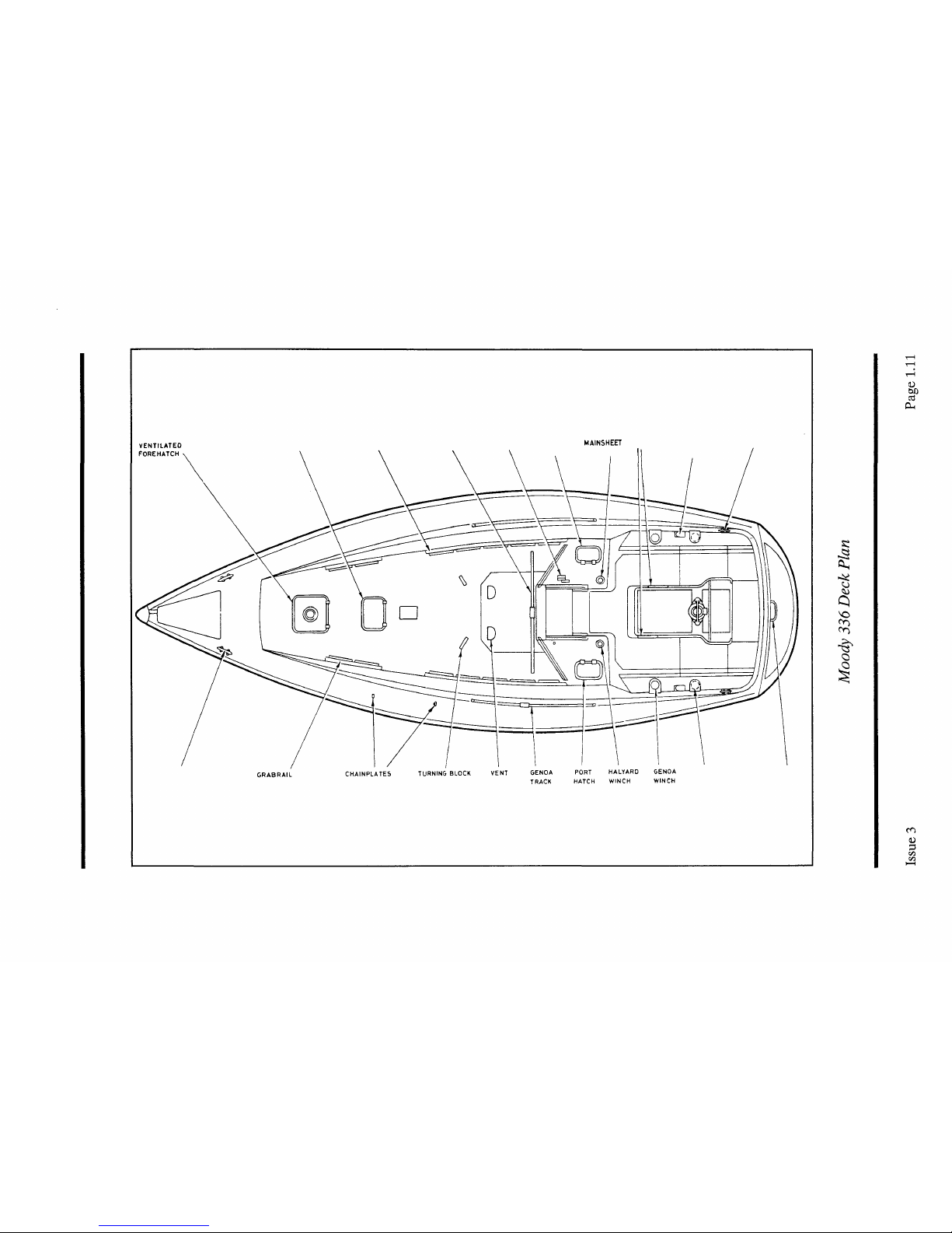
Moody
336___________________________________________1.11
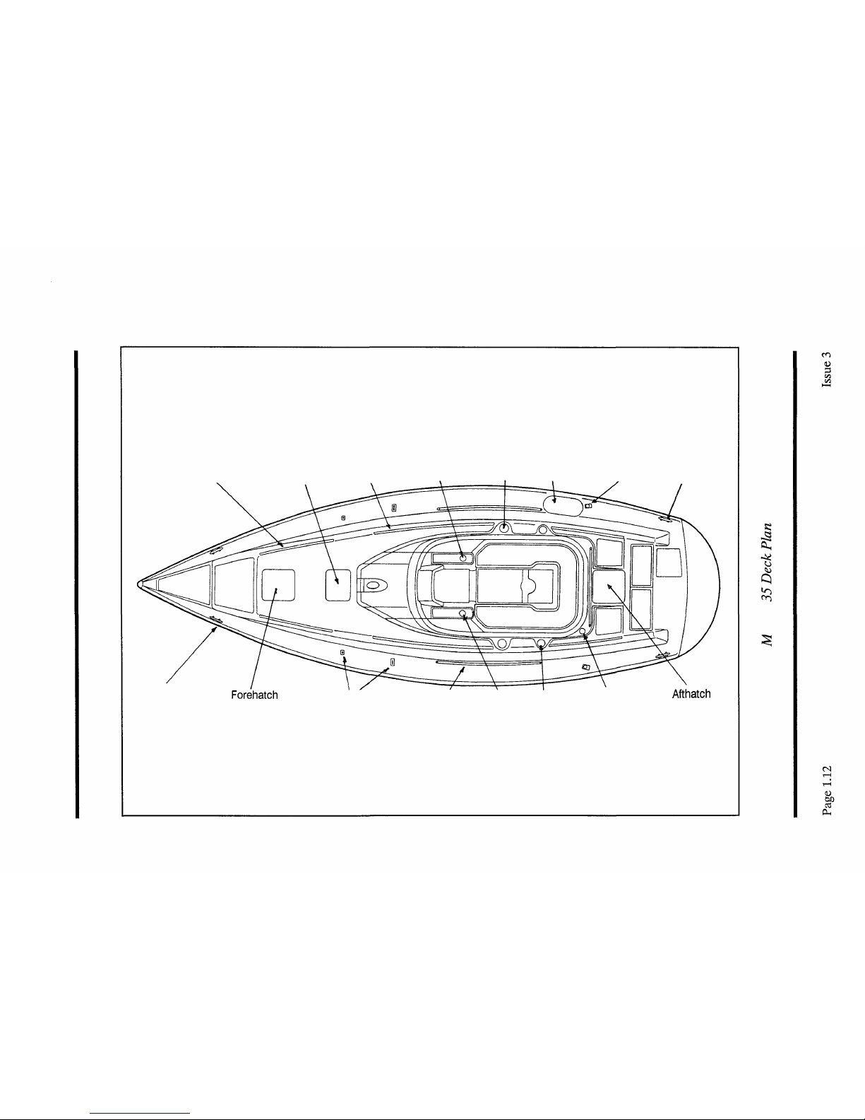
Moody
35_________________________________________1.12
Moody
376________________________________________1.13
Moody
425___________________________________________1.14
Eclipse
33____________________________________________1.15
Eclipse
38_________________________________________1.16
Eclipse
43_________________________________________1.17
Page 4 Issue 3

Sails,
spars & rigging
Spars
and
rig______________________________________2.1
Rigging_________________________________________2.1
Standing
rigging______________________________________2.1
Running
rigging______________________________________2.6
Sails______________________________________________2.6
Folding
sails________________________________________2.7
Setting
sails___________________________________2.9
Mainsail
reefing____________________________________
2.9
Maintenance________________________________________2.10
Rigging
checks______________________________________2.10
Mast____________________________________2.11
Roller
furling_____________________________________2.11
Sails____________________________________________2.11
Ropes_________________________________________________2.11
Steering systems
Single
station
steering
systems_____________________________________________3.1
Emergency
tiller_____________________________________3.1
Cobra
systems_______________________________________3.1
Constellation
systems___________________________________3.2
Dual
station
steering
systems_______________________________3.2
Inside
steering
station__________________________________3.2
Rudders_________________________________________3.3
Maintenance______________________________________3.4
Rudders__________________________________________3.4
Wheel steering systems__________________
3.4
Steering
system
installation
diagrams_______________________________________3.5
Cobra
5R
delux
steering
system_____________________________3.5
Cobra
5RISS
prestige
steering
system__________________________3.6
Constellation 400 steering system 3.7
Issue 3 Page 5

Engine systems
Engine
options________________________________________4.1
Running-in___________________________________________4.2
Fuel
systems__________________________________________4.3
Fuel
tank_________________________________________4.3
Fuel
stopcock_________________________________________4.3
Fuel
filter___________________________________________4.3
Water
trap________________________________________4.3
Return
pipes_______________________________________4.3
Fuel
contents_______________________________________4.3
Cooling
systems______________________________________4.4
Raw
water
cooled
engines________________________________4.4
Heat
exchanger
cooled
engines______________________________4.4
Water filter 4.5
Exhaust
systems_______________________________________4.5
Engine
controls________________________________________4.6
Gear
selection_________________________________________4.6
Engine
stop
mechanisms_________________________________4.6
Turbocharged
engines___________________________________4.7
Operating
instructions____________________________________4.7
Stern
gear__________________________________________4.8
Cutlass
bearing______________________________________4.8
Calcium
deposits_____________________________________4.9
Stern
glands________________________________________4.9
Bow thrusters________________________________________4.9
Maintenance________________________________________4.10
Basic
engine
care___________
4.10
Turbochargers______________________________________4.11
Engine
system
installation
diagrams___________________________4.12
Moody
31_________________________________________4.12
Moody
336___________________________________________4.13
Moody
35____________________________________________4.14
Moody
376___________________________________________4.15
Moody
425___________________________________________4.16
Eclipse
33___________________________________________4.17
Eclipse
38___________________________________________4.18
Eclipse 43 ___ 4.19
Page 6 Issue 3

Utilities
Electrical
systems____________________________________5.1
Batteries
- 12V
system__________________________________5.1
Shore
power - 240V
system________________________________5.2
Electrical
system
installation
diagrams__________________________5.4
Moody
31_________________________________________5.4
Moody
336___________________________________________5.5
Moody
35____________________________________________5.6
Moody
376___________________________________________5.7
Moody
425___________________________________________5.8
Eclipse
33___________________________________________5.9
Eclipse
38___________________________________________5.10
Eclipse
43____________________________________________5.11
Freshwater
systems_____________________________________5.14
Water
tanks________________________________________5.14
Pressure
pump_________________________________________5.14
Freshwater system installation
diagrams_________________________5.15
Moody
31____________________________________________5.15
Moody
336___________________________________________5.16
Moody
35____________________________________________5.17
Moody
376___________________________________________5.18
Moody
425___________________________________________5.19
Eclipse
33___________________________________________5.20
Eclipse
38___________________________________________5.21
Eclipse
43___________________________________________5.22
Waste
systems_______________________________________5.23
Shower
compartments__________________________________5.23
Marine
toilets_______________________________________5.23
Waste system installation
diagrams____________________________5.24
Moody 31
5.25
"
Moody
336___________________________________________5.26
Moody 35 5.27
Moody
376________________________________________5.28
Moody
425___________________________________________5.29
Eclipse
33___________________________________________5.30
Eclipse
38___________________________________________5.31
Eclipse
43
5.32
Issue 3 Page 7

Specifications
Moody
31_________________________________________8.1
Moody
336________________________________________8.1
Moody
35_________________________________________8.1
Moody
376________________________________________8.1
Moody
425___________________________________________8.1
Eclipse
33_________________________________________8.1
Eclipse
38_________________________________________8.1
Eclipse
43_________________________________________8.1
Issue 3 Page 9

Hull,
deck gear & below decks
Hull
Glass Reinforced Plastic (GRP) is used throughout the construction of the hull and
decks. Hull stiffening is achieved using balsa or foam
stiffeners
moulded to the
inside of the hull and by the fitting of bulkheads. Each bulkhead is bonded in
position using
GRP
and then further secured with bolts through the
GRP
bonding.
An inner GRP floor also adds to the strength and stability of the hull. Extra
strengthening is also applied to the keel attachment area in order to withstand the
loads imposed on the keel. Deck areas are surfaced with an integrally moulded non
slip finish.
Keels
The following keel options are
available:-
Yacht
Moody
31
Moody 336
Moody 35
Moody 376
Moody 425
Eclipse 33
Eclipse 38
Eclipse 43
Keel Options
Fin or Bilge
Fin or Bilge
Fin or Bilge
Fin or Scheel
Fin or Scheel
Fin or Bilge
Shoal
Shoal
Issue 3
Page 1.1

Seacocks________________________________________
Seacocks are fitted to all inlets and outlets which penetrate the hull below the
waterline. The hull area around the penetration point is reinforced with an internal
plywood backing plate which is resin coated and bedded on compound. With the
exception of the engine cooling system inlet, all current Moody yachts are fitted
with a ball valve combined with a skin fitting.
Water inlet seacock and strainer
This type of seacock is fitted to the engine
cooling system inlet and it is operated as
follows:
1 To open - turn the knob anticlockwise
2 To close - turn the knob clockwise
Skin
fittingi'seacock
This type of seacock is used for sink,
shower and cockpit drains and marine
toilet
inlet and outlets. It is operated as
follows:
1 To open - turn the lever to align with
the inlet/outlet hose.
2 To close - turn the lever until it is at
right angles to the inlet/outlet hose.
INLET HOSE
CONNECTION
SKIN FITTING
LEVER
(SHOWN IN
OPEN POSITION)
Water inlet seacock and strainer
LEVER
(SHOWN
IN OPEN
POSITION)
REINFORCED HOSE
SKIN
FITTING
JUBILEE
CLIP
PLYWOOD
BACKING PLATE
RESIN
COATING
Skin fittingi seacock
Page 1.2
Issue 3

Cathodic protection
All yachts are fitted with hull mounted sacrificial anodes as these give the best
results. These are usually mounted
in
the region of the engine compartment
to
keep
the bonding cable run to a minimum.
Attachment
This is achieved by using studs permanently fixed to the inside of the hull to which
the anode is secured using nuts and locking washers.
Bonding
Bonding cables are internally attached to the mounting studs. The anode is bonded
to the engine, stern tube, rudder stock and
T'
bracket. There is no requirement for
the more remote skin fittings and seacocks or the keel mounting bolts to be
protected.
Hatches
and
portlights________________________________
All yachts use the following range of
Lewmar
hatches and portlights;
Moody 31
Quantity
2
1
Type
Portlight
Hatch
Manufacturer
Vetus
Lewmar
Model No.
PT100
(White)
86005S
Size (")
123/8x51/2
19 3/4 X 19 3/4
Moody 336
Quantity
1
1
2
2
1
1
Type
Portlight
Portlight
Portlight
Hatch
Hatch
Hatch
Manufacturer
Lewmar
Lewmar
Lewmar
Lewmar
Lewmar
Lewmar
Model No.
8906
8912
8932
82005S
86005S
83005S
Size
(")
4x10
5x12
5x15
7 3/4 X 13
3/8
193/4X193/4
15
5/8
X 17 3/4
Issue 3
Page 1.3
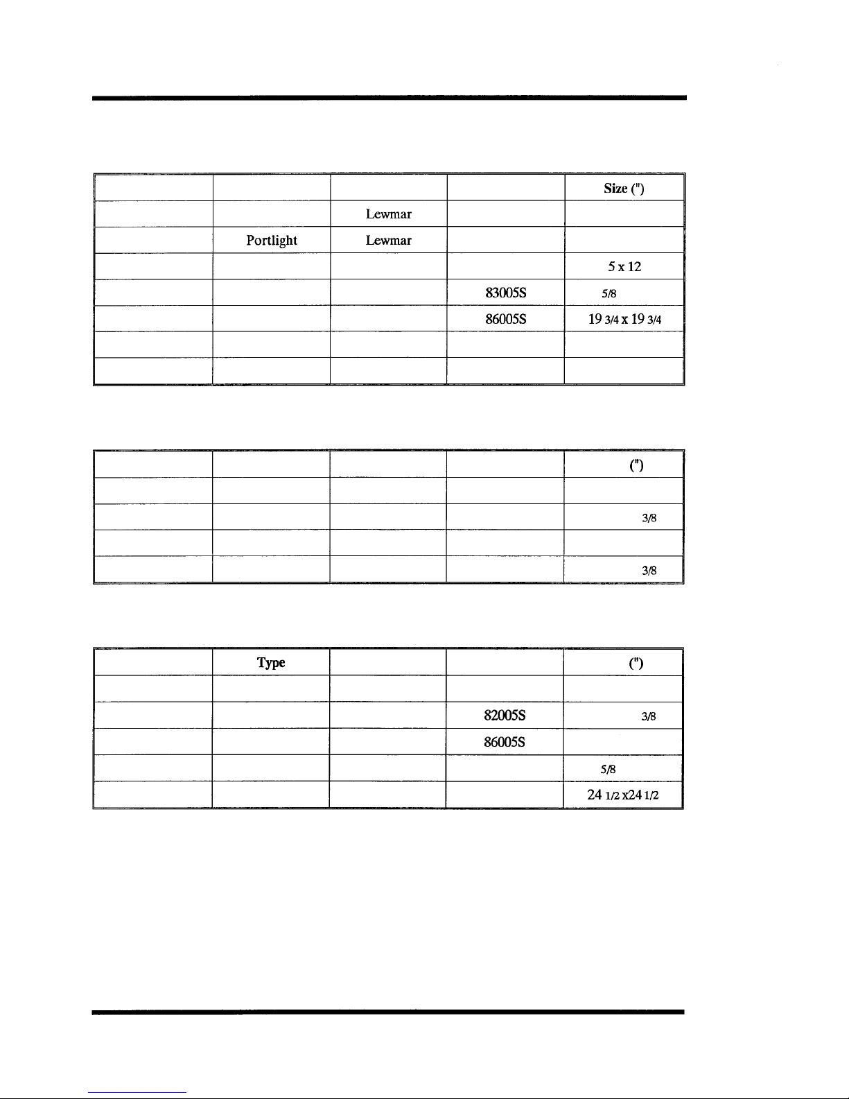
Moody 35
Quantity
1
2
1
1
2
2
2
Type
Portlight
Portlight
Portlight
Hatch
Hatch
Hatch Trim Kit
Hatch Trim Kit
Manufacturer
Lewmar
Lewmar
Lewmar
Lewmar
Lewmar
Lewmar
Lewmar
Model No.
8902
8941
8912
83005S
86005S
8776
8775
Size
(")
4x10
5x23
5x12
12
5/8
X 17 3/4
193/4x193/4
n/a
n/a
Moody 376
Quantity
2
1
2
1
Type
Portlight
Hatch
Hatch
Hatchh
Manufacturer
Lewmar
Lewmar
Lewmar
Lewmar
Model No.
8902
82005S
86005S
82005S
Size
(")
4x10
7 3/4 X 13
3/8
19 3/4 X 19 3/4
7 3/4 X 13
3/8
Moody 425
Quantity
4
1
1
2
1
Type
Portlight
Hatch
Hatch
Hatch
Hatch
Manufacturer
Lewmar
Lewmar
Lewmar
Lewmar
Lewmar
Model No.
8941
82005S
86005S
83005S
87005S
Size
(")
5x23
7 3/4 X 13
3/8
19 3/4 X 19 3/4
12
5/8
X 17 3/4
24
1/2x24
1/2
Page 1.4
Issue 3

Eclipse 33
Quantity
1
1
2
1
2
Type
Portlight
Portlight
Hatch
Hatch
Hatch
Manufacturer
Lewmar
Lewmar
Lewmar
Lewmar
Lewmar
Model No.
8902
8912
82005S
86005S
83005S
Size
(")
4x10
5x12
7 3/4 X 13
3/8
19 3/4 X 19 3/4
12
5/8
X 17 3/4
Eclipse 38
Quantity
2
3
1
1
1
Type
Hatch
Hatch
Hatch
Portlight
Portlight
Manufacturer
Lewmar
Lewmar
Lewmar
Lewmar
Lewmar
Model No.
83007S
82007S
86007S
8932
8912
Size (")
12
5/8
X 17 3/4
7 3/4 X 13
3/8
19 3/4 X 19 3/4
5x15
5x12
Eclipse 43
Quantity
1
1
4
1
2
Type
Portlight
Portlight
Hatch
Hatch
Hatch
Manufacturer
Lewmar
Lewmar
Lewmar
Lewmar
Lewmar
Model No.
8941
8912
82005S
87005S
85005S
Size
(")
5x23
5x12
7 3/4 X 13 3/8
24i/2x24l/2
14
5/8
x 19 3/4
f
Hull mounted port lights must be
kept
closed and secured when
underway.
Aluminium
* deadlights are supplied for hull mounted
portlights,
a plywood deadlight is supplied for all
transom windows.
Issue 3
Page 1.5

Deck gear
Winches and windlasses
The following
Lewmar
winches are used:
Yacht
Moody 31
Moody 336
Moody 35
Moody 376
Moody 425
Eclipse 33
Eclipse 38
Eclipse 43
Genoa
Sheets
L30c
L40c
L40
L43c
L52st
L40c
L46cst
L52cst
Main
Halyard
L8c
L8c
L8c
L16c
L30c
L7c
L16c
L30c
Genoa
Halyard
'as
main'
'as
main'
'as
main'
L16c
L40c
-
L16c
L40c
Genoa
Furling
Line
-
L8c*
L8c*
L8c
L8c
L6c
L16cst
L16cst
Furling
Mainsail
Controls
-
-
-
L16cst
L16c
L6c
L16cst
L30cst
Mainsheet
-
L8c
-
L8c
L16c
L6c
L16cst
L30cst
Mainsail
Reefing
Lines
L6c
L6c
L6c
-
-
-
L16cst
-
Furling genoa not fitted as standard.
Page 1.6
Issue 3

The following
windlasses
are offered as options:
Yacht
Moody 31
Moody 336
Moody 35
Moody 376
Moody 425
Eclipse 33
Eclipse 38
Eclipse 43
Option/model
-
*Royal
*Royal
*Seawolf520
Royal
*Seawolf520
Royal
*Seawolf520
Anchorman (gypsy only)
*Power 700
(gypsy only -12V)
Power 700
(gypsy only -12V)
Power 1000
(gypsy
only
-12V)
Manufacturer
-
Lofrans
Lofrans
Simpson Lawrence
Lofrans
Simpson Lawrence
Lofrans
Simpson Lawrence
Simpson Lawrence
Simpson Lawrence
Simpson Lawrence
Simpson Lawrence
Chain Size
-
8mm
8mm
5/16"
8mm
5/16"
10mm
9.5mm
5/16"
5/16"
9.5mm
9.5mm
* Not fitted as standard - 'Seawolf to be replaced March 1991.
Using the windlass
It is recommended that your anchor chain is suitably marked to indicate the
amount of chain you have out while at anchor.
When lying at anchor in a heavy swell the chain will snatch either causing chain slip
or excessive loads to be applied to the windlass. For safety it is recommended that
a rope bridle be applied to transfer the load to a cleat.
Below decks
Upholstery_______________________________________
Your yacht has been upholstered with either the Christiana, Ravenna, Dash or
Onyx range of materials. They all meet the Fire and Safety Regulation Act and
have been tested to BS5852
PTL
For information on care of your upholstery refer
to the maintenance section.
Issue 3
Page 1.7

Maintenance
Hull
Minor scratches and abrasions should be attended to in their early stages, initially
by using a medium grade rubbing compound. If this is ineffective, rub the area
lightly with 400 grade wet and dry paper (used with water) until the mark
disappears. Smooth the area with 800 grade followed by 1200 grade (both wet) and
then apply a silicone free wax polish.
Stress cracks should be looked at by an expert and some remedial action taken.
f Rubbing with abrasive compounds and materials removes the
gelcoat.
As this is only a thin
* layer, great care should be taken.
Annual cleaning
Wash the hull annually with warm water containing a little detergent. Stubborn
stains and polish should be removed with a recommended release agent or oil
removing fluid. Polish the hull with a silicone free wax polish.
Seacocks________________________________________
Check regularly:
1 Security of attachment
2 Security and condition of hose and hose clips
3 Free operation of the valve
Sacrificial
anodes____________________________________
The anode should be replaced when it is approximately two thirds eroded. If any
doubt exists as to whether the anode will survive the season - change it! The core
of the anode is a galvanised steel strip which provides the attachment lugs for the
anode. The anode is removed by undoing the two securing nuts and washers. It is
recommended that when replacing the anode, the nuts, washers and backing sheet
are also replaced.
Page 1.8 Issue 3

Antifouling______________________________________
Antifouling
should be checked on a regular basis and replaced at least once a
season.
The
antifouling
used
on
your
yacht
is
_____________________
Upholstery_________________________________________
Cleaning
Dust and grit should be removed frequently with a soft brush or the upholstery
attachment of a vacuum cleaner.
Creases
Where creases occur, raise the pile by brushing with a clean, damp cloth. Do not
saturate the fabric as the cotton backing may shrink. When dry, brush in the
direction of the pile with a soft brush.
Stains
Take immediate action, the longer stains are left the more difficult it is to remove
them. Nearly all stains can be removed by sponging lightly with warm water or a dry
foam upholstery shampoo. If this is not effective, covers can be removed and dry
cleaned. If heavily stained it is recommended that a reputable upholstery cleaner
is called in.
Ventilators______________________________________
Ensure that there is no entry of water through the deck seal. Reseal if necessary.
Issue 3 Page 1.9
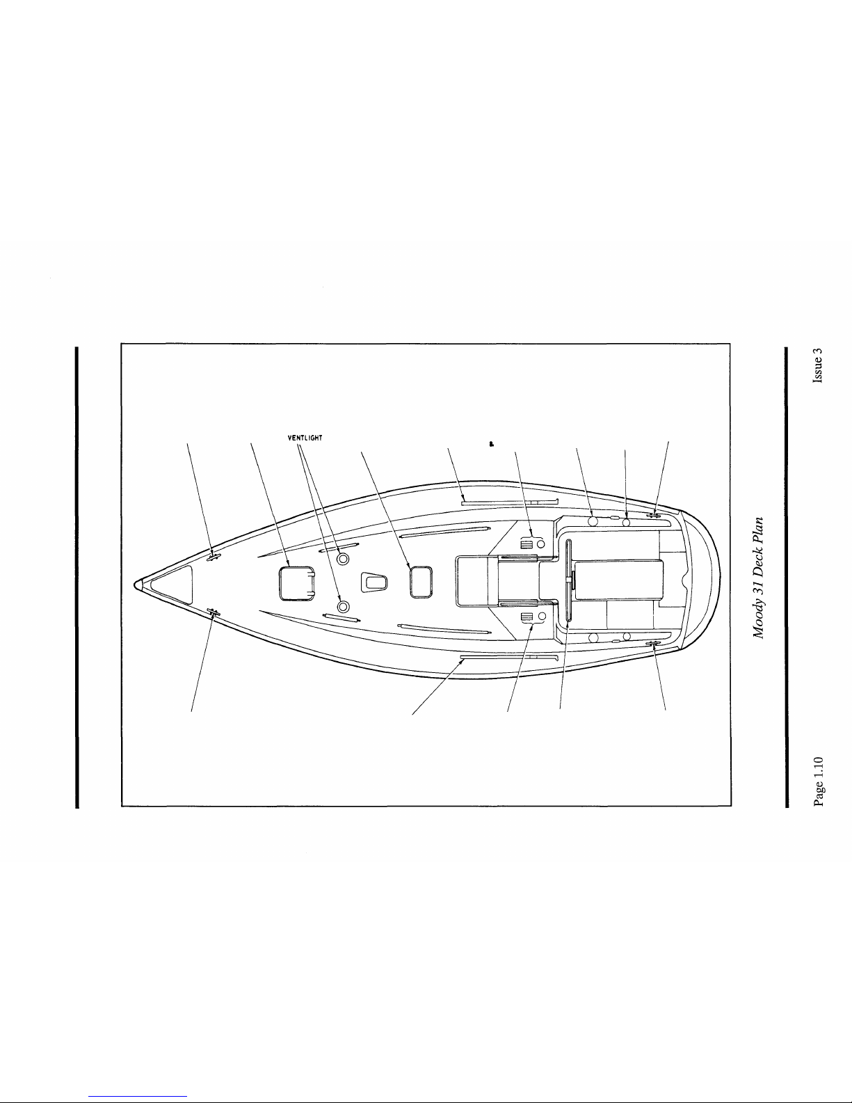
MOORING CLEAT FOREHATCH
VENTLIGHT
MOORING CLEAT
HATCH GENOA TRACK WINCH & CLUTCHES GENOA WINCH SPINNAKER WINCH MOORING CLEAT
(OPTIONAL) \ FOR MAIN I GENOA \ (OPTIONAL)
GENOA TRACK
SPINNAKER WINCH &
CLUTCHES (OPTIONAL)
MAIN SHEET TRACK
MOORING CLEAT
SALOON HATCH GRABRAIL
MAINSHEET TRACK JAMMER STARBOARD
MAINSHEET
PORT LIGHTS TURNING
HATCH \ WINCH |
||
BLOCK
MOORING CLEAT
MOORING CLEAT
SPINNAKER WINCH
(OPTIONAL)
D STEP
Grabrail
Saloon hatch Grabrail
Genoa Gas bottle Turning
winch locker block Mooring cleat
Mooring cleat
Forehatch
chain plates Genoa track Halyard Spinnaker Roller furling
winch winch winch
Afthatch
!
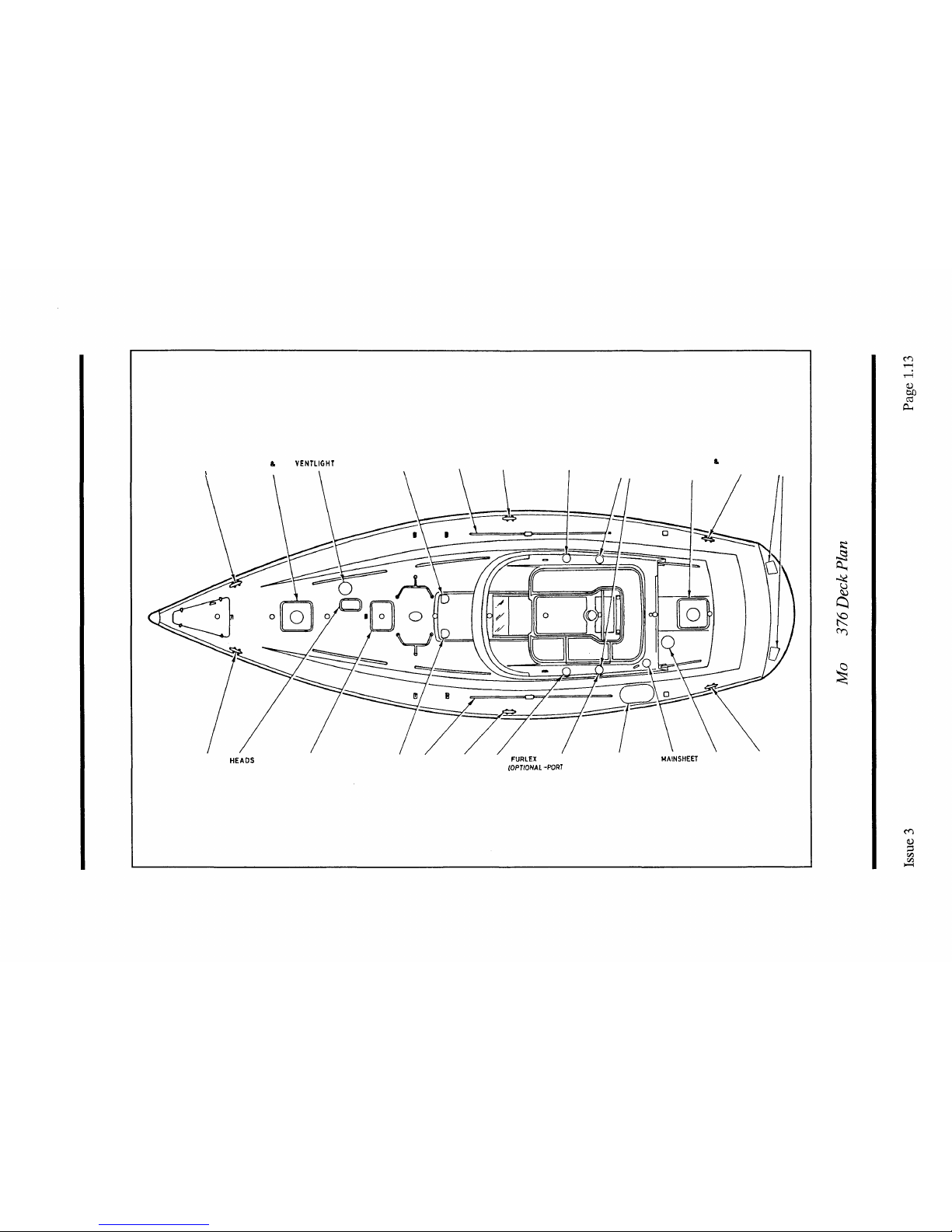
MOORING CLEAT FOREHATCH & VENTLIGHT
i
VENTILATOR
COWL VENT GENOA TRACK MOORING CLEAT GENOA WINCH SPINNAKER AFT HATCH
8.
MOORING PORT
WINCH VENTILATOR CLEAT LIGHTS
MOORING CLEAT
HEADS
HATCH SALOON HATCH COWL VENT GENOA MOORING GENOA
FURLEX
WINCH GAS BOTTLE
MAINSHEET
VENTLIGHT MOORING
TRACK CLEAT WINCH
(OPTIONAL-PORT
SIDE ONLY) LOCKER WINCH CLEAT
NOTE:
EMERGENCY TILLER ACCESS UNDER BUNK IN AFT CABIN
<S
t
co
CD
MOORING CLEAT
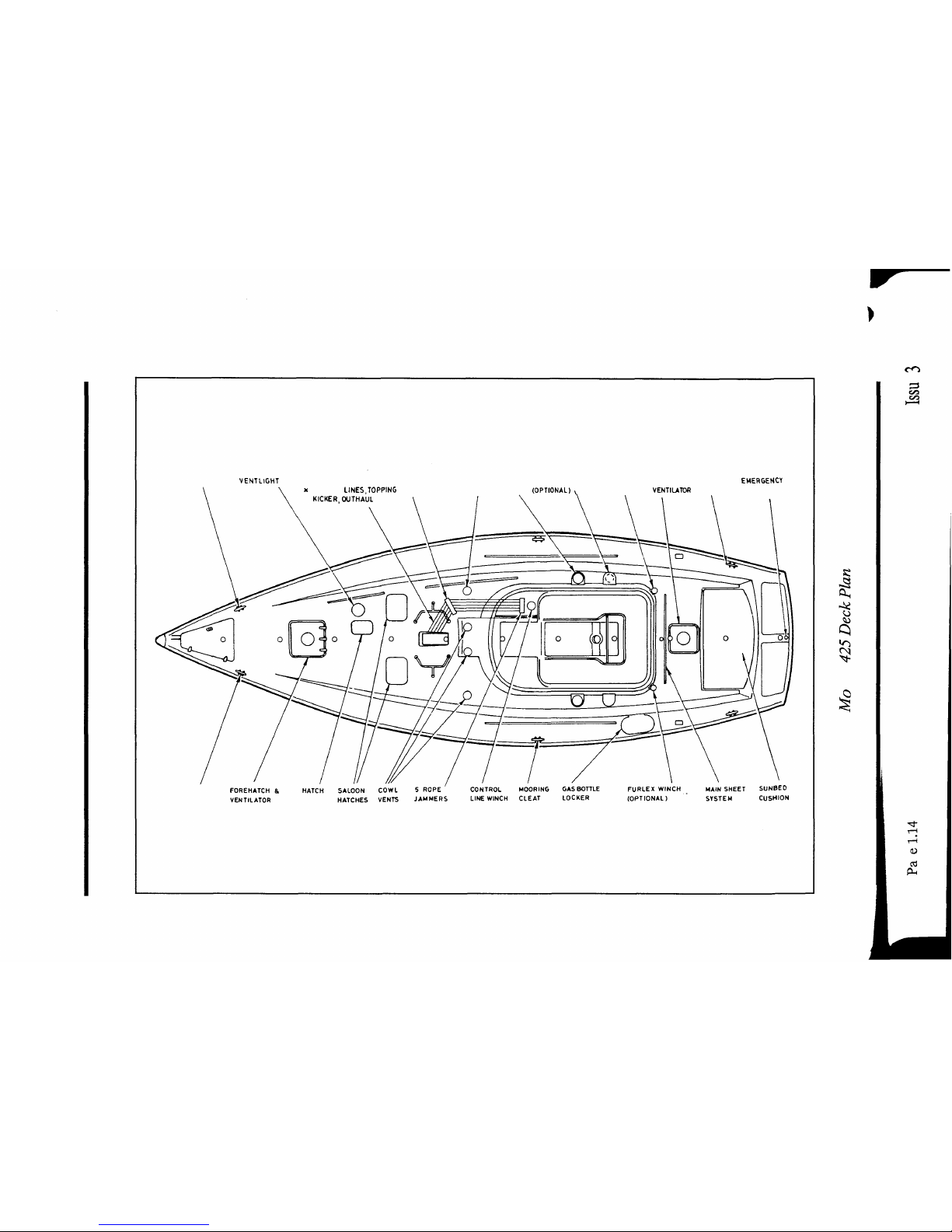
VENTLIGHT
5 LINES LEADING AFT 5 SHEAVE COWL GENOA SPINNAKER WINCH MAIN SHEET HATCH & MOORING
EMERGENCY
(2 i FURLING
LINES,TOPPING
DECK ORGANISER VENT WINCH
(OPTIONAL) v WINCH
VENTILATOR
CLEAT TILLER ACCESS
LIFT,
KICKER,
OUTHAUL
)
t
,O
MOORING CLEAT
DO
«J
PH
Eclipse 33 Deck Plan
Issue 3
Page 1.15

Hatch
Hatch Mainsheet track
Mainsheet
winch
Forehatch
Genoa
track Halyard winch Genoa Roller furling Turning
winch winch block
I
•fj*

Sails, spars & rigging
Spars
and
rig___________________________
Your yacht is fitted with a Kemp aluminium mast and boom which, given good
support, proper handling and caring routine mainenance, should be remarkably
durable. Information on stepping the mast
can
be gained from the Kemp handbook
supplied with the yacht.
Rigging______________________________
Standing
rigging_____________________________________
The standing rigging is the only support provided for the mast and it is vital that it
is adjusted and maintained correctly. In a seaway, if the rig is too slack, the mast
head or spreader area can build up movement thereby increasing the shock loading
on the stays. On the other hand, overtensioned rigging puts a higher total load on
the stays and can be just as damaging. The entire standing rigging is stainless steel
including all terminals, toggles, bottle screws and wire ropes. Some yachts are fitted
with a furling
headsail
system and an
in-mast
furling mainsail system. For further
information refer to
'Hints
and advice on rigging and tuning your Kemp
Mast',
supplied with the yacht.
Rigging adjustment
Stainless steel rigging stretches and should therefore be regularly checked and
adjusted, particularly during the first season. It is recommended that reference be
made to the instructions given in
'Hints
and advice on rigging and tuning your Kemp
Mast'
supplied with the yacht.
Issue 3 Page 2.1

Moody 31
STAY
FORESTAY
INNER
FORESTAY
CAP SHROUD
INTERMEDIATE
FORWARD
LOWER
AFT LOWER
BACKSTAY
BACKSTAY
SPAN
QTYPERSET
1
1
2
0
0
2
1
0
TOP END
FITTING
Eye swaged
Tee
Tee
Eye swaged, eye
talurit and tee
Eye swaged, eye
talurit and tee
Tee
Eye swaged
Eye swaged, eye
talurit and tee
BOTTOM END
FITTING
Fork
Rigging screw and
roller
Rigging screw and
roller
Rigging screw,
swageless and roller
Rigging screw,
swageless and roller
Rigging screw and
roller
Rigging screw
Rigging
scrw,
eye,
fork and swageless
OVERALL
LENGTH (M)
12.23
5.875
11.51
0
0
6.115
12.64
0
Moody 336
STAY
FORESTAY
INNER
FORESTAY
CAP SHROUD
INTERMEDIATE
FORWARD
LOWER
AFT LOWER
BACKSTAY
QTYPERSET
1
0
2
2
2
2
1
TOP END
FITTING
Eye swaged
-
Shroud
Shroud
Shroud
Shroud
Eye terminal
BOTTOM END
FITTING
Rigging screw
-
Rigging screw and
roller
Rigging screw and
roller
Rigging screw and
roller
Rigging screw and
roller
Rigging screw
OVERALL
LENGTH (M)
14.00
0
12.62
9.025
5.00
5.00
14.50
Page 2.2
Issue 3

Moody 35
STAY
FORESTAY
INNER
FORESTAY
CAP SHROUD
INTERMEDIATE
FORWARD
LOWER
AFT LOWER
BACKSTAY
QTYPERSET
1
0
2
2
2
2
1
TOP END
FITTING
Eye swaged
-
Shroud
Shroud
Shroud
Shroud
Eye swaged
BOTTOM END
FITTING
Rigging screw
-
Rigging screw and
roller
Rigging screw and
roller
Rigging screw and
roller
Rigging screw and
roller
Rigging screw and
roller
OVERALL
LENGTH (M)
13.275
0
12.6
9.01
5.095
5.0
14.105
Moody 376
STAY
FORESTAY
INNER
FORESTAY
CAP SHROUD
INTERMEDIATE
FORWARD
LOWER
AFT LOWER
BACKSTAY
QTYPERSET
0
1
2
2
0
2
1
TOP END
FITTING
-
Shroud
Shroud
Shroud
-
Shroud
Eye swaged
BOTTOM END
FITTING
-
Rigging screw and
roller
Rigging screw and
roller
Rigging screw
-
Rigging screw
Rigging screw
OVERALL
LENGTH (M)
0
4.58
14.07
9.52
0
4.9
15.445
Issue 3
Page 2.3

Moody 425
STAY
FORESTAY
INNER
FORESTAY
CAP SHROUD
INTERMEDIATE
FORWARD
LOWER
AFT LOWER
BACKSTAY
BACKSTAY SPAN
QTYPERSET
1
0
2
2
2
2
1
0
TOP END
FITTING
Eye swaged
Eye swaged, eye
talurit and tee
Tee
Tee
Eye swaged, eye
talurit and tee
Eye swaged, eye
talurit and tee
Eye swaged
Eye swaged, eye
talurit and tee
BOTTOM END
FITTING
Fork
Rigging
swrew,
eye,
swageless and roller
Rigging screw and
roller
Rigging screw and
roller
Rigging screw,
swageless and roller
Rigging screw,
swageless and roller
Rigging screw
Rigging screw, eye,
fork and swageless
OVERALL
LENGTH (M)
16.38
0
15.55
10.76
6.04
5.96
17.05
0
Eclipse 33
STAY
FORESTAY
INNER
FORESTAY
CAP SHROUD
INTERMEDIATE
FORWARD
LOWER
AFT LOWER
BACKSTAY
QTYPERSET
0
0
2
2
2
2
1
TOP END
FITTING
-
-
Shroud
Shroud
Shroud
Shroud
Eye swaged
BOTTOM END
FITTING
-
-
Rigging screw and
roller
Rigging screw and
roller
Rigging screw and
roller
Rigging screw and
roller
Rigging screw
OVERALL
LENGTH
0
0
11.913
8.304
4.418
4.241
13.375
Page 2.4
Issue 3

Eclipse 38
STAY
FORESTAY
INNER
FORESTAY
CAP SHROUD
INTERMEDIATE
FORWARD
LOWER
AFT LOWER
BACKSTAY
QTYPERSET
0
0
2
2
2
2
1
TOP END
FITTING
-
-
Shroud
Shroud
Shroud
Shroud
Eye swaged
BOTTOM END
FITTING
-
-
Rigging screw and
roller
Rigging screw and
roller
Rigging screw and
roller
Rigging screw and
roller
Rigging screw
OVERALL
LENGTH (M)
0
0
13.97
9.665
5.37
5.24
12.0
Eclipse 43
STAY
FORESTAY
INNER
FORESTAY
CAP SHROUD
INTERMEDIATE
FORWARD
LOWER
AFT LOWER
BACKSTAY
BACKSTAY SPAN
QTYPERSET
0
0
2
2
2
2
1
2
TOP END
FITTING
Eye swaged, eye
talurit and tee
Eye swaged, eye
talurit and tee
shroud terminal
Shroud terminal
Shroud terminal
Eye swaged, eye
talurit and shroud
terminal
Eye swaged
Eye swaged
BOTTOM END
FITTING
Rigging screw, eye
and swageless
Rigging screw, eye,
swageless and roller
Rigging screw and
roller
Rigging screw and
roller
Rigging screw and
roller
Rigging screw and
roller
Fork
Rigging screw
OVERALL
LENGTH
16.63
0
15.53
10.93
6.24
6.07
13.60
4.22
Issue 3
Page 2.5

Running rigging
The running rigging comprises all the lines and relative mechanics used to hoist and
control the sails, this includes halyards, sheets, guys, lifts, downhauls and outhauls
together with their various shackles, blocks, cleats and winches. It is essential that
they are inspected regularly for any signs of wear or stress. Information on types of
cordage, wire ropes and fittings can be gained from a good chandler.
Sails
All yachts are supplied with Lucas sails which are manufactured from woven
dacron. This material has good tensile strength, resists abrasion and is not unduly
affected by moisture, however, it can be damaged by ultra-violet light and should
not therefore be exposed unnecessarily to sunlight. If treated with care and
maintained correctly these sails should give many seasons good service.
Yacht
Moody 31
Moody 336
Moody 35
Moody 376
Moody 425
Eclipse 33
Eclipse 38
Eclipse 43
I(M)
11.73
12.88
12.88
14.33
15.77
12.19
14.33
16.00
J(M)
3.81
4.11
4.09
4.57
5.03
3.10
4.57
5.03
P(M)
10.21
10.97
10.90
12.60
13.95
10.51
12.50
14.02
E(M)
3.51
3.73
3.78
4.34
4.72
3.50
4.34
4.72
Page 2.6
Issue 3

Folding
Sails_____________________________________
Mainsail
If your yacht does not have a self-furling mainsail system, one of the easiest methods
of folding is with the sail still on the boom:
1 Tighten topping lift to support boom.
2 Lower the sail fully.
3 Ensure the coachroof hatches are closed.
4 Ease the tension in the foot of the sail by releasing the clew outhaul.
5 Remove the battens to minimise stretch and chafing in the batten pockets.
6 Stand close to the mast on the opposite side of the pile of mainsail.
7 With an assistant at the leech, take hold of the sail about eighteen inches from
the boom , pull up together and lay the sail halfway over the boom. The bottom
of the hanging fold should be just below the bottom of the boom.
8 Take a further foot of sail and fold back over the boom in the opposite direction.
9 Continue this layering action until the entire sail is laid over the boom.
1 o Secure the sail to the boom using sail ties.
11
The halyard can either be removed and stowed or left attached to the head of
the sail. If left on the sail, secure to the boom by passing a sail tie through the
head of the sail and then tension the halyard.
12
If the sail is to remain folded for more than a few hours, put the sail cover on to
prevent damage.
Issue 3 Page 2.7

Headsails
Some yachts are fitted with furling headsails but if not, the headsail must be
removed and bagged when not in use.
Bagging
1 Put the head of the sail into the sailbag.
2 Work the luff, leech and body of the sail in together.
3 Leave the tack and clew until last and pass the sailbag neck cord through both
tack and clew before drawing tight. This enables the tack to be connected to the
stemhead and the sheets to be fitted to the clew before the sail is released from
the sailbag. The sheets can then be run back and secured without being snatched
by the sail. The sail can also be hanked to the forestay, one hank at a time, until
only the head is left to be attached to the halyard. In adverse conditions sails
bagged in this way can save a great deal of time on the foredeck.
Folding
1 Lay the headsail out flat in a convenient position, a pontoon or jetty is ideal.
2 The sail should then be folded following the steps illustrated.
Folding a headsail
Page 2.8
Issue 3

Setting
sails______________________________________
No yacht
wil
sail well if the sails are badly set. The points which follow are therefore
included to assist in setting sails correctly.
Hoisting
Whilst this is a very straight forward procedure in itself, the amount of tension in
the halyard depends on wind conditions. All modern sails respond well to differing
tensions. Hoist the sail fully ensuring that on a mainsail there are no wrinkles in the
luff and also that on a
headsail
the luff does not curve away from the forestay
between the hanks. Creases in a sail are the first sign of incorrect tension and
depending on their position on the sail, indicate whether there is too much or too
little tension in the halyard.
Sheeting and trimming
The basic rule of sail sheeting is "let it out till it flaps,
pul
it in till it stops."
Trimming and sheeting are best explained in books specifically written for the
purpose. It is recommended that every yacht's library has one.
Kicker
This controls the amount of twist in the mainsail and also ensures that the boom
does not
'kick
up'.
Therefore, there must always be some tension in the kicking
strap, the only exception being when the mainsail is sheeted in hard. The easiest
way to tension the kicking strap to the optimum position is by using the top batten
as a guide. This should be parallel to the boom. If it lies to leeward, tighten the
kicking strap and if it lies to windward loosen it.
Mainsail
reefing_____________________________________
All current production yachts are fitted with either slab reefing or in-mast furling
systems.
Issue 3 Page 2.9

Maintenance
Rigging checks
During the sailing season when your yacht is in commission, regular maintenance
checks should be carried out and particularly before a long voyage.
1 Examine all steel/wire ropes for corrosion, wear and damage.
2 Examine all terminations for signs of wear, cracks or damage. Pay particular
attention to all split pins, they should be the largest size possible to pass through
the cotter pinhole with at least 3/4" protruding through the hole.
3 Examine all bottle screws for signs of wear or damage and ensure they are
'in
safety',
i.e. the inner threads are visible through both safety holes. Where bottle
screws are covered with tape or plastic tubing, remove to enable examination.
4 Ensure the ends of the spreader bar are protected to prevent sail
chafing.Ensure
the rig is correctly adjusted.
5 Remove halyards from the mast leaving messenger lines for
rereefing.
6 Check all running rigging for signs of wear, paying particular attention to all eye
splices and end terminations. On the wire/rope halyards check the wire rope
splice. If the rope side of the splice is starting to swell then the wire has started
to rust and the halyard should be replaced. Wash halyards which are not being
replaced and soak rope joins in linseed oil (also soak joins on new halyards).
7 Check over the standing rigging paying particular attention to the wire where it
enters the swage fittings. Should there
be
any sign at all of cracking in any one
of the wire strands then replace the shroud concerned.
8 Look for signs of wear of ridging on clevis pins where they may rock or work in
chain plates or shroud tangs, also
look
for corresponding wear on mating fittings.
9 Where shrouds locate into mast by means of a shroud terminal in a slot, ensure
that there is no undue wear.
10
Renew all split pins for recommissioning.
Page
2.10
IssueS

Mast____________________________________________
See autumn overhaul in Kemps
'Hints
and advice on rigging and tuning your Kemp
mast'
booklet.
Roller
furling_______________________________________
Roller furling gear must be lubricated and cleaned regularly in accordance with the
manufacturers
recommendations..
Sails__________________________________________
Sails should be checked regularly and repairs effected for the following:
1 Chaffing occurring mainly at spreaders and on foot of large sails.
2 Tears at batten pockets and at all attachment points, tack, clew, head, sail and
reefing cringles.
3 Any other damage.
4 When a sail is lowered it should be bagged and stowed below as soon as possible.
5 On return to harbour, release the tension on the clew
outhaul
of the main,
remove batterns, flake the sail over the boom, secure with ties and put on sail
cover.
6 Furling headsails and mainsails should be checked carefully for any signs of wear
on the stitched seams.
Ropes___________________________________________
All ropes should be checked regularly during the season for the following:
1 Signs of wear or damage where constantly cleated, clamped or passed round
sheave blocks or through fairleads.
2 Damage to whipping or heat shrink sleeves.
3 All splices are serviceable. It is important where polyester ropes are spliced to
steel wire ropes, such as halyards.
Issue 3 Page 2.11

Steering systems
Single station steering systems
All steering systems fitted are manufactured by
Whitlock
Marine
Yacht
*Moody 31
Moody 336
Moody 35
Moody 376
Moody 425
Model
Cobra 5R
Delux
Cobra 5R Delux
Constellation 400
Constellation 400
Constellation 400
Wheel Size
26"
30"
36"
36"
36"
* Tiller steering is standard on Moody
31,
wheel steering fitted only as an option.
Emergency
tiller___________________________________
All yachts, less those fitted with two steering positions as standard, are supplied
with an emergency tiller. This is fitted in a tiller socket located either within the
yacht or externally under a blanking cover.
Cobra
systems_____________________________________
The system is complete with friction brake and integral stainless steel output lever.
The system consists of:
Universal tiller lever, bored and keyed to suit the rudder stock.
Stainless steel draglink complete with rose joints and rudder stop ring, fitted
beneath the pedestal.
Either Retrofit guard rail or a single lever engine control and guard rail (see
illustrations on pages 3.5 and 3.6.
Issue 3
Page 3.1

Constellation Systems
The
Whitlock
Constellation 400 system, comprises a pedestal complete with friction
brake and conduit plate assembly.
The system consists of:
Engine control and guard rail.
2-turn tangential Unit.
12" or 15" quadrant in either aluminium or bronze, bored and keyed to suit rudder
stock.
2 or 3 conduits with fittings and 6 mm or 8 mm stainless steel wire.
On some yachts, a 6" double conduit to sheave adaptor.
2 or 3 turn, 5/8" pitch, stainless steel chain assembly (see illustration on page 3.7).
Dual station steering systems
Yacht
Eclipse 33
Eclipse 38
Eclipse 43
Model
Cobra 5R
Delux
Cobra 5R Delux
Cobra
5R
ISS
Prestige
Wheel Size (Cockpit)
36"
40"
40"
Wheel Size (Inside)
18"
20"
20"
Inside Steering Station
Where used, the inside steering is a 2-turn bulkhead unit with integral
2:1
multiplier
which results in 4 turns of the wheel lock to lock. The system consists
of:
2 conduits with fittings and 5mm stainless steel wire.
12" quadrant, bored and keyed to suit rudder stock.
2-turn tangential unit.
Clutched helm, it is recommended for reasons of safety that the inner helm be
disengaged using the clutch when the cockpit steering station is in use.
Page 3.2
Issue 3

Rudders______________________________
All yachts are fitted with a partial skeg hung, semi-balanced rudder. It consists of
a long stainless steel stock passing through the hull. A stainless steel stiffening plate
is welded to the stock and a
GRP
rudder is moulded over the stock and plate. For
wheel operation, a steering quadrant is fitted to the stock within the hull area. All
craft use 'O' rings in polyacetal tubes which are fitted inside GRP tubes.
Polyacetal
bearing
Neoprene
'O'
ring seals
Stainless steel set screw
CSM around tube
CSM over plywood
Neoprene
'O'
ring seal
Seal around bottom of
tube
(epoxy
or similar)
FORWARD
Rudder Tube Assembly
Issue 3
Page 3.3

Maintenance
Rudders
Rudders become less efficient as bush wear increases. Bushes should therefore be
checked at the end of each season and repaired as necessary. Rudders may leak
slightly as the 'O' rings become worn. These should be checked at the end of each
season and replaced as necessary.
Wheel
Steering
Systems_______________________________
Whitlock Cobra and Constellation steering systems are extremely robust, reliable
and relatively maintenance free. In order for the system to maintain its
performance, the following is recommended.
1 Periodically wash the paint finish of the pedestal with fresh water. Wax with
conventional car polish.
2 Check that water is not gaining entry to the inside of the pedestal assembly. A
drain hole is proveded in the lower housing to allow for draining of any
condensation. If large quantities of water are evident it will be necessary to
remove the top cover and reseal using a proprietary sealant. Take care to remove
all old sealant from the pedestal head and top cover before attempting to apply
new sealant.
Idf
a compass is fitted check that it is also properly sealed.
3 At lewast twice a season regrease the lower bearing via the grease nipple
Valvolene XL and Vickers Neox greases are recommended.
4 Inspect Cobra systems for security of tiller arm and draglink annually. Ensure
draglink joints rotate freely.
Constellation systems only
1 Inspect conduits and wire assemblies for wear and damage annually.
2 Periodically check the tension in the wires. To adjust, proceed as follow:
Slacken the lock nut and retaining nut. Pull the cable tight by hand and tighten
the retaining nut as far as possible by hand. Tighten the lock nut to
30ft/lbs
using
a torque wrench. Check steering for backlash. DO NOT
OVERTIGHTEN
as
this will cause excessive wear on the cables, heavy steering and loss of
'feel'.
3 At least twice a season and before an major voyage, check the security of
quadrant mounting bolts. Lubricate eyebolts and sheave bush with Silicone
based grease.
The stainless steel wire
used
has a finite life. It is recommended that it is renewed
after every fifth season.
Page 3.4 Issue 3

1 Steering wheel
2 Pedestal assembly
3 Output lever integral with pedestal
4 Draglink assembly with rosejoints
5 Tiller arm
Cobra 5R
Delwc
Steering System
Issue 3
Page 3.5

Cobra
5RISS
Prestige Steering System
Page 3.6
Issue 3

1 Steering wheel
2 Pedestal assembly
3 Output lever integral with pedestal
4 Draglink assembly with rosejoints
5 Tiller arm
Cobra 5R
Delwc
Steering System
Issue 3
Page 3.5

Cobra
5RISS
Prestige Steering System
Page 3.6
Issue 3

Constellation 400 Steering System
Issue 3
Page 3.7

Engine systems
Engine Options
The Engines fitted to the current production yachts are all four stroke engines:
Yacht
Moody 31
Moody 336
Moody 35
Moody 376
Moody 425
Eclipse 33
Eclipse 38
Eclipse 43
Standard Engine
Volvo 2003
28hp
Volvo 2003
28hp
Thornycroft
T80
35hp
Thornycroft
T80
35hp
Thornycroft
T110
55hp
Volvo 2003
28hp
Perkins
PrimaM60
Perkins
Prima
M80T
78hp
Gear Box
Volvo MS2
Volvo MS2
Hurth
HWB100
Hurth
HWB100
Hurth
HWB100
Volvo MS2
Hurth
HWB250
Hurth
HWB250
Tank
Capacity
Litres
91
202
186
204
273
182
273
409
Prop Sizes
16xl4x2LH
Aquasail
15xl4.5x2RH fixed
Clements
16x11x2 Aquasail
16xllx2RH Aquasail
17xllx2RH
fixed
Aquasail or 17xlOx3RH
fixed aquapoise
18xllx2LH
Aquasail or
17xl2x2LH
Aquasail
17xllx3RH
Clements
18xl3x3RH
Aquasail
It is possible to fit
turbocharged
systems if required.
Each yacht has an engine maintenance manual supplied by the manufacturer.
Issue 3
Page 4.1

Running
-In______________________________________
It is recommended to run-in new engines (20 hours) following these basic points:
1 Do not excessively rev engine.
2 In the event of a warning light or alarm, stop the engine immediately.
3 All gear changes should be implemented at low engine revolution (i.e. from
neutral).
4 Place gear selection control in reverse position or for fixed bladed props, to
reduce drag, prop can be left in neutral whilst under sail. Never put the gear
lever in the position corresponding to the yacht's direction of travel.
5 Run the engine occasionally during long voyages to keep batteries charged.
6 Do not switch off the ignition and battery switch until engine has fully stopped.
7 Ensure that servicing is carried out by an official service agent.
8 Check engine anode (see cathodic protection).
The cooling system is filled with liquid and should be drained when there is risk of
frost and during
winterisation.
In certain cases a suction action may occur when the
sea water system is being drained. Close all drainage points when the boat is not
under constant supervision. Incorrect drainage can cause the yacht to fill with water
and sink.
Your engine has been installed in precise alignment with the shaft. However, with
flexibly mounted engines it is possible for misalignment to occur, it is good practise
to have it checked when the engine is being serviced.
Care should be taken not to soil the rubber mounts with diesel or lubricants as this
will cause deterioration of the rubber.
Page 4.2 Issue 3

Fuel
systems_____________________________
Fuel
tank_________________________________________
The fuel tanks for all yachts are constructed from heavy gauge mild steel, externally
treated with a corrosion resistant paint finish. Where tanks are exposed to damage
by stowed equipment, a regular check should be made to ensure there is no damage
to the external finish causing rust spots to develop. To prevent condensation
forming inside the tank, keep the fuel tank full whenever possible.
Fuel
stopcock____________________________________
All yachts have a stopcock fitted in the fuel feed line. Unless the fuel system is
undergoing repairs or maintenance, it is normal to leave the stopcock on. If the
engine is run with the stopcock turned
off,
an airlock may occur which will making
it necessary to bleed the system.
FuelfiUer_________________________________________
A fuel filter is mounted on a bulkhead within the engine compartment.
Water
trap_________________________________________
r
A diesel water tap is mounted on a bulkhead within the engine compartment. The
bowl should be
checked
periodically for water content and drained as necessary.
Return
pipes______________________________________
All diesel engine installations in Moody yachts are fitted with fuel return pipes to
allow surplus fuel to be returned to the tank.
Fuel
contents_____________________________________
Fuel tank contents are determined by either sightglass or fuel gauge.
Issue 3 Page 4.3

Cooling systems
The basic cooling system is illustrated below. Seawater is drawn into the system by
the engine impeller, entering the yacht through a skin fitting. It passes through a
seacock and a filter before passing through the engine and the mixer box and out
through the exhaust system. Its passage through the engine depends on the type of
cooling system.
Raw
water
cooled
engines______________________________
In this type of engine the raw seawater circulates through galleries in the engine
and gearbox before being injected into the exhaust pipe for discharge.
Heat
exchanger
cooled
engines____________________________
This type of system uses fresh water which circulates through the engine and a heat
exchanger in a closed circuit. Raw seawater passes through the heat exchanger
where the heat is transferred from the closed circuit freshwater system. The heated
seawater is then injected into the exhaust system for discharge. This type of engine
runs at a slightly higher temperature than the raw water type.
Water in
Water out
'Swan
neck'
Water and
exhaust out
Water inlet valve
and strainer
Stainless steel
mixer box
Stainless steel
skin fitting
Basic Engine Cooling and Exhaust System
Page 4.4
Issue 3

WaterfiUer______________________________________
This is a very basic strainer forming part of the water inlet seacock (see illustration
on page 1.2). Inspection and cleaning should be carried out as follows:
1 Ensure the seacock is in the closed position.
2 Unscrew the wing nuts and swing the cap aside.
3 Withdraw the plastic filter and
inspect/clean.
4 Reassemble, ensuring the cap is clamped tightly to prevent leakage.
If air is drawn into the system through this filter, the engine may overheat
causing damage.
5 Turn on the seacock and check for leaks.
Exhaust
systems_________________________
The injection of the exhaust gasses into the cooling water in the mixer box reduces
the temperature of the exhaust gasses allowing them to be discharged through
reinforced rubber tubing and a stainless steel
skin
fitting. The exhaust tube has a
'swan
neck'
to reduce the possibility of seawater being forced into the exhaust and
into the cylinders, causing damage to the engine. This problem can further be
avoided if the following action is taken:
After three or four attempts to start a stubborn engine, turn off the water inlet
seacock until the engine starts.
When starting the engine check that water is being ejected through the exhaust
within 20 seconds. If not, switch off and investigate. First check that the water inlet
seacock is open.
Issue 3 Page 4.5

Engine controls
All yachts are fitted with the a single lever
'TX'
type throttle and gear change lever.
N=Neutral
F=Forward
Gear
R=Reverse
Gear
T=Throttle
Increase
Gear selection
Forward is selected by pushing the lever
forward, the further forward it is pushing the
higher the engine revs.
Reverse is selected by pulling lever aft and
again, the further aft it is pulled, the higher
the engine revs.
To increase engine revs without selecting a
gear, press and hold the gear disengage
button (1) then move lever to
forward/reverse. Disengage button (1) will
pop out when passing lever through neutral.
/
Warning: Gear selection will re-engage
when lever is returned to neutral
Lever
Disengage button
TX Lever
Engine stop mechanisms
Diesel engines are stopped by preventing the fuel being injected into the cylinders.
This is achieved using a cable operated control marked
'STOP'
To stop, pull and
hold the control knob until the engine has stopped. When the engine has stopped,
push the control knob back to the
'RUN'
position. Then switch off the engine
ignition.
This control also operates a cold start, by pulling out once before trying to start
engine.
/
If it is not pushed all the way in, the engine will not start.
f
On engines fitted with mechanical stop
systems,
do not turn the key to the
'off-position
whilst
* the engine is running. This can seriously damage the charging
system,
particularly the
alternator.
Page 4.6
Issue 3

/
If your engine fails to start,
when
the batteries are in good condition, check
first that the engine
'stop'
control is in the
'run'position.
On engines fitted with mechanical stop systems, do not turn the key to the
'off
position whilst the engine is running. This can seriously damage the charging
system, particularly the alternator.
If your engine fails to start, when the batteries are in good condition, check first
that the engine
'STOP'
control is in the
'Run'
position.
Eclipse 38 and 43 engine stop mechanisms
For yachts fitted with
thorneycroft
engines:
1 Ensure gear lever is in neutral and engine revs are idling.
2 Press and hold the engine STOP button until audible alarm sounds.
3 Turn ignition switch (key) to the OFF position.
Turbocharged
engines
(optional)________________
The turbocharger is used primarily to attain higher power output with better fuel
economy.
Turbocharging
is a form of supercharging which uses exhaust gases to
drive a compressor to force more air into the
cylinders.
This means that more fuel
can be injected into the cylinders and thus produce more power.
Operating
instructions
(turbocharged
engines)____________________
The same operating procedure applies as for the basic engine but attention should
be paid to the following points:
1 Do not run at idling speed for too long. The temperature in the combustion
chamber becomes too low for effective combustion and the engine produces
very unpleasant black exhaust fumes.
2 Do not attempt to charge batteries at idling speed as most generators and
alternators only charge above 1500 rpm.
3 Volvo 2003T engines should be run at 2,500 rpm or more for
25%
of the engine
running time to avoid low temperature glazing of the cylinder bores.
Issue 3 Page 4.7

4 If the engine has been run hard for a long period, let it idle for a few minutes
before switching off. This is sometimes known as
'Turbo
Run
Down'.
In all
engines, it will avoid the
risk
of
'After
Boil',
a condition where the cooling system
temperature continues to rise because of lack of circulation. Overheating can
cause excessive bearing wear in the
turbocharger.
Stern
gear_____________________________
All yachts are fitted with a 'P' bracket type stern bearing. The strut is either pinned
through iroko hardwood blocks secured to the hull and glassed over, or bolted to a
reinforced
area to the hull. One securing bolt is electrically bonded to the sacrificial
anode for
cathodic
protection. A water lubricated
'Cutlass'
bearing supports the
stainless steel propeller shaft. The propeller shaft passes through a GRP stern tube
which is bonded to the hull. The tube is offset to enable the shaft to be withdrawn
without obstruction from the rudder.
Bronze fitting holding
gland packing Jubilee clips Backing plate Bolts
Gland packing /
CSM around tube
Rubboseal
Stainless steel shaft Reinforced rubber seal
housing gland bearing
and stern tude connections
GRP tube, gel coat seal
inside and out
'P'
Bracket with
Cutlass bearing
Typical stem gear installation
Cutlass bearing
All yachts use either 1" or
li/4"
cutlass bearings in the
'P'
bracket.
This type of water lubricated bearing is normally manufactured from neoprene or
polyurethane
and has a long life in clean water. High silt, sand and mud levels will
cause accelerated wear.
Page 4.8
Issue 3

Calcium deposits
Where yachts remain unused for long periods it is possible for a hard calcium
deposit to form on the propeller shaft.
If
this deposit forms between the joins in the
cutlass bearing, when the shaft revolves for the first tune the hard calcium deposit
can cause damage to the bearing surface. This is normally associated with noise and
vibration from the bearing area. If this happens stop the engine immediately and
investigate. The deposit can be removed with a sharp scraper. To gain access to the
bearing area, uncouple the propeller shaft at the engine and slide it back until the
affected area is exposed.
Stern
glands_____________________________________
The stern glands on all yachts have
PTFE
packing. This type of gland is water
lubricated, but the locking nut should be given a partial turn daily prior to motoring
to prevent the ingress of water.
Bow thrusters___________________________
The Eclipse 43 and 38 have a three bladed propeller sited inside a transverse tube
near the bow. The symmetrical design produces equal thrust whichever way it
rotates and allows for precise
manoevring.
/
It is advisable to keep operation of the bow
thruster
to a minimum as it uses
a high level of battery power.
Issue 3 Page 4.9

Maintenance
Basic engine care
The following basic points, if adhered to, will ensure long engine life. The most
critical period in the life of a marine
diesel
engine is the first 20 - 30 running hours.
If in any doubt, the engine manufacturer's manual should be referred to.
1 Do not start an engine unless you are sure:
• Engine oil level is satisfactory.
• Gearbox oil level is satisfactory.
• Coolant level is satisfactory (Heat exchanger cooled engines only).
• Throttle set correctly - OUT OF GEAR.
• Fuel stopcock turned on.
• Fuel is free from contamination.
• Water inlet seacock is turned on.
2 Immediately after starting, check:
• Oil pressure warning light extinguished.
• Charging light extinguished (or ammeter reading satisfactory).
• Water emission from exhaust.
3 Avoid high revs.
4 Allow engine revs to decrease to idle before changing gear.
5 Do not allow engine to run at a low idle for long periods (associated with the
production of black noxious fumes).
6 During running, check any instrumentation, ie, water temperature gauge, oil
pressure warning light, etc.
7 Prior to stopping engine allow to idle for a few minutes with the gear lever in
neutral.
8 After stopping engine return
'STOP'
control to the
'Run'
position.
Page 4.10 Issue 3

9 Ensure the first service is carried out by a manufacturer recommended agent.
10
Ensure all subsequent services are carried out at the correct frequency.
11
Ensure ONLY the correct lubricants are used.
12 Adhere to all manufacturer's recommendations.
13
Keep an engine log.
Turbochargers____________________________________
Correct lubrication is critical for turbocharged engines using the correct grade at
the recommended frequency.
For further information see section on
dewinterising.
Issue 3
Page
4.11

Moody 31 Engine System Installation
Page 4.12
Issue 3

Moody 336 Engine System Installation
Issue 3
Page 4.13

o
4-
I
a
c^
I
§

Moody 376 Engine System Installation
Issue 3
Page 4.15

f-
Engine cooling inlet seacock
! Batteries
Exhaust mixer box
(water tap)
ENGINE
COMPARTMENT
Battery box
ventilation duct
-sfr
<U
bO
K3
PL,
a
i
1
Engine compartment
ventilation ducts
Fuel tank
breather
Fuel tank
filler
co
<u
C/5
vt

Eclipse 38 engine system installation
Page 4.18 Issue 3

3
1.
a
Fuel
lank
Retun
Suction

Utilities
Electrical systems
The individual electrical systems are illustrated on pages 5.4 to 5.13.
Batteries - 12Vsystem_______________________________
Most yachts use a 12 Volt electrical system with either two or three batteries.
Batteries will deteriorate rapidly if not maintained correctly.
Battery isolation switch
All yachts are fitted with a four
way battery isolation switch
which allows the batteries to be
connected in parallel for engine
starting. The following points
should be
noted:-
1 Always switch off batteries
when not required or on
charge.
2 Use one battery for the
engine and the other for
auxiliary uses. When the
auxiliary battery becomes
flat, start the engine using
the engine battery and fully
charge the system.
3 Ensure that auxiliary
batteries are always fully
charged, enabling them to be
used to start the engine
should the engine battery be
flat.
Ensure battery switch is turned to
'both'
or
'1&2'
when engine is
running. Never switch batteries off
when engine is running.
Battery isolation switch
Issue 3
Page 5.1

Shore power
-240Vsystem
The standard shore power system consists of:
Input socket
Residual current operated circuit breaker
Main double pole circuit breaker
Polarity test system
Voltimeter
Six circuit breaker/switches
Input socket
Situated in the cockpit area, this is used to connect the boats system to the supply
from the shore. The standard socket is a 220/240V 15A type.
Residual current circuit breaker
(RCCB)
Situated in the egine
room/sail
locker between the input socket and the main
distribution panel, this is a 30mA type and is used to protect the system and its
users. This device will trip out if there is a voltage change between positive and
negative anywhere in the boats 240 Volt system after this unit.
Main double pole circuit breaker
Fitted in the distribution panel, this is used to protect the outlet system from
overloading. When the switch is on you will get a voltage reading on the voltimeter,
The standard loading is
ISA
if the total load exceeds this the switch will go to the
off position.
Polarity test system
Fitted in the distribution panel, this consists of three LED's, one orange and two
red, positioned on the distribution panel. It is used to ensure that the polarity of
the
supply
to the boats system is correct. When the polarity is correct the two red
lights will come on, if the polarity is incorrect the orange or orange and red lights
will light up.
Page 5.2 Issue 3

Circuit
breaker/switches
All situated in the distribution panel. To switch the ring main (plug sockets) on,
push the switch in when the system is on, the LED next to the switch will light up.
The maximum loading on this circuit is the same as the total system
15A
and if the
load exceeds this it will switch off automatically.
Battery charge
For charger operation consult operators manual.
Water heater
If factory fitted this will be a 1KW type. To switch on operate as ring main, the
temperature of the water can be adjusted on the thermostat located in the top of
the heater element. Ensure the fresh water system is switched on before operating
the water heater.
Spare switches
Can be used for any additional requirement but the load rating should be checked
if used.
Connection instructions
1 Check that the RCCB and the Double Pole Circuit Breaker Switch is in the off
position.
2 Plug in the Shore Support Socket and switch on supply from the shore.
3 Test RCCB then reset.
4 Check polarity is correct.
5 Switch on double pull circuit breaker switch and check voltage on meter.
6 Switch on individual output systems as required.
f If any of the switches
will
not stay in, do not hold them in. This will generally indicate that
* the circuit is
overloaded
for that size
breaker
or that there is a fault in the system or appliance
being used in the particular circuit.
Issue 3 Page 5.3

STARTER
DISCRETE
CUTOUT/
BATTERY
SWITCH
SKIN FITTINGS
SACRIFICAL
(PROP SEACOCKS ETC) ANODES
D-
CABIN LIGHT
O-
DECK LIGHT
O-
NAVIGATION LIGHT
O-
STEAMING LIGHT
o-
O-
COMPASS LIGHT
ID-
ID-
FRESHWATER PUMP
ALL NEGATIVES TO EARTH
VIA BUSS BAR
PUSH PULL
SWITCH
I
1
JU

Circuit breaker/switches
All situated in the distribution panel. To switch the ring main (plug sockets) on,
push the switch in when the system is on, the LED next to the switch will light up.
The maximum loading on this circuit is the same as the total system
15
A and if the
load exceeds this it will switch off automatically.
Battery charge
For charger operation consult operators manual.
Water heater
If factory fitted this will be a 1KW type. To switch on operate as ring main, the
temperature of the water can be adjusted on the thermostat located in the top of
the
heater
element. Ensure the fresh water system is switched on before operating
the water heater.
Spare switches
Can be used for any additional requirement but the load rating should be checked
if used.
Connection instructions
1 Check that the RCCB and the Double Pole Circuit Breaker Switch is in the off
position.
2 Plug in the Shore Support Socket and switch on supply from the shore.
3 Test RCCB then reset.
4 Check polarity is correct.
5 Switch on double pull circuit breaker switch and check voltage on meter.
6 Switch on individual output systems as required.
f If any of the switches
will
not stay in, do not hold them in. This will generally indicate that
* the circuit is
overlaodedfor
that size breaker or that there is a fault in the system or appliance
being used in the particular circuit.
Issue 3 Page 5.3

STARTER
DISCRETE
CUTOUT/
BATTERY SWITCH
SKIN FITTINGS SACRIFICAL
(PROP SEACOCKS ETC) ANODES
>-
CABIN LIGHT
>-
DECK LIGHT
O-
NAVIGATION LIGHT
O-
STEAMING LIGHT
D-
O-
COMPASS LIGHT
o-
O-
FRESHWATER PUMP
ALL NEGATIVES TO EARTH
VIA BUSS BAR
PUSH PULL
SWITCH
g
t

ENGINE
-VE I
1
TO
'P'
BRACKET,
RUBBER
STOCK
STARTER
+VE|
———
»
——
———— r ——
-•-VE + VE»-
BATTERY 1
-•-VE
-t-VE»-
BATTERY 2
(.
\
/
^-—
i
1
-^.
|
J
^^
_J*
V
v^-
0
n»
\i
Q
IN-LINE V
FUSE A
1
SA CRITICAL
ANOOE
V.H.F.
RADIO
I
V.
1
<
j
l
l
•
\)
BATTERY
ISOLATION
X
SWITCH
BATT.1.
BATT 2.
/OR
142,
OR OFF
SELECT
S\
BATTERY
STATE
METER
T
—
>•
————
. —
i
>
NEC.
BUSS BAR <
AND GLAND
WITCH
>-
MASTilEAD
LIGHT
"5—
STEAMING
LIGHT
>-
DECK LIGHTS
D—
NAVIGATION
LluHTS
0—
CABIN LIGHTS
3-
BUNii
LIGHTS
O—
FRESH WATER PUMP
f^
Ijfc
^^•fcl
FDln^F
<J | ^ " *yj
• "iwwi.
C/B *
L.E.D(V)
I
————————————————————
1
* ALL FEEDS
AS SHOWN
D—
COMPASS LIGHT
j_
NAV. INSTRUMENTS
O— NAV. MISCELLANEOUS
5-
ACCESSORIES
D—
SHOWER
DISCHARGE
3-
INSTRUMENTS
D~
TRI-COLOUR
LIGHT
>-
ON THE SWITCH PANEL ARE VIA C/B
AND
L.E.D.
THE C/B OF APPROPRIATE
RATING AND L E.D
INDICATE POWER ON
£J
?u
1
~-
i
8
•'£
o
^>
?—
>
fei
^0
^
rn
-&>
I
^

ENGINE
STARTER
MOTOR
WEf-
BATTERY
\ EITHER
BATT1.BATT2,
ISOLATION \ OR
1&
2,
OR
OFF
SWITCH
f^^\______
SWITCH PANEL
TO'P'
BRACKET,
RUDDER STOCK
AND GLAND
SACRIFICIAL
ANODE
D—MASTHEAD
LIGHT
3—STEAMING
LIGHT
D—DECK
LIGHTS
O-NAVIGATION
LIGHTS
D—CABIN
LIGHTS
-BUNK LIGHTS
O—FRESHWATER
PUMP
O—
REFRIGERATOR
D—COMPASS
LIGHT
O—NAVIGATION
INSTRUMENTS
O-NAVIGATION
(MISCELLANEOUS)
O-ACCESSORIES
3—SHOWER
DISCHARGE
O-
INSTRUMENTS
O—TRICOLOUR
(OPTIONAL)
b-
ALL NEGATIVES TO EARTH
VIA BUSS BAR
TO NEGATIVE
BUSS BAR
V
LED C/B
NOTE: EACH FEED ON THE SWITCH PANEL IS
FED VIA A CIRCUIT BREAKER (C/B) OF
AN APPROPRIATE RATING, AND AN LED
TO INDICATE POWER
ON
8

STARTER
DISCRETE
CUTOUT/
BATTERY SWITCH
O-
NAVIGATION LIGHT
3-
STEAMING LIGHT
3-
COMPASS LIGHT
O-
DECK
LIGHTS
O-
ENGINE ROOM LIGHT
• CABIN LIGHTS
>-
BUNK LIGHTS
O-
FRESHWATER SYSTEM
O— FRIDGE
O-
SHOWER PUMP
O-
INSTRUMENTS
ALL NEGATIVES TO EARTH
VIA BUSS BAR
•J5
O
I
^
SKIN FITTINGS
SACRIFICAL
(PROP, SEACOCKS
ETCJ
ANODES

STARTER
DISCRETE
CUTOUT/
BATTERY SWITCH
* THESE APPLICATIONS MAY VARY
SKIN FITTINGS SACRIFICAL
(PROP,
SEACOCKSETCO
ANODES
3-
NAVIGATION LIGHTS
>-
STEAMING
LIGHT
O-
COMPASS LIGHT
O-
DECK LIGHT
O-
ENGINE ROOM LIGHT
>-
CABIN LIGHTS
O-
BUNK LIGHTS
O-
FRESHWATER PUMP
O-
FRIDGE
O— SHOWER *
O— INSTRUMENTS *
D—
FUEL GAUGES *
D—
TRI-COLOUR
LIGHT *
O— ALL-ROUND LIGHT *
O-
AUTO PILOT *
ALL NEGATIVES TO EARTH
VIA BUSS BAR
s
t
IN-LINE FUSE

STARTER
DISCRETE
CUTOUT/
BATTERY SWITCH
O-
NAVIGATION LIGHT
O-
STEAMING LIGHT
>-
COMPASS LIGHT
O-
DECK LIGHTS
O-
ENGINE ROOM LIGHT
• CABIN LIGHTS
•
BUNK LIGHTS
O-
FRESHWATER SYSTEM
D—
FRIDGE
• SHOWER PUMP
O-
INSTRUMENTS
ALL NEGATIVES TO EARTH
VIA BUSS BAR
O
'JS
SKIN
FITTINGS
SACRIFICAL
(PROP, SEACOCKS
ETC)
ANODES

Battery isolation switch
ENGINE
Starter
BAT 1
Battery status meter
Select switch
BAT 2
BUSS BAR
Skin fittings
(prop, seacocks etc)
-•
Steaming light
-•
Deck light
-•
Navigation lights
-•
Spare
—•
Cabin lights
Bunk lights
/shaver
Engine room
~*
light
Freshwater
-|-«pump«
Fridge
•o-
1
Navigation instruments
' Wipers
Accessories
Compass light
Spare
Spare

- ALL ROUND WHITE LIGHT
-
STEAMING
LIGHT
- DECK LIGHTS
-SIDE
AND
STERN
LIGHTS
-FORWARD CABIN
LIGHTS
-SALOON LIGHTS
-AFT CABIN LIGHTS
- BUNK LIGHTS
-COCKPIT LIGHTS
-REFRIGERATION
-ENGINE ROOM LIGHTS
- SHAVER POINTS
-SHOWER DISCHARGE
cs
u
1
1
NOTE: ALL NEGATIVES TO EARTH VIA BUSS BARS
INDICATORS AND
C/Bs
NOT SHOWN

CO
s
C/3
00
WINCH
POWER
WINCH CONTROL
POWER
ON
ft) —————————————————————————————————————
NOTE:
ALL
NEGATIVES TO EARTH VIA BUSS BARS
INDICATORS
AND C/Bs NOT SHOWN
COMPASS LIGHT
SPARE
STARBOARD WIPER
TO TRANSDUCERS
TO DATA
DISPLAYS
I
1
(N
O
cuo

-
All
ROUND
WHITE LIGHT
-
STEAMING
LIGHT
- DECK
LIGHTS
-SIDE
AND
STERN LIGHTS
-FORWARD CABIN LIGHTS
-SALOON
LIGHTS
-AFT CABIN
LIGHTS
- BUNK LIGHTS
-COCKPIT LIGHTS
-REGRIGERATION
-ENGINE ROOM LIGHTS
- SHAVER POINTS
SHOWER DISCHARGE
8
L^
^
1
NOTE: All NEGATIVES TO EARTH VIA BUSS BARS
INDICATORS
AND
C/Bs
NOT SHOWN

WINCH
POWER
—
0—
1>-
V
VINCH
CONTROL
—0—0—
1
FORWARD/
REVERSE
SWITCH
WINCH
HAND
CONTROL
WINCH DECK
WINCH
POWER
ON
PORT WIPER
TO TRANSDUCERS
TO DAT* DISPLAYS
NOTE: ALL
NEGATIVES
TO EARTH VIA BUSS BARS
INDICATORS
AND C/B> NOT SHOWN
«U
8
&

-ALL
HOUND
WHITE
LIGHT
-
STEAMING
LIGHT
- DECK LIGHTS
-SIDE
AND
STERN
LIGHTS
-FORWARD
CABIN LIGHTS
-SALOON
LIGHTS
- AFT CABIN LIGHTS
-
BUNK LIGHTS
COCKPIT LIGHTS
REGRIGERATION
3——ENGINE
ROOM LIGHTS
SHAVER POINTS
SHOWER
DISCHARGE
8
.§<
NOTE; ALL NEGATIVES TO EARTH VIA BUSS BARS
INDICATORS
AND
C/Bs
NOT SHOWN

RING MAIN
REFRIGERATION
IMMERSION HEATER
MICROWAVE
SPARE
BATTERY
CHARGER (OPTIONAL)
0
BATTERY
CHARGER
I
TO BATTERIES
NOTE;
ALL NEGATIVES TO EARTH
VIA
BUSS BARS
INDICATORS AND C/Bs NOT SHOWN

Freshwater systems
Moody yachts have either manually pumped cold water systems or pressurised hot
and cold water systems. The manually pumped systems use either hand or foot
pumps supplied from a freshwater tank.
Water Tanks
Where twin tanks are fitted they are connected by a balance pipe. The tanks are
filled through a single pipe and therefore time should be allowed for the water level
to stabilise during
filling
operations.
Yacht
Moody 31
Moody 336
Moody 35
Moody 376
Moody 425
Eclipse 33
Eclipse 38
Eclipse 43
Freshwater tank capacity (litres)
136
202
195
250
409
341
322
455
Pressure Pump
The pressure pump is an impeller type which is water lubricated and should never
be run
dry.
Page 5.14
Issue 3

RING MAIN
REFRIGERATION
IMMERSION HEATER
MICROWAVE
SPARE
BATTERY
CHARGER (OPTIONAL)
0
BATTERY
CHARGER
I
^^
8
TO BATTERIES
NOTE:
AIL
NEGATIVES TO EARTH VIA BUSS BARS
INDICATORS
AND
C/Bl
NOT SHOWN

Freshwater systems
Moody yachts have either manually pumped cold water systems or pressurised hot
and cold water systems. The manually pumped systems use either hand or foot
pumps supplied from a freshwater tank.
Water Tanks
Where twin tanks are fitted they are connected by a balance pipe. The tanks are
filled through a single pipe and therefore time should be allowed for the water level
to stabilise during
rilling
operations.
Yacht
Moody 31
Moody 336
Moody 35
Moody 376
Moody 425
Eclipse 33
Eclipse 38
Eclipse 43
Freshwater tank capacity (litres)
136
202
195
250
409
341
322
455
Pressure Pump
The pressure pump is an impeller type which is water lubricated and should never
be run
dry.
Page 5.14
Issue 3

I
1
I
t

Moody 336 Freshwater System
Page 5.16
Issue 3

o
A
I
1
Shower and sink/basin outlet
^—
——
. Electric shower pump
Freshwater pump J Water tank
and strainer
Water tank breathers
terminate in winch locker
Non-return valve
i
Calorifier to engine pipe
WC inlet Basin
Freshwater filler
Galley/sink outlet

SEACOCK & SHOWER DRAIN
BREATHERS
CALORIFIER
\
r—k
1
—ft
NON-RETURN I
VALVE
7"
-FRESHWATER
PUMP
S.
STRAINER
I
I
t
SEACOCK & BASIN
DRAIN

4
I
I
Shower and sink/basin outlet
__————
. Electric shower pump
Freshwater pump
and strainer
Water tank breathers
terminate in winch locker
Non-return valve
i
Calorifier to engine pipe
WC inlet Basin
Freshwater filler
Galley/sink outlet

SEACOCK & SHOWER DRAIN
BREATHERS
I
I
I
t
SEACOCK & BASIN
DRAIN

SEACOCK &
SHOWER DRAIN
BASIN WASTE
BREATHERS
SINK DISCHARGE
SEACOCK & /
SHOWER
DRAIN
~ BASIN DRAIN
1
I
«0

r<1
<0
c«
C/J
I
I
1
I
Water filler
o
rs
IO
o
bfi
ca
PL,

SEACOCK t
SHOWER
DRAIN
BASIN WASTE
BREATHERS
SINK
DISCHARGE
SEACOCK &
/
SHOWER DRAIN
1
1
t
<D
'BASIN
DRAIN

I
1
.1
Water filler

Brydon
toilet with holding tank
Some export yachts are fitted with various types of holding tank system which
provides various discharge combinations:
Dockside discharge ONLY
Overboard discharge ONLY
Dockside and Overboard discharge
'Y' Valve discharge system
Operating Instructions
1 Open all outlet and inlet seacocks.
2 Discharge toilet into holding tank.
Deck Discharge Only
1 Connect discharge equipment to deck outlet.
2 Operate discharge equipment.
3 Remove discharge equipment.
4 Secure deck discharge outlet.
Hull Discharge Only
1 Pump out waste.
2 Close hull inlet seacock.
3 Close inlet seacock.
Page 5.24 Issue 3

10
CN
iri
<u
gp
Pw
I
t
CO
u
K
V3

Moody 376 Waste System
Page 5.28
Issue 3

OS
cs
W)
<u
&
PH
I
cn
(U
HI
I/I
en

m
<u
3
C/2
c/2
I
I
I
Bilge discharge
o
en
iri
<u
00
cd
PH

Water/waste equipment chart
Yacht
Moody 31
Moody 336
Moody 35
Moody 376
Moody 425
Eclipse 33
Eclipse 38
Eclipse 43
Pressure system and hot
water
No (foot pump in galley)
Yes
Yes
Yes
Yes
Yes
Yes
Yes
Heads
Brydon
marine toilet,
hand pump for basin
Brydon marine toilet,
H&C supply to basin,
seperate shower
Brydon marine toilet,
H&C supply to basin,
seperate shower
Brydon marine toilet,
combined H&C supply
to basin and shower
Brydon marine toilet,
combined H&C supply
to basin and shower
Brydon marine toilet,
combined H&C supply
to basin and shower
Brydon marine toilet,
H&C supply to basin,
seperate shower
Brydon marine toilet,
H&C supply to
basin,
seperate shower
Additional heads
-
-
-
Brydon
marine toilet,
H&C supply to basin,
shower optional
Brydon marine toilet,
H&C supply to basin,
seperate shower
H&C supply to basin
Brydon marine toilet,
H&C supply to basin,
seperate shower
Brydon
marine toilet,
H&C supply to basin,
seperate shower
Issue 3
Page 5.33

Gas system_____________________________
Stowage of the gas bottle(s) is in a remote self draining locker. A regulator is fitted
on the bulkhead adjacent to the gas bottle(s) and connected via a short flexible hose
to the gas bottle. The regulator reduces the gas pressure for the yacht's low pressure
appliance^).
The supply to the cabin is via a 3/8" copper tube protected by a 3/4"
clear plastic tube, glassed to the coaming to prevent movement. The copper pipe is
terminated near the appliance. The appliance,
normally
a cooker, is connected to
the gas pipe by a short flexible hose allowing it to move in its gimbals.
Leaks_________________________________________
Should you suspect that there is a leak in the system the following procedure should
be carried
out:-
1 Ensure all naked flames are
exstinguished
and electrics are turned off.
2 Turn gas supply off at source i.e. gas bottle.
3 Disconnect gas bottle.
4 Consult a qualified engineer.
Page 5.34 Issue 3

m
CO
>n
OJ
00
C3
0-,
t
CO
<U
t/2
C/3
 Loading...