

montwill M3-34H, M2-14 User Manual
User manual M3
Alternating voltage / Alternating current signals rms-value (TRMS)
300 VAC, 0-5 AAC
96x24
M3_34HGB.pdf update: 03.11.2015
Technical features:
• red display from -19999…99999 digits (optional green, orange, blue or tricolour display)
• installation depth: 120 mm without plug-in screw terminal
• multi voltage power supply unit 100-240 VAC
• adjustment via factory setting or directly on the sensor signal
• min/max-memory with adjustable permanent display
• 30 additional adjustable support points
• display flashing at threshold value exceedance / undercut
• navigation keys for the triggering of Hold, Tara, display change, setpoint setting, alarm actuation
• flexible alarm system with adjustable delay times
• power measurement and energy measurement at constant voltage
• mathematical functions like reciprocal value, square root, square and rounding
• constant setting / setpoint setting
• sliding averaging
• brightness control via parameter or front keys
• programming interlock via access code
• protection class IP65 at the front
• plug-in screw terminal
• optional: 1 or 2 relay outputs
• optional: 1 independently scalable analog output
• accessories: pc-based configuration-kit PM-TOOL with CD & USB adapter
• on demand: devices for working temperatures of -25°C…60°C
Identification
M3-3VR5B.0H04.S70BD
Alternating current /
Alternating voltage
Housing size: 96x24 mm
ORDER NUMBERSTANDARD TYPES
Please state physical unit by order, e.g. A.
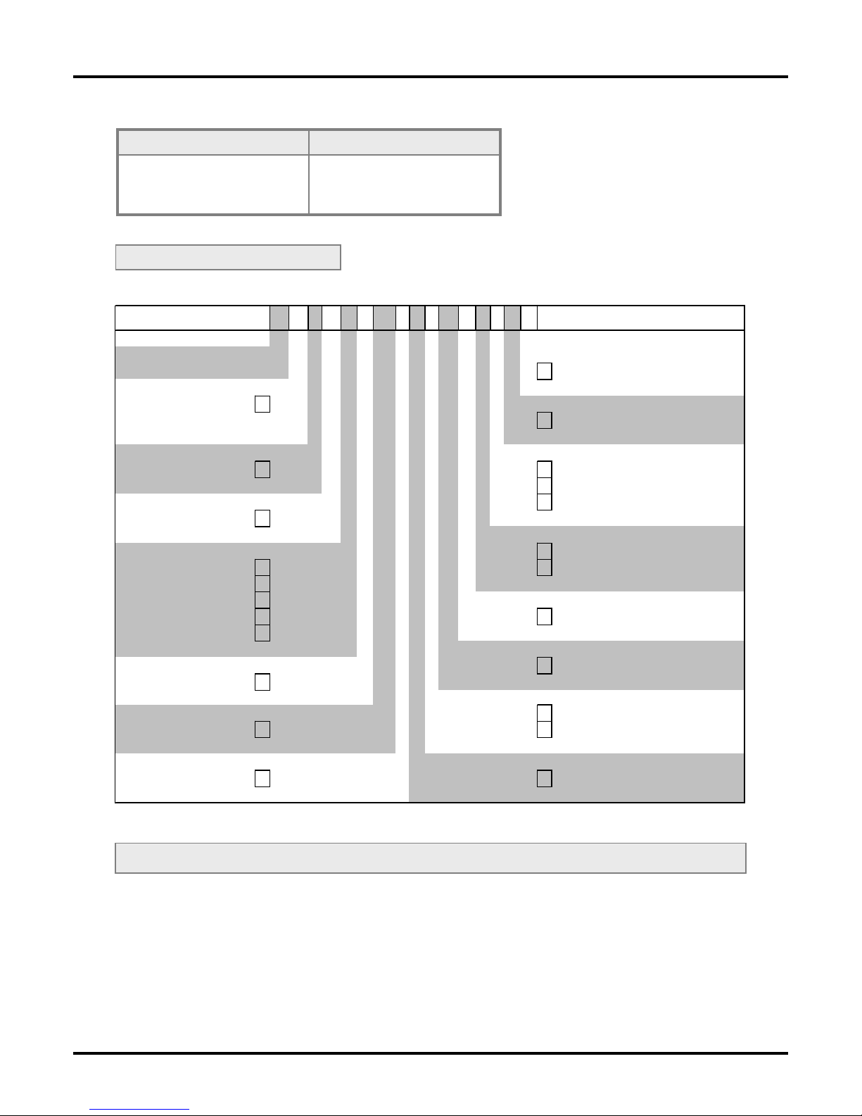
Options – breakdown of order code:
M3-3VR5B.0H04.S72BD
Standard type M-line Dimension
D physical unit
Installation depth mm
144 mm (154 mm ), 3
Version
incl. plug-in terminal B B
Housing size Switching points
B96xH24xD120 mm 3 0 no switc hing point
1 1 relay output
Type of display
2 2 relay output s
V, A V
Protection class
Display colours
1 without keypad, operation via PM-Tool
Blue B 7 IP65 / plug-in terminal
Green G
Red R
Voltage supply
Tricolor (red, green, orange) T S 100-240 VAC
Orange Y
Mea suring input
Numb er of digits
4 AC voltage / AC current, TRMS
5-digit 5
Analog output
Digit height
0 without
14 mm
B
X 0-10 VDC, 0/4-20 mA
Digital input Special measuring input
without 0 H
300 VAC, 5 AA C

Contents
1
1. Brief description 2
2. Safety advices 2
3. Assembly 3
4. Electrical connection 4
5. Description of function and operation 5
5.1. Programming software PM-TOOL 6
6. Setting up the device 7
6.1. Switching on 7
6.2. Standard parameterisation (flat operation level) 7
Value assignment for the triggering of the signal input
6.3. Programming interlock „RUN“ 10
Activation/Deactivation of the programming interlock or change into professional
or flat operation level
6.4. Extended parametersation (professional operation level) 11
6.4.1. Signal input parameters „INP“ 11
Value assignment for the triggering of the signal input incl. linearisation
6.4.2. General device parameters „FCT“14
Superior device functions like Hold, Tara, min/max permanent, setpoint value function /
nominal value function, averaging, brightness control, as well as the control of the
keyboard layout
6.4.3. Safety parameters „COD“ 18
Assignment of user and master code to lock or to receive access to defined parameter such as
analog output and alarms, etc
6.4.4. Analog parameters „Out“ 19
Analog outpur functions
6.4.5. Relay functions „rel“ 21
Parameter for setpoint definition
6.4.6. Alarm parameters „AL1…AL4“ 22
Actuator and dependencies of the alarms
6.4.7. Totaliser (Volume metering) „tot“24
Parameter for calculation of the sum function
7. Reset to factory settings 25
Reset parameters onto the delivery state
8. Alarms / Relays 26
Functional principle of the switching outputs
9. Sensor aligment 27
Diagram of functional sequences for sensors with existing adjustable resistor
10. Technical data 28
11. Error elimination 30

1. Brief description
2
1. Brief description / 2. Safety advices
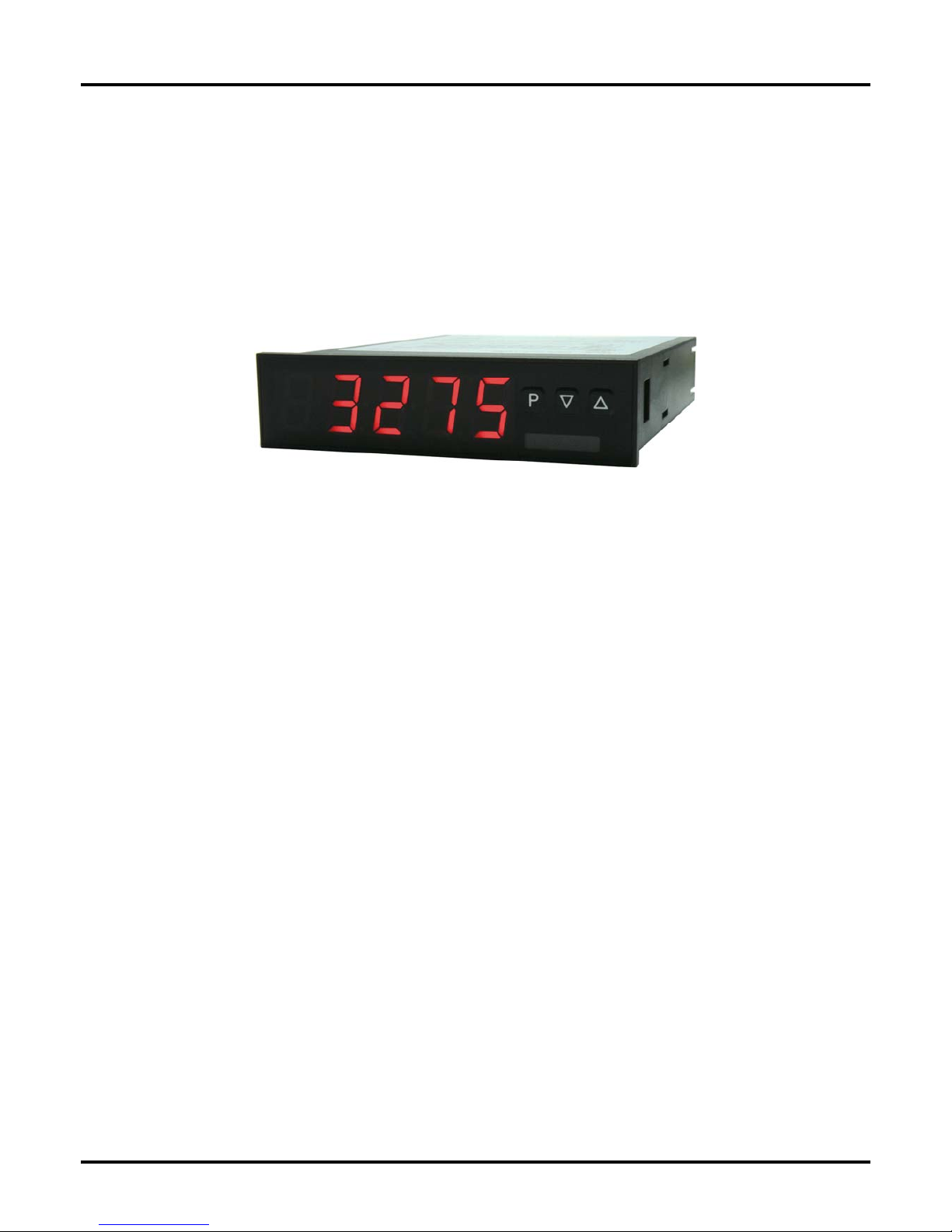
The panel meter instrument M3-34H is a 5-digit device for AC current / AC voltage signals (TRMS) and a
visual threshold value monitoring via the display. The configuration happens via three keys at the front or by
the optional PC software PM-TOOL. The integrated programming interlock prevents unrequested changes
of parameters and can be unlocked again with an individual code. Optional the following functions are
available: one analog output and interfaces for further evaluating in the unit.
With help of the two galvanic isolated setpoints (optional), free adjustable limit values can be controlled and
reported to a superior master display.
The electrical connection is done via plug-in terminals on the back side.
Selcetable functions like e.g. the recall of the min/max-value, an averaging of the measuring signals, a
nominal presetting or setpoint presetting, a direct threshold value regulation during operation mode and
further measuring setpoints for linearisation, complete the modern device concept.
2. Safety advices
Please read the following safety advice and the assembly chapter 2 before installation and keep it for future
reference.
Proper use
The M3-34H-device is designed for the evaluation and display of sensor signals.
Danger! Careless use or improper operation can result in
personal injury and/or cause damage to the equipment.
Control of the device
The panel meters are checked before dispatch and sent out in perfect condition. Should there be any visible
damage, we recommend close examination of the packaging. Please inform the supplier immediately of any
damage.
Installation
The M3-34H-device must be installed by a suitably qualified specialist (e.g. with a qualification in industrial
electronics).
Notes on installation
• There must be no magnetic or electric fields in the vicinity of the device, e.g. due to transformers, mobile
phones or electrostatic discharge.
• The fuse rating of the supply voltage should not exceed a value of 6A N.B. fuse.
• Do not install inductive consumers (relays, solenoid valves etc.) near the device and suppress any
interference with the aid of RC spark extinguishing combinations or free-wheeling diodes.
• Keep input, output and supply lines separate from one another and do not lay them parallel with each other.
Position “go” and “return lines” next to one another. Where possible use twisted pair. So, you receive best
measuring results.
• Screen off and twist sensor lines. Do not lay current-carrying lines in the vicinity. Connect the screening on
one side on a suitable potential equaliser (normally signal ground).
• The device is not suitable for installation in areas where there is a risk of explosion.
• Any electrical connection deviating from the connection diagram can endanger human life and/or can destroy
the equipment.
• The terminal area of the devices is part of the service. Here electrostatic discharge needs to be avoided.
Attention! High voltages can cause dangerous body currents.
• Galvanic isolated potentials within one complex need to be placed on a appropriate point (normally earth or
machines ground). So, a lower disturbance sensibility against impacted energy can be reached and
dangerous potentials, that can occur on long lines or due to faulty wiring, can be avoided.
3. Assembly
3
3. Assembly
Please read the Safety advices on page 2 before installation and keep this user manual for future reference.
S
e
a
l
i
n
g
I
n
s
t
a
l
l
a
t
i
o
n
d
e
p
t
h
i
n
c
l
u
d
i
n
g
p
l
u
g
-
i
n
t
e
r
m
i
n
a
l
(
d
e
p
t
h
d
e
p
e
n
d
s
o
n
o
p
t
i
o
n
s
)
1
4
5
,
0
(
1
5
4
,
0
)
9
6
,
0
24,0
Gap for physical uni t
3
,
0
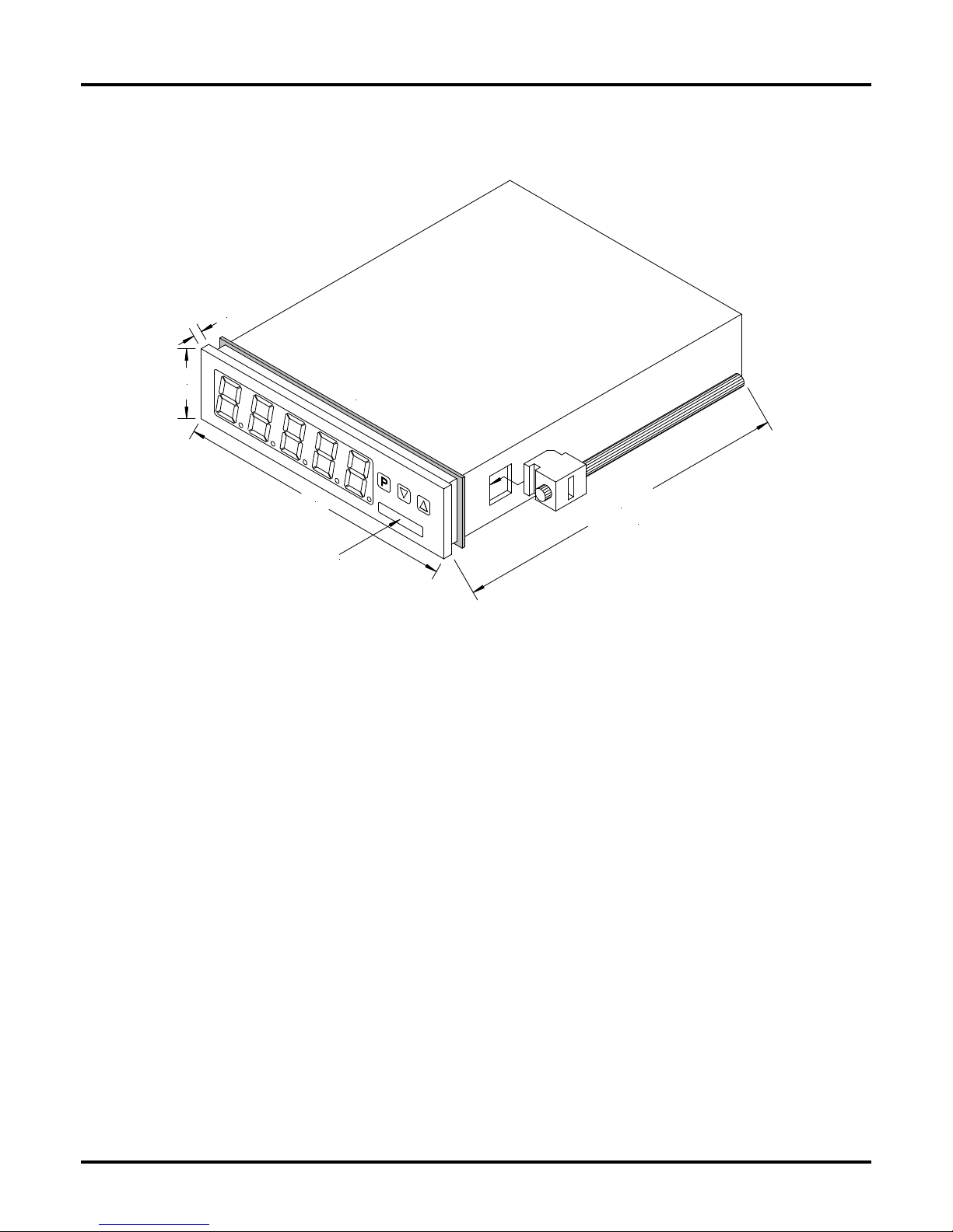
1. After removing the fixing elements, insert the device.
2. Check the seal to make sure it fits securely.
3. Click the fixing elements back into place and tighten the clamping screws by hand. Then use a
screwdriver to tighten them another half a turn.
CAUTION! The torque should not exceed 0.1 Nm!
The dimension symbols can be exchanged before installation via a channel on the side!
4. Electrical connection
4
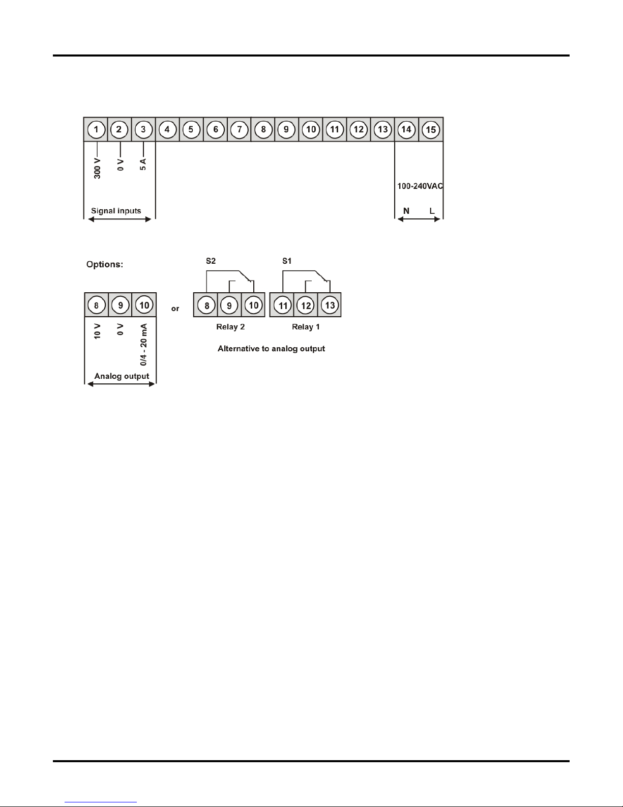
4. Electrical connection
Type M3-3VR5B.0H04.S70BD supply 100-240 VAC 50/60Hz, DC ±10%
5. Description of function and operation
5
5. Description of function and operation
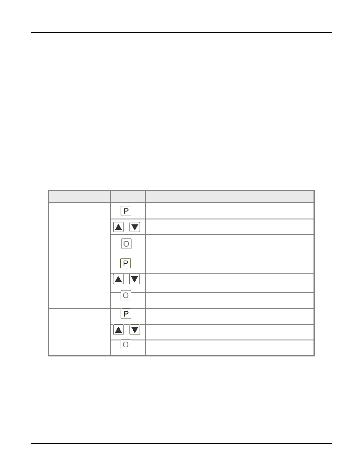
Operation
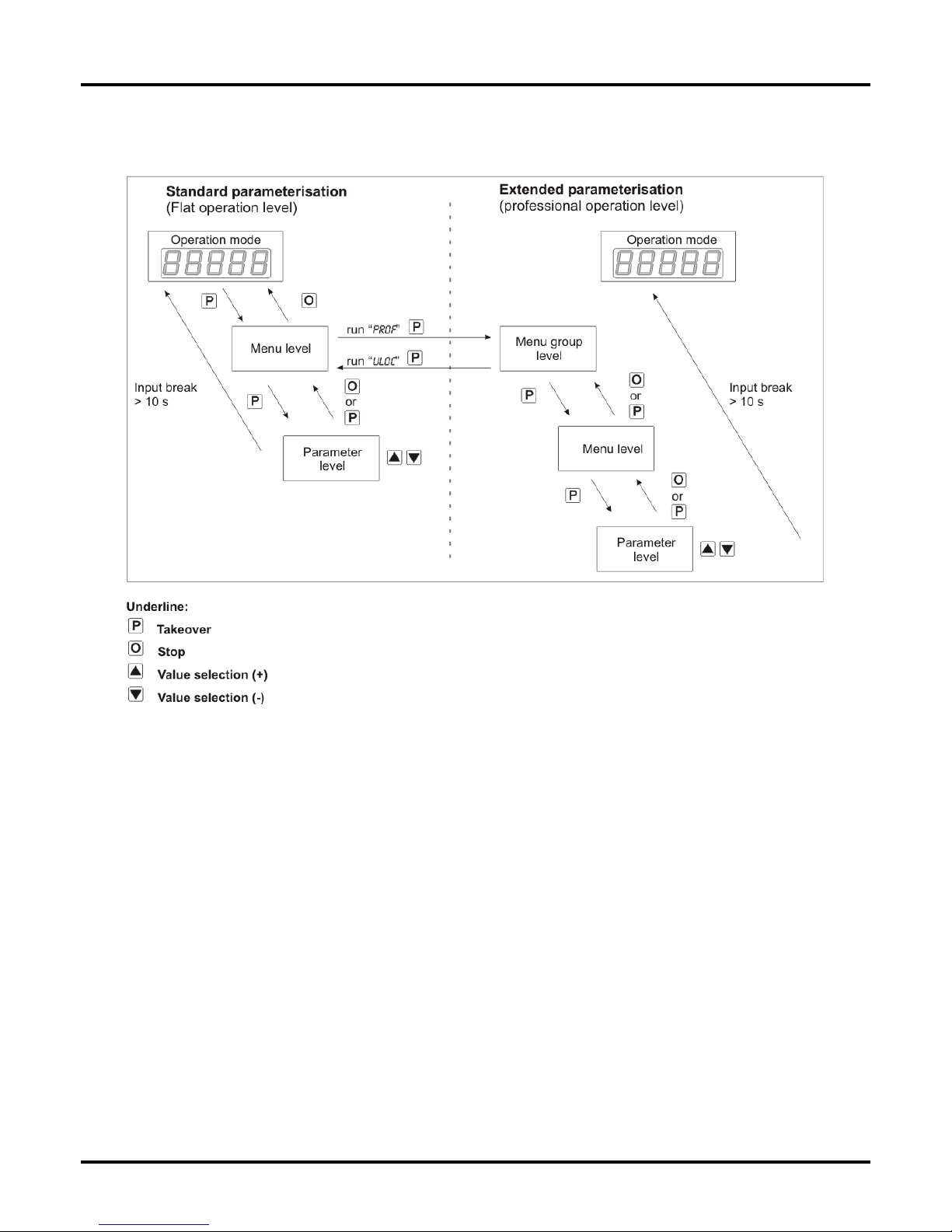
The operation is divided into three different levels.
Menu level (delivery status)
This level was designed for the standard settings of the device. Only menu items which are sufficent to set
the device into operation are displayed. To get into the professional level, run through the menu level and
parameterise prof under menu item RUN.
Menu group level (complete function volume)
Suited for complex applications as e.g. linkage of alarms, setpoint treatment, totaliser function etc. In this
level function groups which allow an extended parameterisation of the standard settings are availabe. To
leave the menu group level, run through this level and parameterise uloc under menu item RUN.
Parameterisation level:
Parameter deposited in the menu item can here be parameterised. Functions, that can be changed or
adjusted, are always signalised by a flashing of the display. Settings that are made in the parameterisation
level are confirmed with [P] and thus safed. Pressing the [O]-key leads to a break-off of the value input
and to a change into the menu level. All adjustments are saved automatically by the device and changes
into operating mode, if no further key operation is done within the next 10 seconds.
Keys for up and down navigation in the menu group level.
Change to menu level.
Change into menu level or break-off in value input.
Parameterisation-
level
Adjustment of the value / the setting.
Keys for up and down navigation in the menu level.
DescriptionKey
Change into operation mode or back into menu level.
To confirm the changes made at the parameterisation
level.
Change into operation mode.
Change to parameterisation level and deposited values.
Menu-group-level
Menu-level
Level
6
5. Description of function and operation
Function chart:
5.1 Parameterisation software PM-TOOL:
Part of the PM-TOOL are the software on CD and an USB-cable with device adapter. The connection
happens via a 4-pole micromatch-plug on the back side of the device, to the PC-side the connection
happens via an USB plug.
System requirements: PC incl. USB interface
Software: Windows XP, Windows VISTA
With this tool the device configuration can be generated, omitted and saved on the PC. The parameters can
be changed via the easy to handle program surface, whereat the operating mode and the possible selection
options can be preset by the program.
7
6.1. Switching on
Once the installation is complete, start the device by applying the voltage supply. Before, check once again
that all electrical connections are correct.
Starting sequence
For 1 second during the switching-on process, the segment test (8 8 8 8 8) is displayed followed by an
indication of the software type and, after that, also for 1 second the software version. After the starting
sequence, the device switches to operation/display mode.
6.2. Standard parameterisation: (Flat operation level)
To parameterise the display, press the [P]-key in operating mode for 1 second. The display then changes to
the menu level with the first menu item TYPE.
6. Setting up the device
6. Setting up the device
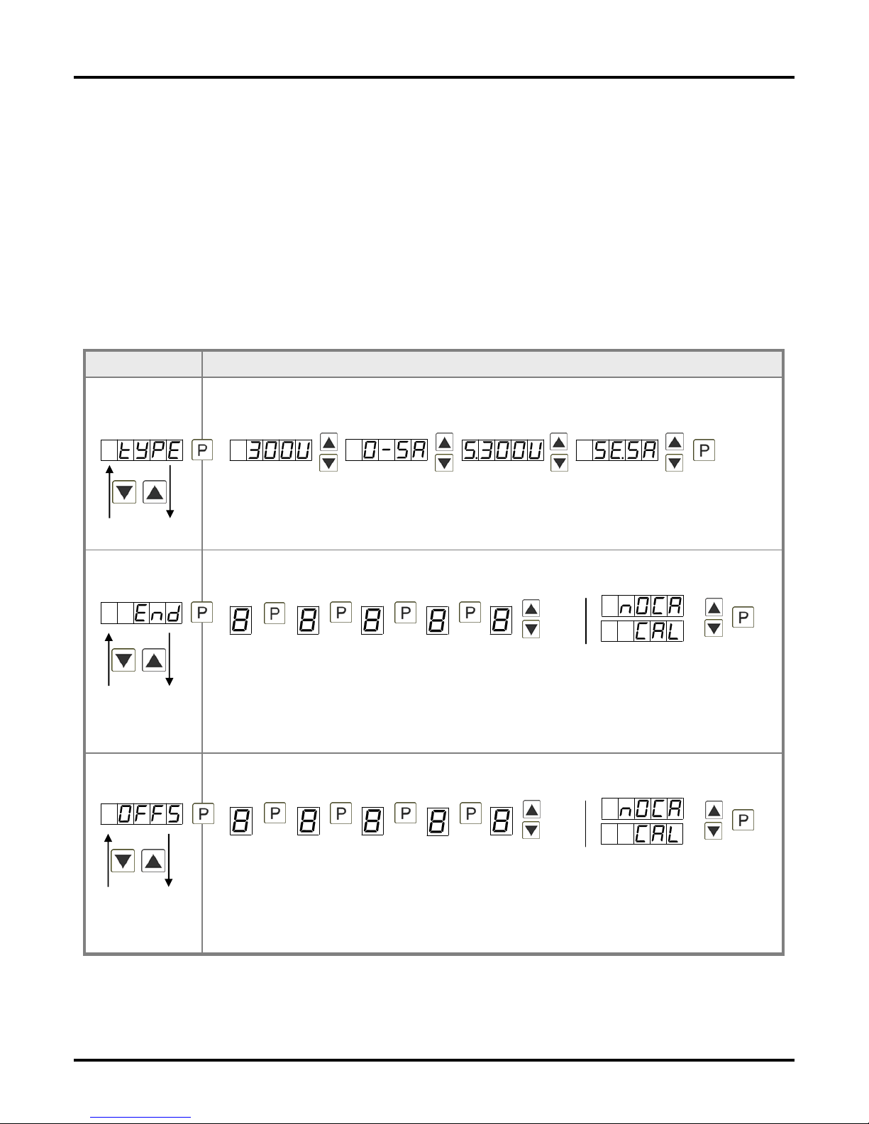
Setting the end value of the measuring range, END:
Default: 10000
Set the end value from the smallest to the highest digit with [▲] [▼] and confirm each digit with
[P]. A minus sign can only be parameterized on the highest value digit. After the last digit, the
display switches back to the menu level. If Sens was selected as input option, you can only
select between noca and cal. With noca, only the previously set display value is taken over, and
with cal, the device takes over both the display value and the analogue input value.
Setting the start/offset value of the measuring range, offs:
Default: 0
Enter the start/offset value from the smallest to the highest digit with [▲] [▼] and confirm each
digit with [P]. After the last digit the display switches back to the menu level. If Sens was
selected as input option, you can only select between noca and cal. With noca, only the
previously set display value is taken over, and with cal, the device takes over both the display
value and the analogue input value.
Selection of the input signal, tYPE:
Default: s.30ou
Available as measuring input options are 0-300 VAC or 0-5 AAC signals as works calibration
(without application of the sensor signal) and S.300v and se.5a as sensor calibration (with the
sensor applied). Select with [▲] [▼] and confirm the selection with [P].
Parameterisation levelMenu level
8
6. Setting up the device
Setting up the initial value of the analog output, Out.OF:
Default: 00000
The final value is adjusted from the smallest digit to the highest digit with [▲] [▼] and digit by
digit confirmed with [P]. A minus sign can only be parameterised on the highest digit. After the
last digit, the device changes back into menu level.
Setting up the final value of the analog output, Out.En:
Default: 10000
The final value is adjusted from the smallest digit to the highest digit with [▲] [▼] and digit by
digit confirmed with [P]. A minus sign can only be parameterised on the highest digit. After the
last digit, the device changes back into menu level.
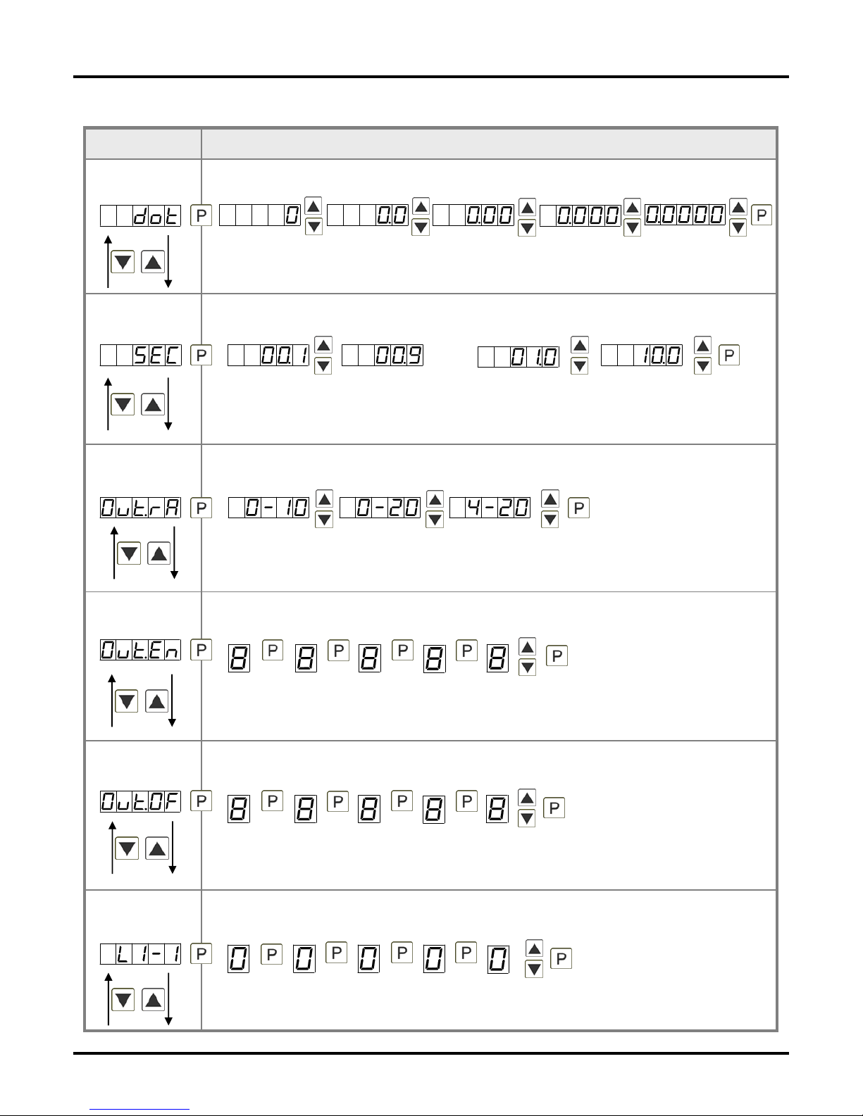
Threshold values / limits, LI-1:
Default: 2000
This value defines the threshold, that activates/deactivates an alarm.
Selection of analog output, Out.rA:
Default: 4-20
Three output signals are available: 0-10 VDC, 0-20 mA and 4-20 mA, with this function, the
demanded signal is selected.
Setting up the display time, SEC:
Default: 1.0
The display time is set with [▲] [▼]. The display moves up in increments of 0.1 up to 1 second
and in increments of 1.0 up to 10.0 seconds. Confirm the selection by pressing the [P] button.
The display then switches back to the menu level again.
Setting the decimal point, dot:
Default: 0
The decimal point on the display can be moved with [▲] [▼] and confirmed with [P]. The
display then switches back to the menu level again.
Parameterisation levelMenu level
then
 Loading...