

montpellier MTE50FW Installation And Operating Instructions Manual
50cm Twin Cavity Solid Plate Cooker
MTE50FW
Please read these instructions carefully before attempting to install or use this appliance.
We recommend that you keep these instructions in a safe place for future reference.
Installation and Operating Instructions
THE PERFECT BALANCE OF FUNCTION AND STYLE
LAUNDRY - DISHWASHING - COOKING - COOLING

Thank you for choosing this Montpellier freestanding cooker.
Our cookers have been designed to provide you with the best combination of style, reliability and performance to
give you years of trouble-free use.
You may be familiar with a similar product, but please take time to read these instructions carefully before installing
or using your freestanding cooker to ensure you get the most from your purchase.
We recommend that you keep this manual in a safe place for future reference.
Your cooker is covered by a comprehensive two year Parts & Labour Guarantee.
In the unlikely event that you experience a problem with your Integrated
Dishwasher, you can rest assured that you are fully protected against the cost
of repairs for the first 24 months . Please note that any claim must be
accompanied by the model reference number, serial number and proof of
purchase.
To activate your guarantee, you will need your product serial number. This can
be found on the rear of the machine.
There are two ways to register your Guarantee:
• Online: Visit the Support page on our website and complete the online Product
Registration form. www.montpellier-appliances.com
•
By Post: Simply detach and ll in the form provided, attach a stamp and send
it in the post. Don’t forget to include your e-mail address so that we can send
conrmation through to you.
Welcome
Note: We are unable to take registrations over the phone.
ACROSS ALL OUR MODELS
YEAR
GUARANTEE
PA R TS & L AB OU R
www.montpellier-appliances.com
3
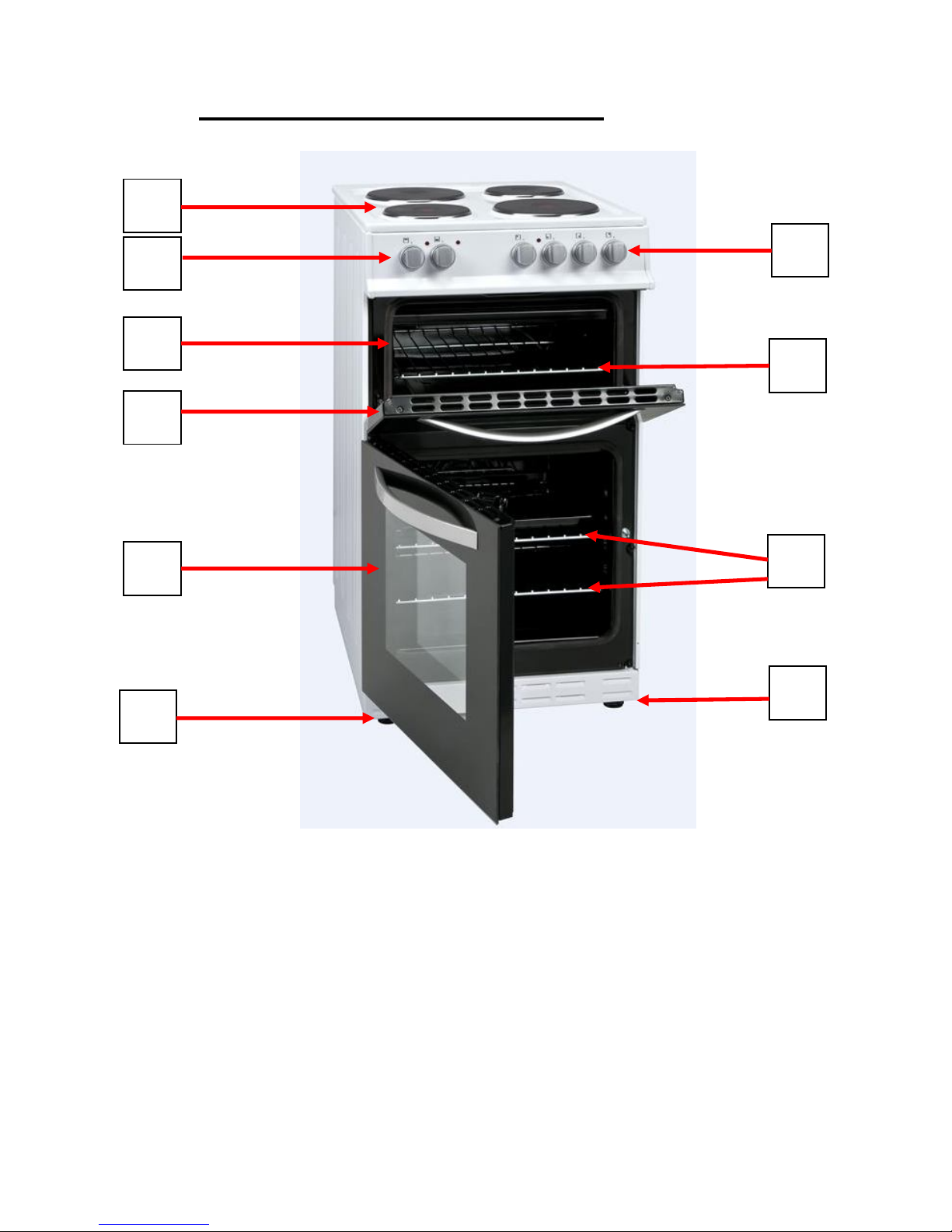
Description Of The Appliance
1.
7.
2.
3.
4.
5.
6.
8.
9.
9.
1. Cook Zones x 4
2. Grill & Oven Control Knobs (plus 2 x operation lights)
3. Cook Zone Control Knobs (plus 1 x operation light)
4. Grill Compartment
5. Rack
6. Grill Compartment Door
7. Oven Door
8. Oven Racks
9. Feet

4
CONTENTS:
Section 1. Installation
Section 2. Safety Advice
Section 3. Operating the Appliance
Section 4. Maintenance

5
S
ection 1. Installation
• Remove all packaging, protective film and/or securing tape
from the appliance.
• Position the appliance in a dry atmosphere.
• The following instructions are provided as a guide for
installation – your installer will carry out the installation in
accordance with the current regulations.
• Your installer will connect the power cable in accordance with
the current regulations.
1.1. Positioning the Appliance
• Position the appliance as shown in the diagram below.
• Ensure an air gap of at least 2cm at the rear of the appliance.
• If positioned between kitchen cabinets, the height of the
cabinets/work-tops must not exceed the height of the cooker.
• If positioned between kitchen cabinets, the cabinet material
must be compliant with the relevant heat resistant standards.
• You must ensure a minimum gap of 65cm between the top of
the appliance and a cooker hood. The gap must be 70cm if
there is no cooker hood installed above the appliance.
• You must ensure that the appliance can be easily removed for
servicing.

6
1.2. Electrical Connection
This appliance must be ‘hard wired’ into a suitable
fused spur adjacent to the appliance housing, by a Qualified
Electrician. Please note that a switchable spur should be accessible
above the work surface in order that the power can be turned
off by the consumer.
Your installer will supply and use the appropriate diameter of
electrical cable based on the Power Rating of the appliance as
shown on the Rating Label affixed to the appliance.
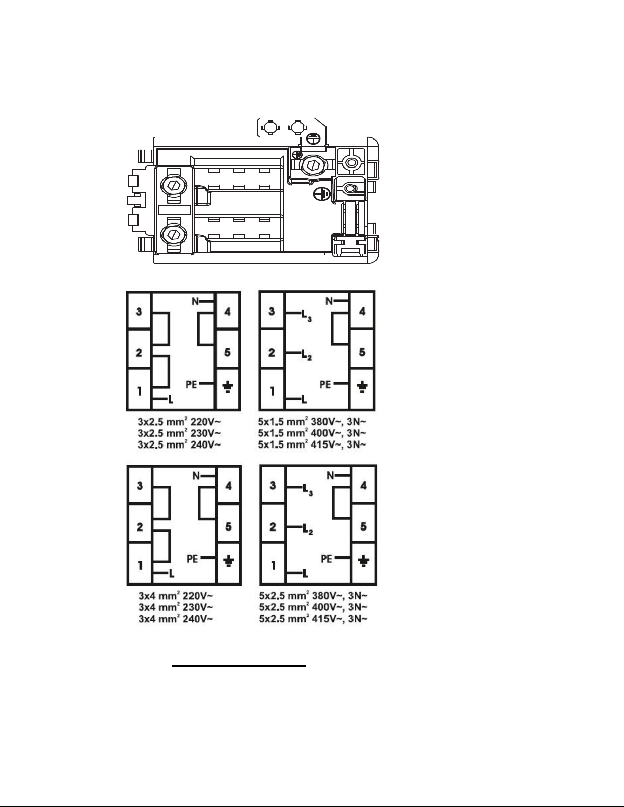
7
Electrical Connection Diagram:
1.3. Level the Appliance
Finally, ensure that the appliance is level by adjusting the feet
positioned at the base.
L
N
PE
 Loading...