

montpellier MTG50LW, MSG60W, MSG50 Installation And Operating Instruction
50cm Twin Cavity Gas Cooker
M
TG50LW - White with Lid
Please read these instructions carefully before attempting to install or use this appliance.
We recommend that you keep these instructions in a safe place for future reference.
Installation and Operating Instructions
THE PERFECT BALANCE OF FUNCTION AND STYLE
LAUNDRY - DISHWASHING - COOKING - COOLING

Thank you for choosing this Montpellier Freestanding Cooker.
Our
Cookers has been designed to provide you with the best combination of style, reliability and performance to
give you years of trouble-free use.
You may be familiar with a similar product, but please take time to read these instructions carefully before installing
or using your Freestanding Cooker to ensure you get the most from your purchase.
We recommend that you keep this manual in a safe place for future reference.
Your
Freestanding Cooker is covered by a comprehensive two year Parts & Labour
Guarantee. In the unlikely event that you experience a problem with your Cooker,
you can rest assured that you are fully protected against the cost of repairs for the
first 24 months . Please note that any claim must be accompanied by the model
reference number, serial number and proof of purchase.
To activate your guarantee, you will need your product serial number. This can be
found on the rear of the machine.
There are two ways to register your Guarantee:
•
Online: Visit the Support page on our website and complete the online Product
Registration form. www.montpellier-appliances.com
•
By Post: Simply detach and ll in the form provided, attach a stamp and send
it in the post. Don’t forget to include your e-mail address so that we can send
conrmation through to you.
Welcome
Note: We are unable to take registrations over the phone.
ACROSS ALL OUR MODELS
YEAR
GUARANTEE
PA R TS & L AB OU R
www.montpellier-appliances.com
4
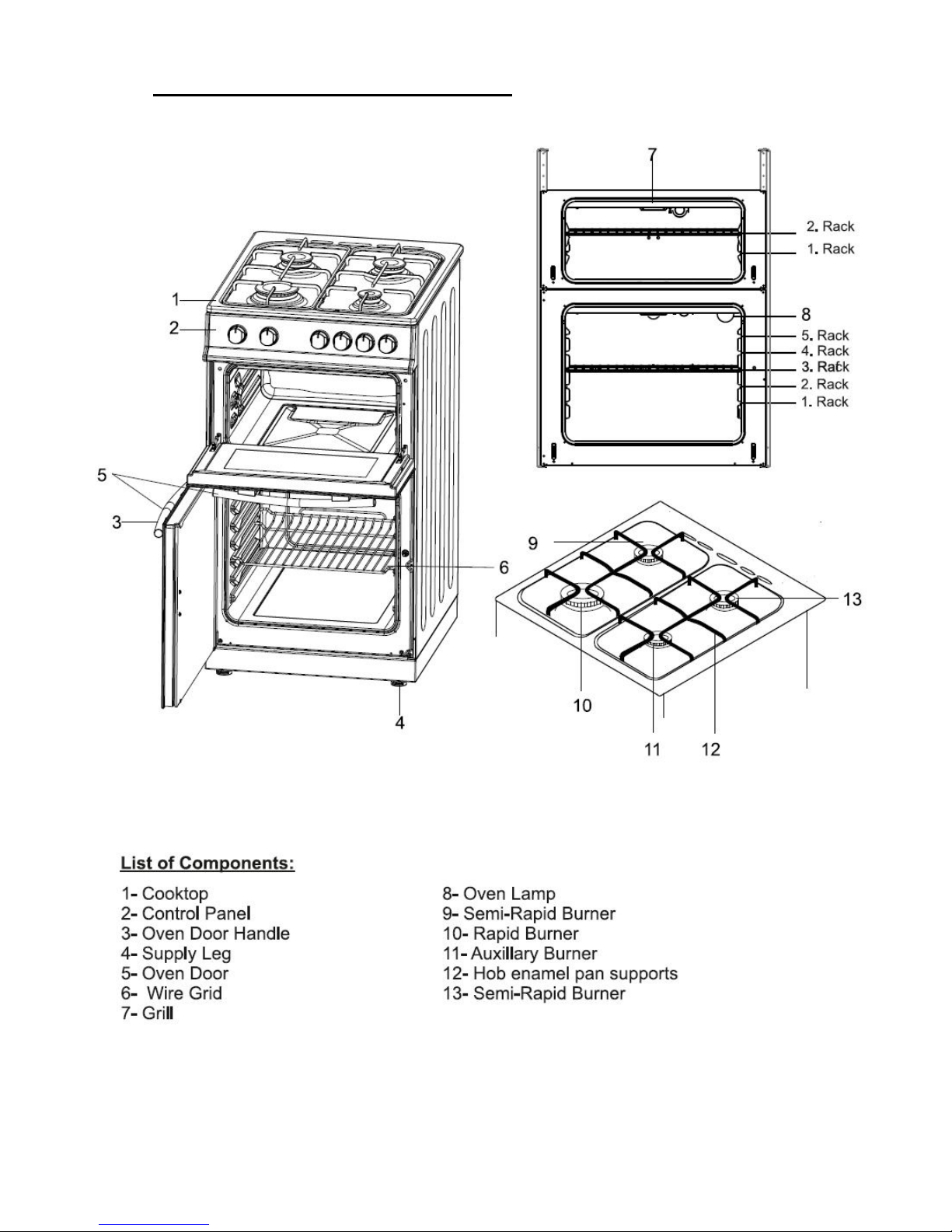
Description Of The Appliance
Your Oven may be fitted with a fold-down lid (Not Shown above)
(Line Drawings indicative of model supplied)
(N.B. Model supplied my not have all features shown in this User Manual).

5
CONTENTS:
Section 1. Installation
Section 2. Safety Advice
Section 3. Operating the Appliance
Section 4. Maintenance
6
S
ection 1. Installation
- This appliance must be installed by a ‘Gas Safe’ gas engineer.
- Remove all packaging, protective film and securing tape from
the appliance.
- Position the appliance in a dry atmosphere.
- The following dimensions are provided as a guide for
installation – your installer will carry out the installation in
accordance with the current regulations.
- Your ‘Gas Safe’ gas engineer will connect the cooker in
accordance with the current regulations.
To install this appliance, please proceed as follows:
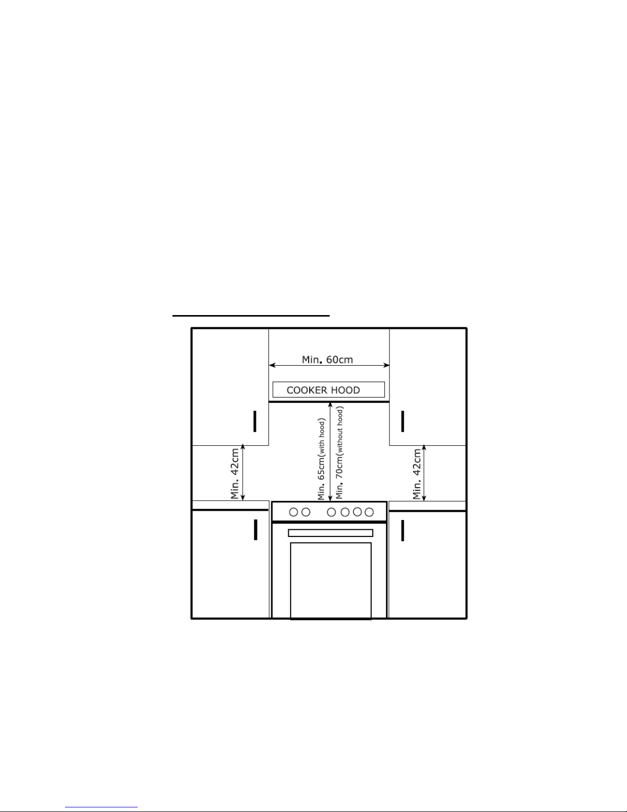
1.1. Positioning the Cooker
You must ensure a minimum gap of 2cm between the back
of the appliance and the rear wall to allow for ventilation. You
must ensure a minimum distance of 70cm between the
hotplate and overhanging cupboards or a cooker hood (as
shown above).

7
Adjust the height and stability of the cooker by adjusting the
two front feet as shown below. Rotate in a clockwise direction
to decrease the height and in an anti-clockwise direction to
increase the height.
1.2. Electrical Connection
This appliance can be fitted with a 13 Amp plug and plugged
into a standard, switchable 13 Amp socket.
Alternatively, the product can be ‘hard wired’ into a suitable
fused spur adjacent to the appliance housing. In this case the
product must be installed by a Qualified Electrician. Please
note that a switchable spur should be accessible above the
work surface in order that the power can be turned off.

8
1.3. Gas Connection
THE GAS CONNECTION MUST BE CARRIED OUT BY A ‘GASSAFE’ REGISTERED GAS ENGINEER!
Connection to the gas supply should be with either rigid or
semi-rigid pipe, i.e. steel or copper. The connection should be
suitable for connecting to RC 1/2 (1/2 BSP male thread).
When the final connection has been made, it is essential that
a thorough leak test is carried out on the cooker and
installation. Ensure that the main connection pipe does not
exert any strain on the cooker. When a flexible tube is used,
make sure that it does not come into contact with hot areas
or adjacent housing units.
It is important to install the elbow correctly, with the shoulder
on the end of the thread, fitted to the cooker connecting pipe.
Failure to ensure the correct assembly will cause leakage of
gas.
 Loading...