

Montigo RFK3002 User Manual
Optional Fans
US
Optional Fan Kit
Installing the RFK3002/3004 Fan Kit
for use with:
B34 DV2; B34 DV2-F
B38 DV2; B38 DV2-F
C
WARNING
When installing the replace - gas lines, ttings,
accessories or any other objects cannot impede the
proper movement of the door buckles.
CAUTION
Ensure that all power to the appliance is off at the electrical breaker or fuse
before beginning installation. Ensure gas is turned off at the shutoff valve before
beginning installation.
This kit should be installed by a qualied person.
®
Check local codes and read all instructions prior to installation.
PPO Box
Fans
General Information
This blower kit is for installation with the models listed above.
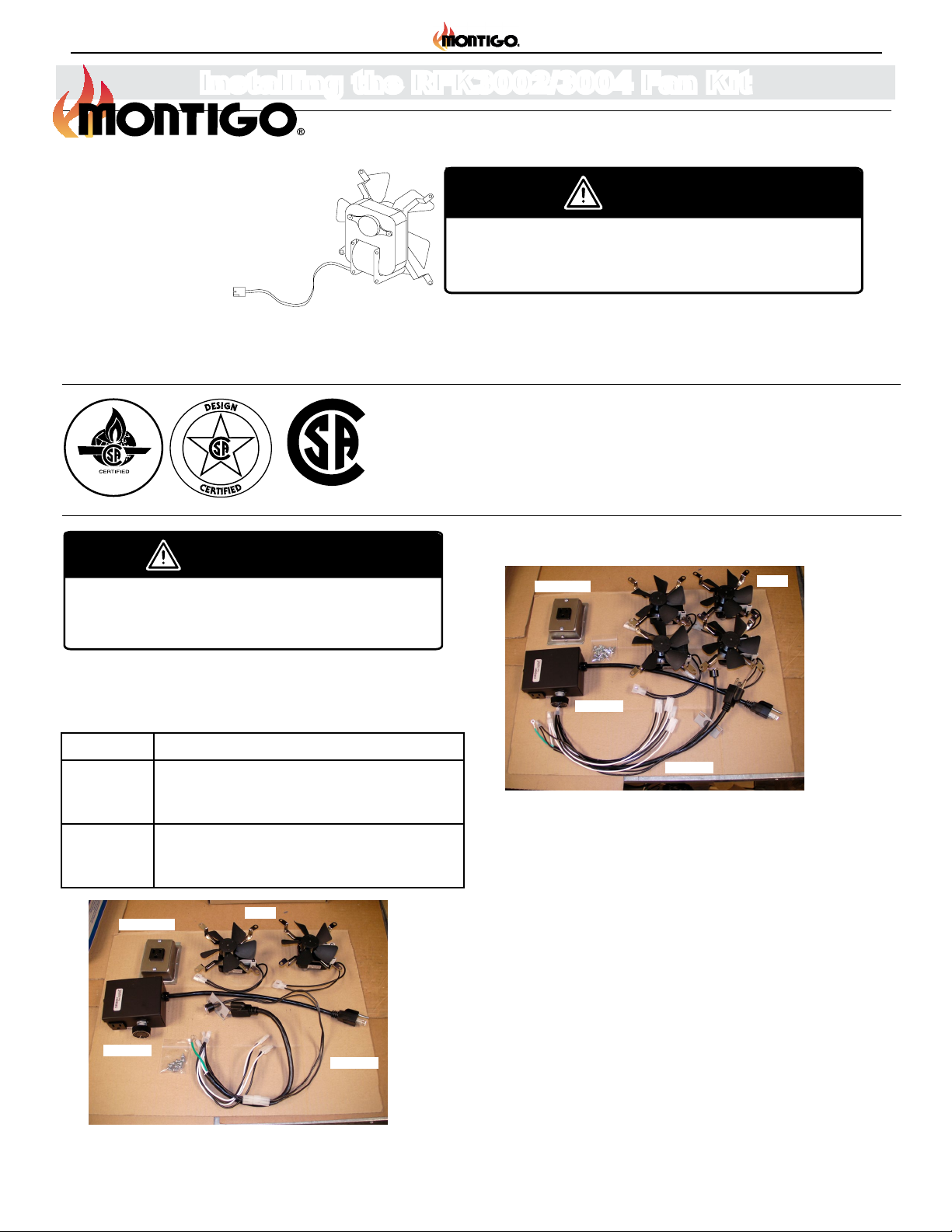
KIT # Contents
RFK3002 2 fans, 1 PPO box, 1 wire harness (PCH2), speed
controller (DRB001), 10 screws (HW2054),
heat-activated control and speed control
RFK3004 4 fans, 1 PPO box, 1 wire harness (PCH4), speed
controller (DRB001), 20 screws (HW2054),
heat-activated control and speed control
PPO Box
DRB001
Fans
PCH2
DRB001
PCH4
Figure 2 Kit contents (RFK3004).
Before You Begin
• Please read all instructions carefully
• We strongly recomment that all electrical service work be performed by a qualied electrical contractor.
• Check to ensure that all components required for installation are
included in your package.
Figure 1
Page 1
Kit contents (RFK3002).
XT0018 - 150324
Optional Fan Kit
Operation
1. Turn on electrical power at the breaker or fuse.
2. If the fans are manually controlled (not connected to a heat
sensor), turn on the fans' wall switch to activate the fans.
To stop the fans, turn off the wall switch.
3. If the fans are heat-activated, they will automatically switch
after the fireplace's main burner has been lit and the
temperature has risen. The time lapse between lighting the
fireplace and fan activation will vary, depending on the model.
The fans will automatically shut off as the fireplace cools.
Optional Fan Kits
Install each fan motor with the blades facing the 4" round fan
opening. Attach the mounting legs by screwing into the pilot holes
around the fan opening. Spin the fan blades by hand to ensure
they don't hit the fan opening. (See Figure 2.)
Fan Motor Installation
Installation
Installation
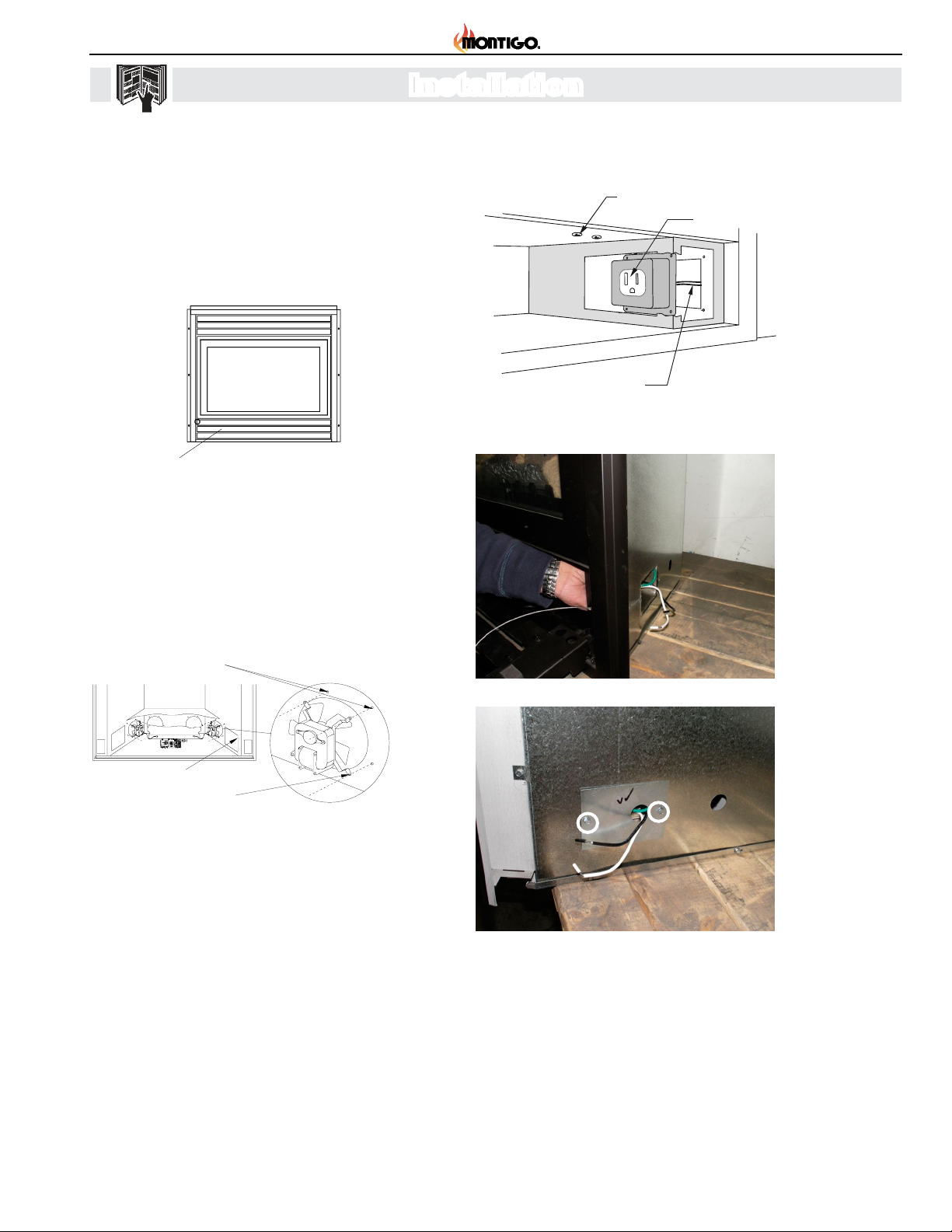
1. Accessing the Control Compartment
• Flip down the lower horizontal trims of the
replace Figure 3.)
Lower horizontal trim
Figure 3 Accessing control compartment.
2. Fan Motor Installation
• Install each fan motor with the blades facing the 4" round fan
opening. Attach the mounting legs by screwing into the pilot
holes around the fan opening. Spin the fan blades by hand
to ensure they don't hit the fan opening. (See Figure 4.)
Heat sensor
locator screw
To electrical
supply
Figure 5 Installing the PPO Box.
PPO box
Pilot Holes
Access for
electrical connections
Mounting Legs
Figure 4 Cutaway view of control compartment showing fan
motor installation.
3. Installing the Power Box (only for B34DV2, B38DV2)
• The PPO box connects the fans to the household electrical
supply. In some models this box has been factory-installed,
and is located at the bottom right corner of the replace.
• If the PPO box has not been factory installed, ensure that
the household electrical supply is shutoff at the breaker or
fuse, and connect the two wire leads from the box to the
household electrical supply. Insert the PPO box into the
square hole in the right-hand side of the control compartment
and screw into place using self drilling hex screws as shown
in Figure 5, 6 and 7.
Figure 6 Installing the PPO Box (from outside of replace).
Figure 7 Lead wires that connect to household electrical
supply.
Page 2
XT0018 - 150324
 Loading...