

Montigo Panorama M38DV-PRC, Panorama M38DV-PRC-I Operation Manual
Installation
®
C US
Operation &
Maintenance
M38DV-PRC
Panorama
Direct-Vented
Gas Fireplace
Safety Notice:
Glass doors on gas replaces are
extremely hot while the replaces is on
and remain hot even after the replace
has been turned off. Safety screens
are available and can reduce the risks
of severe burns. Please keep children
away from the replace at all times.
Warning:
Improper installation, adjustment,
alteration, service or maintenance can
cause injury or property damage. Refer to
this manual. For assistance or additional
information consult a qualied installer,
service agency or the gas supplier.
For Your Safety:
Do not store o r u se
gasoline or other ammable
vapors and liquids in the
vicinity of this or any other
appliance.
What To Do If You Smell Gas:
• Do not try to light any appliance.
• Do not touch any electrical switch; do not use any phone in your building.
• Immediately call your gas supplier from a neighbor's phone. Follow the gas
supplier's instructions.
• If you cannot reach your gas supplier, call the re department.
Check local codes and read all
instructions prior to installation.
Installer: Leave this manual
with the appliance.
Consumer: Leave this man-
ual for future reference.
Panorama Direct Vented Fireplace
Table Of Contents
Introduction ............................................................................... 2
Installation ..........................................................................3 - 12
Installing the Fireplace Shell .......................................... 3
Installing the Gasline ......................................................
The Remote Switch ........................................................ 4
Direct Vent Installation ................................................... 4
General Requirements ...................................... 4
Terminations ...................................................... 5
Horizontal Venting Runs .................................... 6
Vertical Venting Runs ........................................ 7
Construction around the fireplace
Facing .............................................................. 8
Mantels and Surrounds ..................................... 8
Wiring ............................................................................ 9
Fans ............................................................................... 9
Removing and Installing the Doors .............................. 10
Operation ............................................................................10-13
Burner Adjustment...................................................11-13
Maintenance ....................................................................... 14-15
Warranty .................................................................................. 16
Appendix A - Termination Locations ....................................... 17
Appendix B - Spare Parts & Accessories ................................ 18
Introduction
The 38 Series Direct Vent - Panorama is a multi-sided Gas Fireplace
with an adjustable center burner and air-circulating fans. It is available in two models:
Model M38DV-PRC (continuous pilot)
Model M38DV-PRC-I (intermittent pilot)
4
This manual covers installation, operation and maintenance. Lighting, operation and care of this fireplace can be easily performed by
the homeowner. However, all installation and service work should be
performed by a qualified or licensed installer, plumber, or gasfitter
who is qualified or licensed by the state, province, region, or governing body in which the appliance is being installed.
This manual covers both models and unless otherwise specified, the
designation M38DV-PRC refers to both models. Sections which are
specific to a particular model are marked with a sym
bol, plus the appropriate model number.
The M38DV-PRC is rated for:
Natural Gas at 30,000 BTU/H (8.78 Kilowatts) max. input, and
24,000 BTU/H (6.86 Kilowatts) min. input
Propane at 28,000 BTU/H (8.20 Kilowatts) max. input, and
22,000 BTU/H (6.40 Kilowatts) min. input
The Montigo warranty will be voided by, and Montigo disclaims any
responsibility for, the following actions:
Modification of the fireplace and/or components including Direct-
Vent assembly or glass doors.
Use of any component part not manufactured or approved by
Montigo in combination with this Montigo fireplace system.
Installation other than as instructed in this manual.
Consult your local Gas Inspection Branch on installation requirements for factory-built gas fireplaces. Installation & repairs should be
done by a qualified contractor.
Installations in Canada must conform to the current CAN/CGA
B-149.1 and .2 Gas Installation Code and local regulations. This fire-
place's fans must be electrically grounded in accordance with CSA
C22.1 Canadian Electrical Code Part 1 and/or Local Codes.
Installations in the USA must conform to local codes, or in the
absense of local codes to the National Fuel Gas Code, ANSI Z223.1-
1988. The fans must be grounded in accordance with local codes
or, in the absence of local codes, with the National Electrical Code,
-
Page 2
CAUTIONS
Due to its high operating temperatures, the appliance
should be located out of traffic & away from furniture and
draperies.
• Children and adults should be alerted to the hazards
of the high surface temperature, which could cause
burns or clothing ignition.
• Young children should be carefully supervised when
they are in the same room as the appliance.
• Clothing or other flammable materials should not be
placed on or near the appliance.
XG0204 04/05

Installation
Installing The Fireplace Shell
The fireplace may be installed in any location that maintains clearances to air conditioning ducts, electrical wiring and plumbing. Safety,
as well as efficiency of operation, must be considered when selecting
the fireplace location. Try to select a location that does not interfere
with room traffic, has adequate ventilation, and offers an accessible
pathway for Direct Vent installation.
The fireplace dimensions are shown below:
Panorama Direct Vented Fireplace
Framing
Unprotected combustible walls which are perpendicular to the
fireplace opening, must not project beyond the shaded area shown in
Figure 13b.
For protection against freezing temperatures, it is recommended that
outer walls of the chase be insulated with a vapour barrier. This will
reduce the possibility of a cold-air convection current on the fireplace.
Top View
Front View
Figure 1. Fireplace dimensions.
Side View
Clearances
The M38DV-PRC clearances to combustible materials are:
Top* 16"
Back 0"
Floor 0"
Mantle** 6"
Vent 1"
* Clearance from the top of the fireplace to
a combustible ceiling within the fireplace
enclosure.
** Refer to page 8.
Figure 2. Framing dimensions.
Figure 3. Framing for shelves over the fireplace.
WARNING:
When this appliance is installed directly on carpeting, tile or any
combustible material other than wood flooring, it must be installed
on a metal or wood panel extending the full width and depth of
the appliance.
XG0204 04/05
Page 3
Panorama Direct Vented Fireplace
Installation
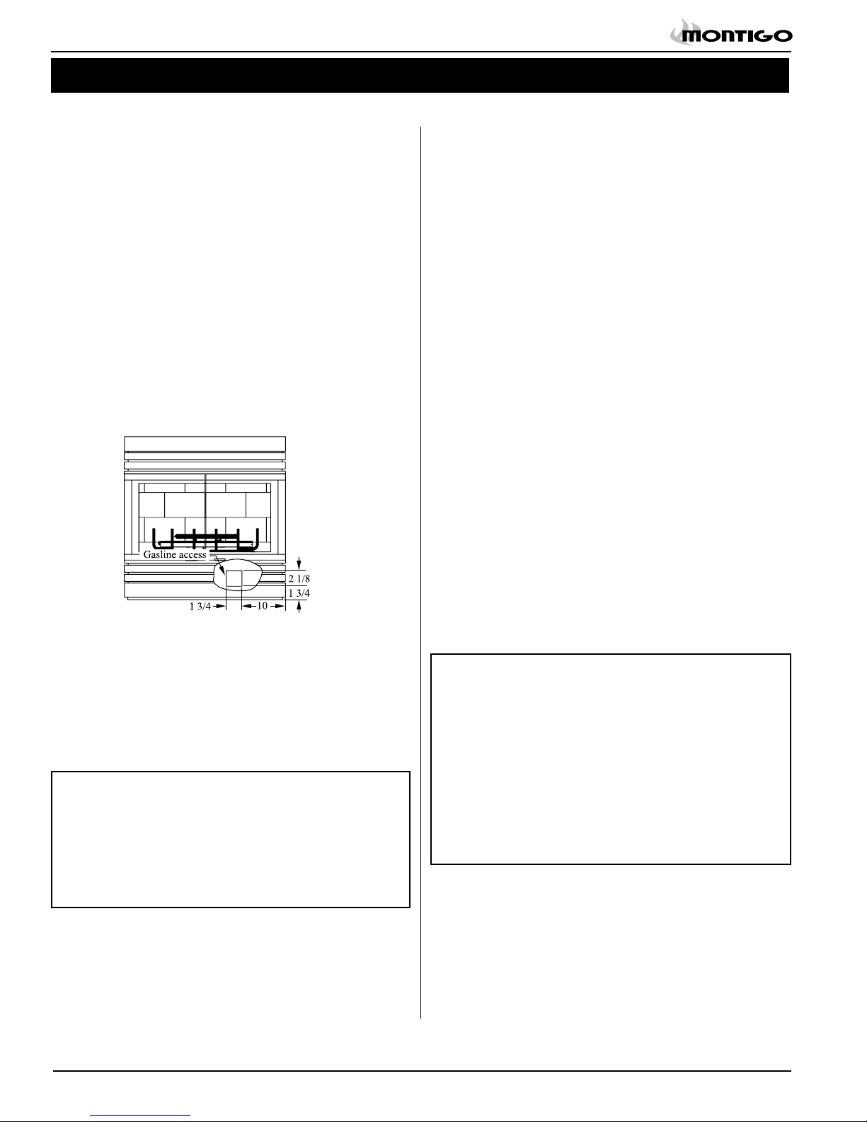
Installing The Gas Line
The gas line must be installed before finishing the M38DV-PRC fireplace. Natural Gas requires a minimum inlet gas supply pressure of
5.5" W.C. & a manifold pressure of 3.5" W.C. Propane Gas requires a
minimum inlet gas supply pressure of 11" W.C. & a manifold pressure
of 10" W.C. Provision must also be made for a 1/8" N.P.T. plugged
tapping and be accessible for test gauge connection immediately
upstream of the gas supply controls to the appliance. The fireplace
gas connection and the main operating gas valve is located behind
the removable brass trim at the bottom of the unit and need only be
attached to the gas line with an approved fitting, as required by the
applicable installation codes.
• Only use gas shut-off valves approved for use by the state, province,
region, or governing body, in which the appliance is being installed, or
as required by the applicable installation codes.
• Flexible gas connectors must not exceed 3 feet in length, unless it is
allowable within applicable installation codes.
The appliance and its individual shutoff valve must be disconnected
Vent Installation
This section covers the installation of direct venting and terminations.
For a detailed diagram of allowed termination locations, see Appen-
dix A.
Installation Requirements
The M38DV-PRC fireplace uses Premium venting components
with:
5" inner dia. /8" outer dia.
Minimum 2" clearance to combustibles required for vent pipes
Use only certified Montigo vent components. (Use of other parts
will void the Montigo warranty, and may impede the operation of
the fireplace.)
All joints must be secured with a minimum of two screws per joint
Vent terminations must not be recessed in walls or siding
Horizontal runs must be supported by a minimum of two supports
per horizontal run. A minimum of one screw on each side of support is also required
Flex vent sections may be stretched up to 50% of their total length
(eg. a 24" section may be stretched to 36")
Maximum horizontal run for a flex section with no vertical rise is 3
feet.
Flex vent sections over 3 feet must fall within the limits set by the
venting graph and must have a minimum vertical rise of 3 inches
per foot of flex.
Venting components can be used in any combination of solid/rigid
Figure 4. Gas line access.
from the gas supply piping system during any pressure testing of that
system at test pressures in excess of 1/2 psig (3.5 kPa).
The appliance must be isolated from the gas supply piping system by
closing its individual manual shutoff valve during any pressure testing
of the gas supply piping system at test pressures equal to or less than
1/2 psig (3.5 kPa).
* After gas line is connected each appliance connection,
valve and valve train must be checked while under normal
operating pressure with either a liquid solution, or leak detec
tion device, to locate any source of leak. Tighten any areas
where bubbling appears or leak is detected until bubbling
stops completely or leak is no longer detected.
a ame of any kind to test for leaks.
Do NOT use
-
Installing The Remote Switch
The M38DV-PRC is equipped with a remote-operated valve for use
with a wall switch. See Figure 19 for information on wiring the switch.
The valve is pre-wired and generates its own power. DO NOT con-
nect any external power to it.
Note: The switch location must not exceed 30' from the fireplace.
Solid vent sections may be cut less than half way from the tapered
end
Venting components can be used in any combination of solid/rigid
CAUTIONS:
• Vent terminations can be very hot. National Standards
require that all terminations accessible to the public (below
7 feet from grade level, on balconies, or decks) be installed
with a certified Montigo Heat Guard. (Part no. PTKOG)
• Do not obstruct, or attempt to conceal, the vent termination.
These actions will affect the operation of the fireplace, and
may be hazardous.
• In heavy snow areas, take extra care to prevent snow
buildup from obstructing the vent termination.
Page 4
XG0204 04/05
Installation
12
12
1212
12
11
11
Panorama Direct Vented Fireplace
Vent Terminations
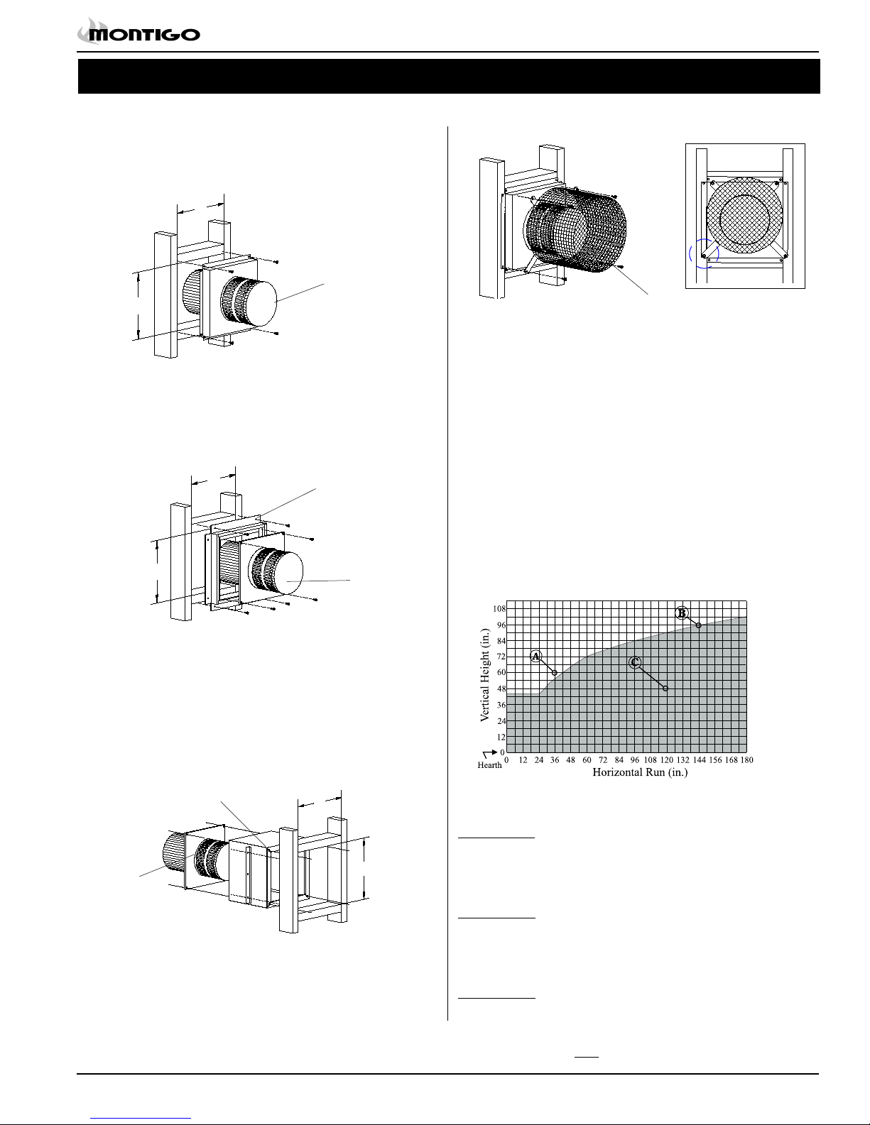
Installing Terminations with Built-In Frames
1. Frame the termination opening to 11" x 11".
2. Fasten the termination to the studs using a minimum of 4
PTO-3F
Figure 5a. Installing a PTO-3F termination.
Installing Terminations with MSR Frames
1. Frame the termination opening to 12" x 12".
2. Fasten the MSR frame to the exterior side of the studs using at
least 4 screws. Attach the termination to the MSR using a minimum of 4 screws.
MSR
PTO-3
2. Attach to the faceplate of the termination using four sheet metal
screws.
PTKOG
Figure 5d. Installing the heat guard.
Venting Runs
If your installation requires more than 12" of horizontal venting, some
vertical lift is required. Use the vent graph below to determine an
acceptable vent run. Unacceptable venting can affect the fireplace's
combustion.
the maximum horizontal vent run is 16 feet
The Venting Graph
Measure the vertical height from the fireplace hearth to the centre of
the termination and the horizontal run from the from the fireplace flue
collar to the wall flange of the termination. Plot on the Venting Graph
(Fig. 6) with an 'X'.
If the 'X' falls on or above the top boundary of the shaded area, the
installation is acceptable.
Figure 5b. Installing a PTO-3 termination with the MSR frame.
Installing Terminations with MOSR Frames
1. Frame the termination opening to 12" x 12".
2. Fasten the MOSR frame to the interior side of the studs using a
minimum of 4 screws.
3. Insert the termination into the MOSR frame as shown here, and
attach by screwing through the four pilot holes in the termination.
MOSR
Figure 6. Venting Graph.
Example A: (Acceptable Installation)
If the vertical dimension from the hearth is 60", and the horizon-
PTO-3
Figure 5c. Installing a PTO-3 termination with the MOSR frame.
Installing Heat Guards over Terminations
1. Ensure that the two long mounting brackets are facing the bot-
tom of the termination. (See inset). This will provide more heat
protection at the top of the termination, where temperatures are
highest.
XG0204 04/05
tal run to the wall flange of the vent termination is 36", this would
be an acceptable installation.
Example B: (Acceptable Installation)
If the vertical dimension from the hearth is 96" and the horizontal
run to the wall flange of the vent termination is 144", this would
be an acceptable installation.
Example C: (Unacceptable Installation)
If the vertical dimension from the floor of the fireplace is 48" and
the horizontal run to the wall flange of the vent termination is
120", this would NOT be an acceptable installation.
Page 5
Panorama Direct Vented Fireplace
Installation
Horizontal Vent Installation
Vent systems that terminate through a wall may comprise up to six
different components:
A - Termination PTO-3 (3" length)
PTO-3F (3" length)
B - Stucco Kits MSR (stucco frame)
MOSR (stucco can)
BSR (brick can)
C - Flex sections PFL-1 (12" section)
PFL-2 (24" section)
PFL-3 (36" section)
PFL-4 (48" section)
D - Solid sections PEXT-1 (12" section)
PEXT-2 (24" section)
PEXT-3 (36" section)
PEXT-4 (48" section)
E - Extensions PXT-5 (5" section)
PXT-10 (10" section)
F - 90° elbow PEL-90F/F
PEL-90M/M
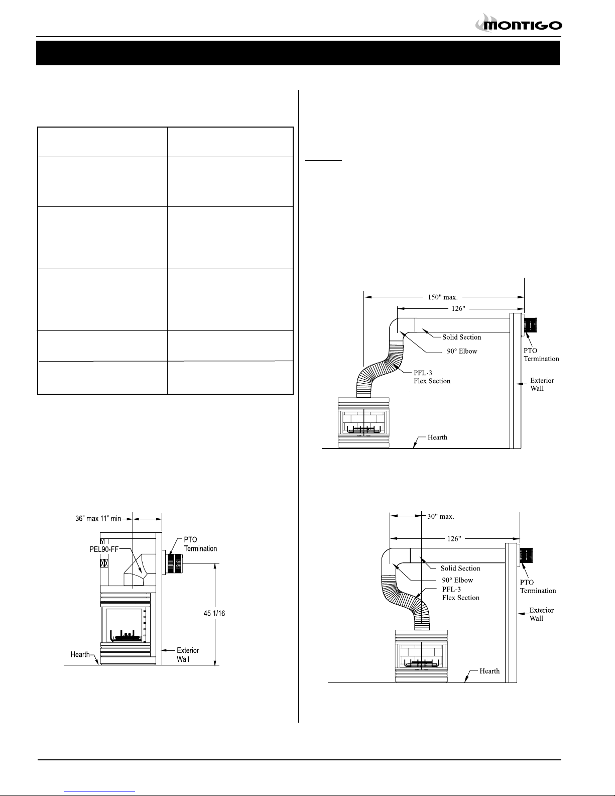
Long Vent Runs:
For longer or more complex vent runs, vertical lift is required. First
ensure that the planned run is acceptable using the Vent Graph. Plan
out the required components using the chart above. You may be able
to use fewer components using the chart below.
Example:
A rigid section and an elbow used in conjunction with 3 ft. flex section
(PFL-3) will, when extended in a chase, allow for a maximum horizontal run of twelve and one-half feet from the centre of the fireplace to
outside wall and a minimum of 7'6" when retracted in opposite direction. (See Figure 8 and 9.)
"C" flex sections and "D" solid sections may be used in conjunction
with one another to obtain different possible horizontal length installations. NOTE: Flex section must not exceed maximum horizontal
length of 3 feet.
Short Configurations:
For installations straight through the wall, use a 2" or 5" termination
(see above chart for Part #), and PXT-5 or PXT-10 to achieve the
desired length. The maximum horizontal vent run with no vertical lift
is 12".
See Figure 7.
Figure 7. Short Horizontal installation with PEL90-FF elbow.
Figure 8. Extended installation.
Figure 9. Retracted installation.
Page 6
XG0204 04/05
Installation
Panorama Direct Vented Fireplace
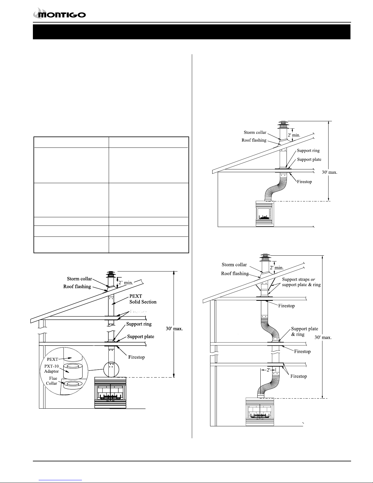
Vertical Vent Installations
Vertical Terminations must be installed:
• minimum 2' (two feet) above the highest point where
vent passes through the roof.
• minimum 6' (six feet) from a mechanical air inlet
• minimum 18" (1 1/2 feet) from a parapet wall.
Maximum vent height is 30 feet above fireplace.
Note: Flame characteristics will change if the maximum vent
height is used.
Minimum clearances 2" from vent to all combustible materials
must be maintained.
A - Termination PVTK-1
B - Flex sections PFL-1 (12" section)
PFL-2 (24" section)
PFL-3 (36" section)
PFL-4 (48" section)
C - Solid sections PEXT-1 (12" section)
PEXT-2 (24" section)
PEXT-3 (36" section)
PEXT-4 (48" section)
D - Support Ring & Plate PSPXT-7 (8" dia.)
E - Firestop PS-8 (8" dia.)
F - Roof Flashing PRF-7 (1/12 - 7/12 pitch)
PRF-12 (7/12 - 12/12 pt.)
A maximum of two offsets (each offset has two 90° bends) may
be made if the length of the offsets does not exceed 25% of the
vertical vent height, when measured center to center of piping.
Example: Typical vent installation.
30' vertical vent
2 - 2' offsets required
25% of 30' = 7-1/2' max. offset allowed
This venting configuration meets requirements.
Figure 11. Vertical venting with 1 offset Vertical venting with 1 offset
(1 offset= two 90° bends).
Figure 10. Straight, vertical venting. Using the required PXT-10 adap-
tor.
XG0204 04/05
Figure 12. Vertical venting using 2 offsets (1 offset= two 90° bends).
Page 7
 Loading...