

Montigo L-Series User Manual
For Use with L-Series or P-Series
April-01-15 8:18:44 AM
L38-DF/ST
L42-DF/ST
L52-DF/ST
P38-DF
P42-DF
P52-DF
Installing the L-Series and P-Series Fireplace Surround
1
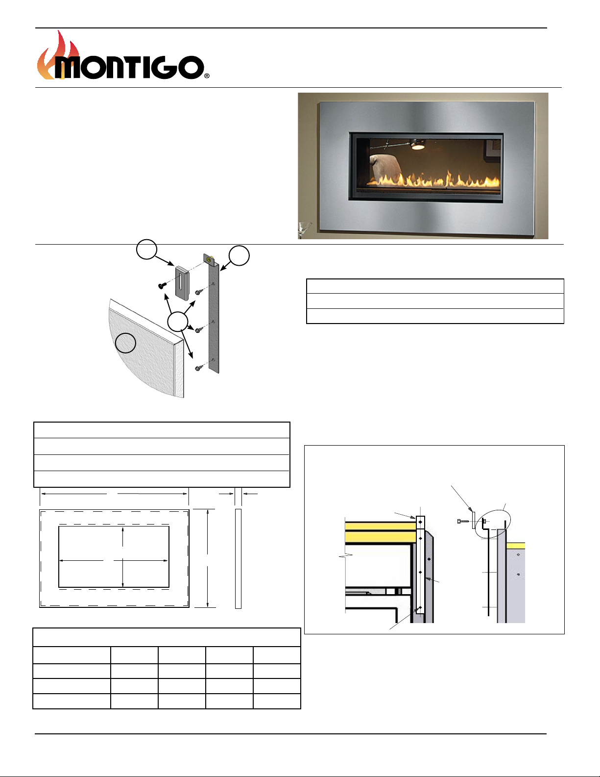
Parts Included
1) 1-Pc, Surround
2) 2-Pcs, Attachment Brackets
3) 4-Pcs, Moving Brackets
4) 1-Pkg. Hardware
O
3
2
Tools Required
1) Power Drill, (eight 1/8" holes)
2) #8 Hexhead Driver, (to match hardware)
4
3) Carpenters level (Final Step, if required)
Installing the Surround
To install the Montigo Stainless steel or Black contemporary
surround onto the L-Series or P-Series unit, follow these steps.
Step 1. Mark the location of the holes needed.
From the package of hardware locate one of the Attachment Brackets.
Hold this part in place as shown in Figure 2. With a pencil or pen mark
the (6) six holes on the face of the replace frame, (see Figure 2.) Note:
Ensure the brackets align with Figure 2. Below.
Moving Brackets (2)
1”
Align (2) attachment brackets
on center of frame verticals
(Left and Right side Typical)
(Left and Right side Typical)
Brackets to be
flush with top of
fireplace frame,
(Typical)
N
M
Surround Dimensions (in inches)
P
Model M N O P
P38DF/L38 DF/ST 35 5/16" 19 7/16" 49 13/16" 34 1/16"
P42DF/L42 DF/ST 39 5/8" 20 5/16" 54 1/8" 34 15/16"
P52DF/L52 DF/ST 47 3/16" 21 13/16" 65 3/16" 40 3/8"
Figure 1. Surround Dimensions (tolerance within 1/16")
Bracket to be
Flush with
outside edge
Mounting Holes (3) per side.
(Left and Right side Typical)
of fireplace,
(Typical)
Figure 2. Bracket Alignment
Step 2. Drill holes.
Before you go any farther now is the time to double check the location
of the holes, do they agree with Figure 2. If you are satised with the
location of the holes, use a punch to mark the holes, then using a 1/8"
drill, drill out the six holes.
XG0905 - 150204.1

Step 3. Install the (2) two Attachment Brackets. (See Figure 2)
FLUSH WITH
VALVE/BOTTOM
PANEL
March-31-15 12:54:25 PM
March-31-15 12:54:25 PM
April-01-15 8:18:44 AM
Install the two (2) Attachment Brackets you used as a guide. Have
someone hold one of the Brackets in place, using the Hex-tool, place a
self-tapping #8-18 sheet metal hex screw into the hole and twist it into
the hole half way
.
Follow this procedure for the remaining two (2) screws in the rst
bracket. After the three (3) screws are in place tighten them in place.
Repeat the procedure in Step 3 for the second Attachment Bracket.
Step 4. Install the (2) two Movable Brackets. (If installed disregard this
step. If not See Figure 3)
Install the two (2) Movable Brackets. (These move up or down to level
and align the surround. This will produce a symmetrical reveal when
correctly adjusted).
Moveable Bracket
10-24 Machine Screw
Cut out
Figure 3. Installing the Movable Brackets
Pick up one of the brackets, using the supplied hardware, mount it into
place. Slide the bolt through the bracket 'front to back', (See Figure 3),
then tighten the bolt using a open end wrench or socket.
Follow this procedure for the remaining bolt in the second Movable
Bracket.
Step 5. Installing the Lower Moveable Brackets
Using the self drilling screws supplied secure the moveable brackets to
the front of the replaces lower facia. The cut out on the moveable braket
should be such that the cut out is facing up. The moveable bracket
should be level with the top of the replace lower facia and spaced
evenly from left to right as to support the weight of the surround. See
gure 4 and 5.
Cut Out
Lower Facia
Moveable Bracket
Figure 5. Installing the Movable Brackets on Lower Facia
Step 6. Placing the Surround
Finally it's time to install the Stainless steel or Black Surround. For
this step it would be helpful to have someone help you hold the surround in place.
Lift the surround over the four (4) Movable Brackets and slide the
surround downward. The surround should securely lock in place in
the cut out in the lower moveable brackets. Center the surround left
to right.If the surround doesn't clear the top or bottom of the replace
you will have to adjust the movable brackets up or down. Remove
the surround place it aside. Adjust the bracket as required. Repeat as
necessary.
Step 7. Final adjusting of the Surround
This step is not necessary if the surround ts tightly around the
replace, or the adjustment is acceptable. But, if your surround has
an uneven reveal, or unequal gap around/between the replace and
surround, using a carpenters level adjust the Movable brackets as
needed.
Finally place the adjusted Surround back on the Brackets and admire
your Contemporary Montigo replace.
Moveable Bracket
Lower Facia
Figure 4. Installing the Movable Brackets on Lower Facia
XG0905 - 150204.1
WARNING
When installing the replace - gas lines, ttings,
accessories or any other objects cannot impede the
proper movement of the door buckles.
WARNING
Screen Barrier must still be used with the Surround.
The screen should only ever be removed for servicing and then reinstalled before operating replace.
 Loading...