

Montigo IOSK4 User Manual
Indoor / Outdoor Sealing Kit For R420 ST
Thursday, June 09, 2011 2:52:22 PM
Use this instruction in conjuction with unit
instruction manual (Doc. XG0772)
Follow the instructions for the unit installation in the up to Step 1 on
Page 7 of the installation guide.
The unit is in place with the screws removed as illustrated there.
Installation Instruction
Kit Part No. IOSK4
IOSK4-A01
IOSK4-A02
IOSK4-A03
420-551
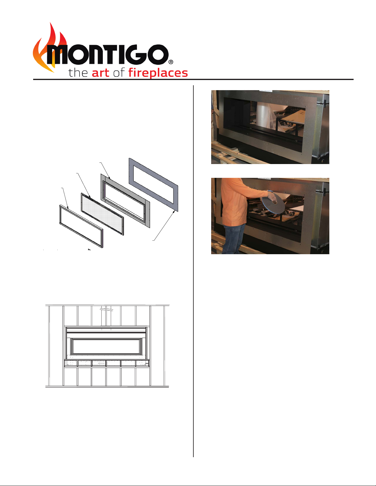
Figure 1: Indoor/ Outdoor Sealing Kit Ccmponents
STEP 1: Back frame the unit with the metal header supplied by Montigo
above the unit and either combustible or non-combustible framing to the
sides and bottom maintaining clearances as shown and ensuring the
gallvanized apron (Fig 1, Part No. 420-551) can be attached to the framing.
Figure 3: Attach galvanized apron to unit
Figure 4: Install silicone gasket
STEP 4: Attach the stainless steel frame (Fig. 1, Part No. IOSK4-A01)
to the galvanized frame lining up the holes around perimeter. Secure in
place through holes across the top and down the sides. Do not secure
the bottom ange.
STEP 5: Apply approved waterproong membrane over the ange of
the frame on the top and sides and under the ange of the frame at
the bottom. The membrane should overlap the frame approximately 2"
around the perimeter.
Figure 2: Backframe unit
CLEARANCE TO COMBUSTIBLES:
6" Top, 3" each side, 3" bottom from the protruding window box.
STEP 2: Place the galvanized apron and attach to the unit using the 6
screws removed from the unit face, Figure 3.
STEP 3: Install the silicon gasket material (supplied by Montigo) in one
continuous strip with the joint at the bottom, Figure 4.
STEP 6: All facing materials may now be installed over the frame.
BE CERTAIN TO MAINTAIN 6" ABOVE AND 3" ON SIDES AND BOTTOM
TO ANY COMBUSTIBLE MATERIAL
STEP 7: Mount the framed glass (Fig 1, IOSK4-A02) onto the unit and
secure in place rst with only the two side screws.
STEP 8: Place the Galvanized strips (4 supplied) at each corner lining up
screw holes and secure both the strips and the framed glass to the unit.
STEP 9: Attach the stainless steel trim (Fig1, IOSK4-A03), by placing it
on and ensuring the magnets catch the previously placed galvanized strip.
IOSK 420 Instructions Cont'd
IOSK4-A03
IOSK4-A02
IOSK4-A01
ISOMETRIC VIEW
(NTS)
PART NUMBER
DESCRIPTION
QTY. REV.
1
IOSK4-A03
DOOR TRIM ASSEMBLY, IOSK4
1
A
2
420-551
BACK PLATE, IOSK4
1
A
3
IOSK4-A01
OUTER FRAME, IOSK4
1
A
4
IOSK4-A02
DOOR ASSEMBLY, IOSK4
1
A
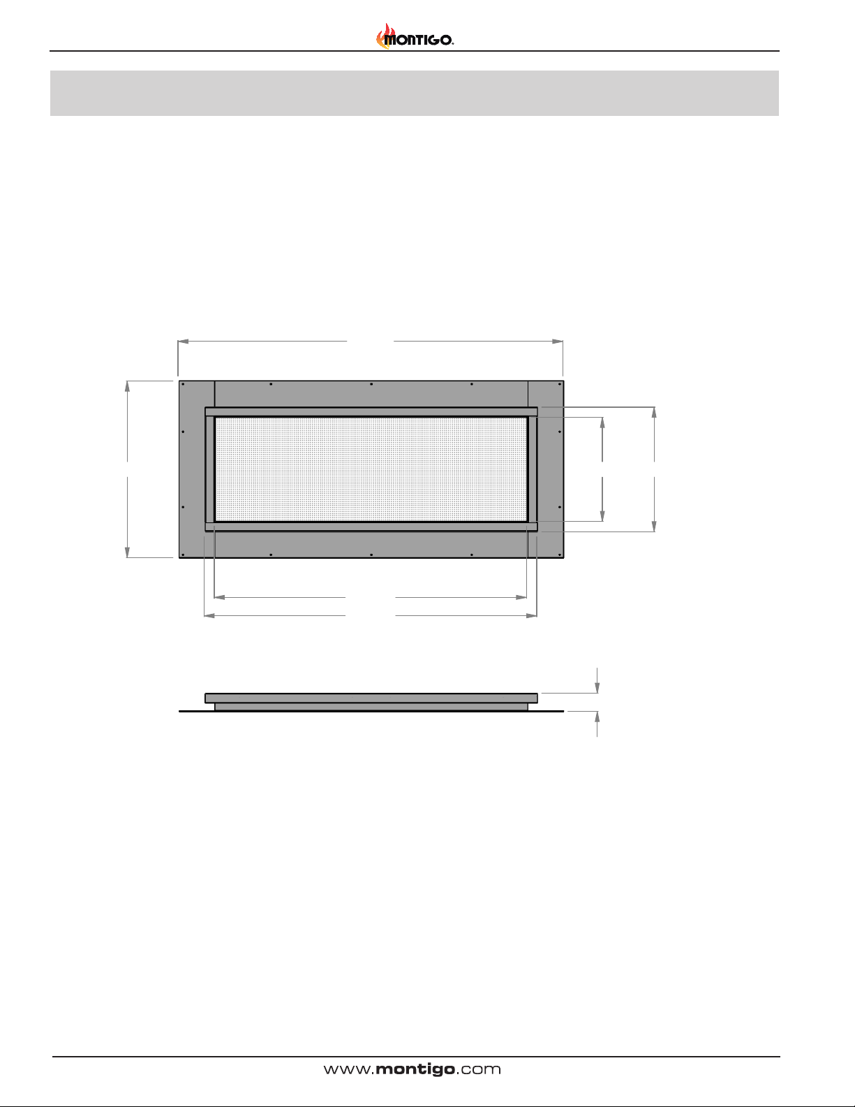
61.25
28.12
49.693
52.938
16.558 19.803
2.901
 Loading...