

Montigo MD34-DV-2, Homefire plus MD34-DV-2, Homefire plus MD34DT-2, Homefire plus MD34DR-2, Homefire plus MD34DT-I-2 Operation Manual
...
Installation
Questions? Email us at fireplaces@montigo.com or visit our website at www.montigo.com.
Operation &
Maintenance
MD34-DV-2
Homefire
Warning:
Improper installation, adjustment,
alteration, service or maintenance can cause
injury or property damage. Refer to this
manual. For assistance or additional
information consult a qualified installer,
service agency or the gas supplier.
For Your Safety:
Do not store or use gasoline
or other flammable vapors
and liquids in the vicinity of
this or any other appliance.
What To Do If You Smell Gas:
Do not try to light any appliance.
Do not touch any electrical switch; do not use any phone in your building.
Immediately call your gas supplier from a neighbor's phone. Follow the gas
supplier's instructions.
If you cannot reach your gas supplier, call the fire department.
Modular
Gas Fireplace
n Check local codes and
read all instructions
prior to installation.
n Leave this manual with
the owner.
MD34-DV-2 Homefire
Table Of Contents
Introduction ............................................................................ 2
Installation
Installing the Fireplace Shell ........................................ 3
Installing the Gasline .................................................... 4
The Remote Switch ......................................................4
Direct Vent Installation .................................................. 4
General Requirements ....................................4
Terminations.................................................... 5
Top Vent Through-the-Wall Installations ......... 6
Top Vent Through-the-Roof Installations ........ 8
Rear Vent Through-the-Wall Installations ....... 9
Rear Vent Multi-Elbow Installations ...............10
Construction around the fireplace
Facing ............................................................11
Mantels and Surrounds................................. 11
Wiring ............................................................... 11 - 12
Installing the Logset.................................................... 12
Removing and Installing the Insert ............................13
Removing and Installing the Door .............................13
Operation...................................................................... 14 - 16
Maintenance................................................................. 16 - 17
Warranty................................................................................18
Appendix
A. Termination Locations ...........................................19
CAUTIONS
Due to its high operating temperatures, the appliance
should be located out of traffic & away from furniture and
draperies.
n Children and adults should be alerted to the hazards
of the high surface temperature, which could cause
burns or clothing ignition.
n Young children should be carefully supervised when
they are in the same room as the appliance.
n Clothing or other flammable materials should not be
placed on or near the appliance.
Introduction
About Modular Fireplaces and the Homefire Plus:
The MD34-DV-2 Homefire Plus includes a 25,000 BTU dual burner
and embers. All 34 Series Modular Fireplaces allow quick and
easy upgrades in the future. The MD34-DV-2 can be upgraded to a
Wildfire Burner. Contact your dealer for more information. The
MD34-DV-2 model is available in four versions:
nTop Vent (Product Code MD34DT-2)
nRear Vent (Product Code MD34DR-2)
nElectronic Ignition - Top Vent (Product Code MD34DT-I-2)
nElectronic Ignition - Rear Vent (Product Code MD34DR-I-2)
The MD34-DV-2 is certified as a Vented Gas Fireplace Heater (ANSI
Z21.88-2000 · CSA 2.33-2000) and is rated for:
Natural Gas 24,500 BTU/H (7.2 Kilowatts) Maximum Input
19,500 BTU/H (5.7 Kilowatts) Minimum Input
Propane 23,000 BTU/H (6.7 Kilowatts) Maximum Input
17,700 BTU/H (5.2 Kilowatts) Minimum Input
How to use this manual:
This manual covers all models and unless otherwise specified, the
designation MD34-DV-2 refers to all models. Sections which are specific
to a particular model are marked with a symbol, plus the
appropriate model number.
Warranty and Installation Information:
The Montigo warranty will be voided by, and Montigo disclaims any
responsibility for, the following actions:
n Modification of the fireplace and/or components including Direct-Vent
assembly or glass doors.
n Use of any component part not manufactured or approved by
Montigo in combination with this Montigo fireplace system.
n Installation other than as instructed in this manual.
Consult your local Gas Inspection Branch on installation requirements for factory-built gas fireplaces. Installation & repairs should
be done by a qualified contractor.
Installations in Canada must conform to the current CAN/CGA
B-149.1 and .2 Gas Installation Code and local regulations. If the
optional air-circulating fan kit is installed, it must be electrically
grounded in accordance with CSA C22.1 Canadian Electrical Code
Part 1 and/or Local Codes.
Installations in the USA must conform to local codes, or in the
absense of local codes to the National Fuel Gas Code, ANSI
Z223.1-1988. If the optional air-circulating fan is installed, it must
be grounded in accordance with local codes or, in the absence of
local codes, with the National Electrical Code, ANSI/NFPA 70-
1987.
Page 2
Part No. XG0106B
Installation
Installing The Fireplace Shell
The fireplace may be installed in any location that maintains proper
clearances to air conditioning ducts, electrical wiring and plumbing.
Safety, as well as efficiency of operation, must be considered when
selecting the fireplace location. Try to select a location that does not
interfere with room traffic, has adequate ventilation, and offers an
accessible pathway for Direct Vent installation. Refer to page 4 - Vent
Installation for more information.
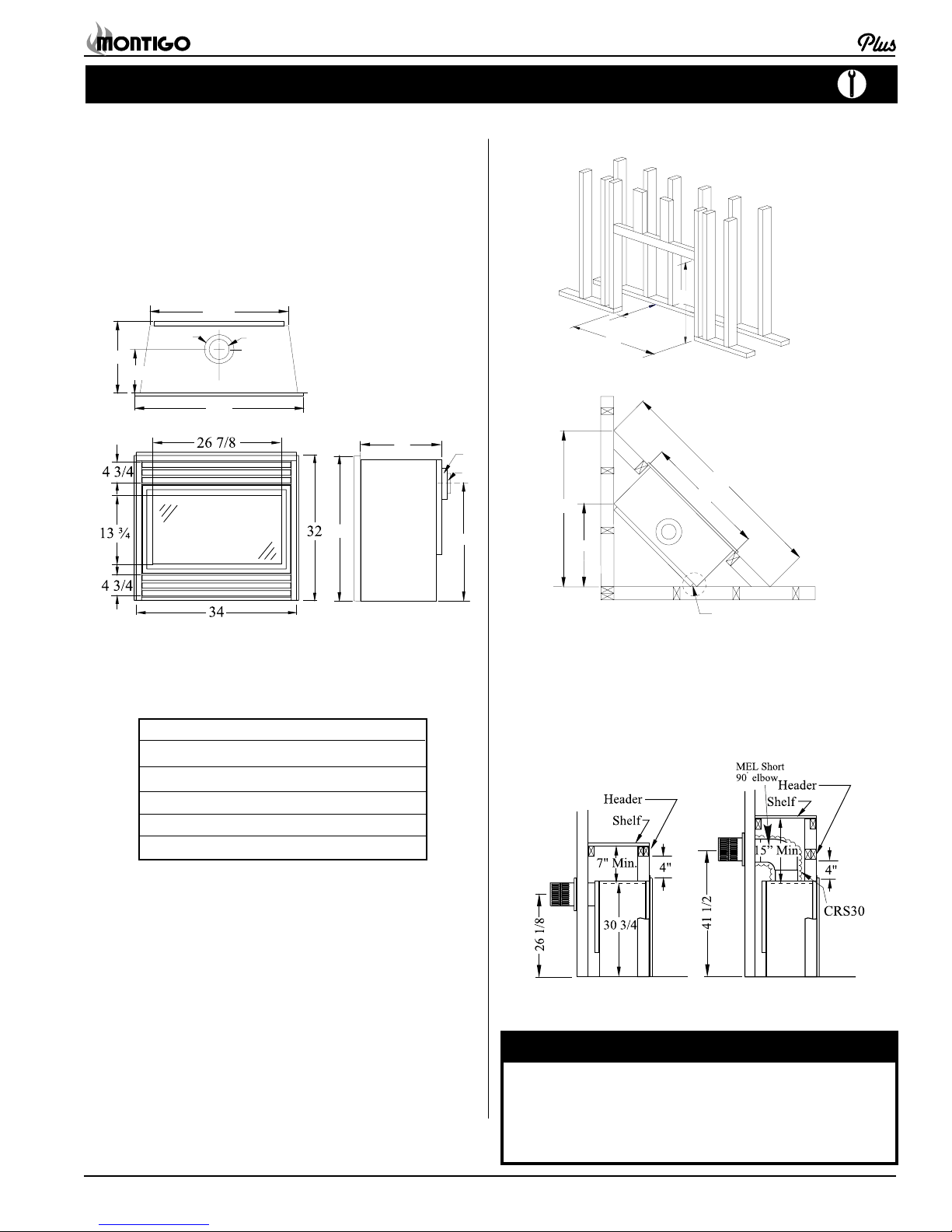
The fireplace dimensions are shown below:
15
8 3/4
31 1/2
Ø7
Top Vent
Ø4
C
34
15
32
Ø7
Ø4
26 1/8
Framing
15 3/4
33
Figure 2. Framing dimensions.
42
22 1/4
MD34-DV-2 Homefire
* When sheetrock is
not used behind the
fireplace, framing
36
59 3/8
33
depth may be
reduced to 15"
Front View
Rear Vent
Figure 1. Fireplace dimensions.
Clearances
The MD34-DV-2 clearances to combustible materials are:
Top - Rear Vent* 7"
Top - Top Vent*** 35"
Back 0"
Side 1"
Floor 0"
Mantle** 10"
* Clearance from the top of the fireplace to a combustible
ceiling within the fireplace enclosure.
** Refer to page 11.
*** If the standard elbow (MEL90) is used with the Low
Clearance Sleeve (CRS30) the Top Clearance is 15".
If the Low Clearance Sleeve (CRS30) is NOT used
over the elbow, the Top Clearance is 35".
Unprotected combustible walls which are perpendicular to the
fireplace opening, must not project beyond the shaded area shown
in Figure 19b.
For protection against freezing temperatures, it is recommended
that outer walls of the chase be insulated with a vapour barrier. This
will reduce the possibility of a cold-air convection current on the
fireplace.
0" clearance
to corners only
Figure 3. Corner framing dimensions.
When installing a shelf over the top of the fireplace, the following
guidelines must be adhered to: For Rear Vent models (MD34DR-2),
the minimum clearance from the top of the fireplace to a shelf is 7". For
Top Vent models (MD34DT-2), the minimum clearance when using the
CRS30 is 15". (Minimum 1" clearance must still be maintained around
the vent pipes.)
Rear Vent
Top Vent
Figure 4. Framing for shelves over the fireplace.
WARNING:
When this appliance is installed directly on carpeting, tile or any
combustible material other than wood flooring, it must be
installed on a metal or wood panel extending the full width and
depth of the appliance.
Part No. XG0106B
Page 3
MD34-DV-2 Homefire
Installation
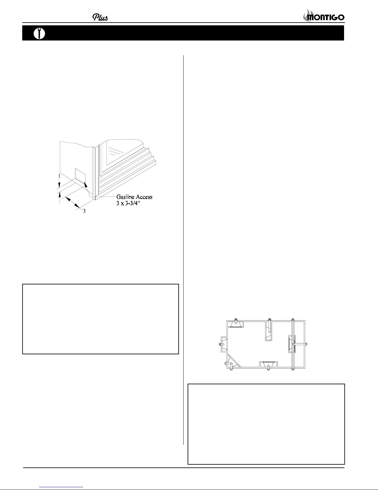
Installing The Gas Line
The gas line must be installed before finishing the MD34-DV-2 Fireplace.
Natural Gas requires a minimum inlet gas supply pressure of 5.5"
W.C. & a manifold pressure of 3.5" W.C. Propane Gas requires a
minimum inlet gas supply pressure of 11" W.C. & a manifold pressure of
10" W.C. Provision must also be made for a 1/8" N.P.T. plugged tapping
and be accessible for test gauge connection immediately upstream of the
gas supply controls to the appliance. The fireplace gas connection and
the main operating gas valve is located behind the removable brass trim
at the bottom of the unit and need only be attached to the gas line with an
approved fitting, as required by the applicable installation codes.
Figure 5. Gas line access.
During any pressure testing of the gas supply piping that excedes 1/ 2
psig (3.5 kPa), the appliance and its individual shutoff valve must be
disconnected from gas supply system.
When pressure testing the gas supply piping system at test pressures of
less than or equal to 1/2 psig (3.5 kPa), the appliance must be isolated
from the gas supply piping system by closing its individual manual shutoff
valve.
Note: After gas line is connected, each appliance connection,
valve and valve train must be checked while under
normal operating pressure with either a liquid solution, or
leak detection device, to locate any source of leak. Tighten
any areas where bubbling appears or leak is detected until
bubbling stops completely or leak is no longer detected.
DO NOT use a flame of any kind to test for leaks.
Vent Installation
This section covers the installation of direct venting and terminations.
Installation Requirements
n MD34-DV-2 fireplaces are certified for use with Montigo Standard
Series (4" / 7") venting components
n Minimum 1" clearance to combustibles required for vent pipes
n Use only certified Montigo vent components. (Use of other
parts will void the Montigo warranty, and may impede the
operation of the fireplace.)
n All joints must be secured with a minimum of two screws per joint
n Vent terminations must not be recessed in walls or siding
n Horizontal runs must be supported by a minimum of two supports
per horizontal run. A minimusm of one screw on each side of
support is also required
n Flex vent sections may be stretched up to 50% of their total length
(eg. a 24" section may be stretched to 36")
n Maximum horizontal run for a flex section with no vertical rise is 3 feet.
n Flex vent sections over 3 feet must fall within the limits set by the
venting graph and must have a minimum vertical rise of 3 inches
per foot of flex.
n Solid vent sections may be cut less than half way from the tapered end
n Venting components can be used in any combination of solid/rigid
pipe or flex pipe and in any orientation (Male connectors can face
in any direction)
Vent Terminations
Selecting A Termination Location
Choosing your vent termination location will help to determine whether
you need to use a top vent or rear vent fireplace. Figure 6, below,
shows typical fireplace locations and the venting options they provide.
For a more detailed diagram of allowed termination locations, see
Appendix B.
Installing The Remote Switch
The MD34-DV-2's gas valve, located behind the lower brass trim, may
be connected to a wall switch. The valve generates its own power. This
is a millivolt circuit. Use only low voltage wire, and DO NOT connect any
external power to it.
Refer to Figure 28 for wiring requirements.
Note: The switch location must not exceed 30' from the fireplace.
Page 4
Figure 6. Fireplace locations and vent terminations.
Cautions:Cautions:
Cautions:
Cautions:Cautions:
n Vent terminations can be very hot. If the termination is less
than 7 feet above a public walkway, it should be fitted with a
certified Montigo Heat Guard. (Part no. MTKOG)
n Do not obstruct, or attempt to conceal, the vent termination.
These actions will affect the operation of the fireplace, and
may be hazardous.
n In heavy snow areas, take extra care to prevent snow buildup
from obstructing the vent termination.
Part No. XG0106B
Installation
MD34-DV-2 Homefire
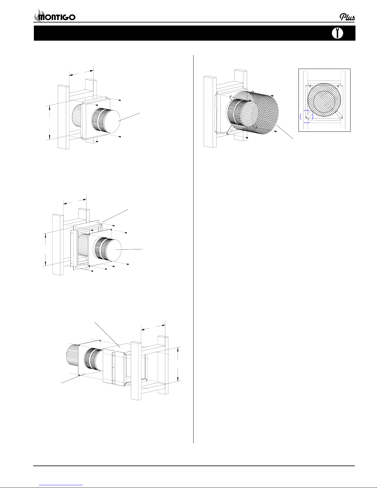
Installing Terminations with Built-In Frames
11
MTO-3F
11
1. Frame the termination opening to 11" x 11".
2. Fasten the termination to the studs using a minimum of 4
screws.
Installing Terminations with MSR Frames
12
MSR
Installing Heat Guards over Terminations
MTKOG
1. Ensure that the two long mounting brackets are facing the
bottom of the termination. (See inset). This will provide more
heat protection at the top of the termination, where temperatures are highest.
2. Attach to the faceplate of the termination using four sheet metal
screws.
12
1. Frame the termination opening to 12" x 12".
2. Fasten the termination to the studs using a minimum of 4
screws.
MTO-3
Installing Terminations with MOSR Frames
MOSR
MTO-3
1. Frame the termination opening to 12" x 12".
2. Fasten the MOSR frame to the interior side of the studs using
a minimum of 4 screws.
3. Insert the termination into the MOSR frame as shown here,
and attach by screwing through the four pilot holes in the
termination.
1212
12
Part No. XG0106B
Page 5
MD34-DV-2 Homefire
Installation
Top Vent Venting Runs
For the MD34-DV-2, there are two types of installations: A) ThroughThe-Wall Installations and B) Vertical (Through-The-Roof) Installations.
A) Through-The-Wall Installations
Before you install any venting, you must determine whether the venting
run will be acceptable. Unacceptable venting can affect the fireplace's
combustion.
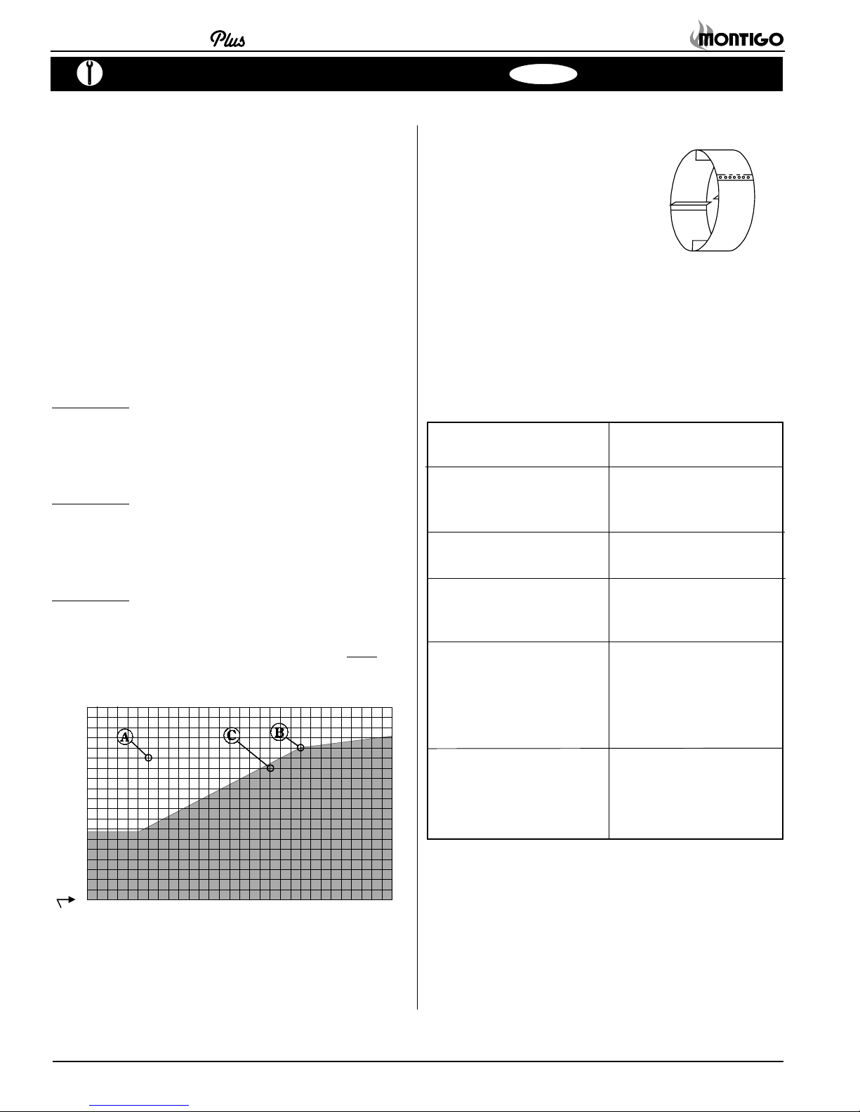
The Venting Graph
Measure the vertical height from the fireplace hearth to the centre of the
termination and the horizontal run from the from the fireplace flue collar to
the wall flange of the termination. Plot on the Venting Graph (Fig. 7) with
an 'X'.
If the 'X' falls on or above the top boundary of the shaded area, the
installation is acceptable.
Example A: (Acceptable Installation)
If the vertical dimension from the hearth is 84" and
the horizontal run to the wall flange of the vent
termination is 36", this would be an acceptable
installation.
Example B: (Acceptable Installation)
If the vertical dimension from the hearth is 90" and
the horizontal run to the wall flange of the vent
termination is 126", this would be an acceptable
installation.
Example C: (Unacceptable Installation)
If the vertical dimension from the floor of the fireplace is 78" and the horizontal run to the wall flange
of the vent termination is 108", this would
an acceptable installation.
108
96
84
72
60
48
36
24
12
0
12 24 36 48 60 72 84 96 108 132120 144 156 168 180
0
Hearth
Horizontal Run (in.)
Figure 7. MD34-DV-2 Top Vent Venting Graph
NOT be
Top Vent
Heat Shields
Due to high flue temperatures, heat shields
are required on all 34 Series Modular
Direct Vent installations (except those with
vertical terminations) at the point where the
venting connects to the termination. With
the heat shield, vent clearances can be
maintained at 1".
Figure 8. Heat Shield. Install by sliding over the vent pipe where it
passes through combustible construction.
Available Top Vent Components
The following venting components are available for the MD34-DV-2
Top Vent:
A - Termination MTO-3 (3" length)
MTO-3F (3" length)
B - Stucco Kits MSR (stucco frame)
MOSR (stucco can)
BSR (brick can)
D - Flex sections MFL-1 (12" section)
MFL-18 (18" section)
MFL-2 (24" section)
MFL-3 (36" section)
MFL-4 (48" section)
E - Solid sections EXT-18 (18" f/f section)
MEXT-1 (12" m/f section)
MEXT-2 (24" m/f section)
MEXT-3 (36" m/f section)
MEXT-4 (48" m/f section)
F - Elbows
NOTES: All dimension lengths for vertical or horizontal runs
are measured from center of the vent pipe.
Venting runs must fall within the limits set by the
venting graph (see Figure 7).
MEL-90M (m/m 90° elbow)
MEL-90F (f/f 90° elbow)
MEL-90FM (f/m 90° elbow)
EEL-45 (f/m 45° elbow)
Page 6
Part No. XG0106B
 Loading...