

Montigo H52-DFN Operation Manual
Installation
®
C US
Operation &
Maintenance
H52-DFN
Gas Fireplace
Warning:
Improper installation, adjustment,
alteration, service or maintenance can
cause injury or property damage. Refer to
this manual. For assistance or additional
information consult a qualied installer,
service agency or the gas supplier.
For Your Safety:
Do not store or use gasoline
or other flammable vapors
and liquids in the vicinity
of this or any other
appliance.
Safety Notice:
Glass doors on gas fireplaces are
extremely hot while the fireplace is on
and remain hot even after the fireplace
has been turned off. Safety screens
are available and can reduce the risks
of severe burns. Please keep children
away from the fireplace at all times.
Check local codes and read all
instructions prior to installation.
Installer: Leave this manual
with the appliance.
Consumer: Leave this man-
ual for future reference.
What To Do If You Smell Gas:
• Do not try to light any appliance.
• Do not touch any electrical switch; do not use any phone in your building.
• Immediately call your gas supplier from a neighbor's phone. Follow the gas
supplier's instructions.
• If you cannot reach your gas supplier, call the re department.
H52-DF Gas Fireplace
Warning:
Read this manual before installing, operating or troubleshooting this
appliance. Please retain this owner's manual for future reference.
Congratulations
Congratulations on selecting a Montigo gas replace, an elagent and
well designed gas replace built to your specications. The Montigo
gas replace you have selected is designed to provide the utmost in
safety, reliability, and engineering standards.
As the owner of this new replace, you'll want to read and carefully
follow all the instructions contained in this Installation, Operations and
Maintenance manual. Pay special attention to all cautions, warnings,
and Important warnings.
This owner's manual should be retained for future reference. We
suggest that you keep it with all your other important documents and
product manuals.
The information contained in this owner's manual, unless noted otherwise, applies to all models, and gas control systems.
Your new Montigo gas replace will give you years of durable, reliable
use. Welcome to the FireFeature family of gas replace products.
Safety Alert Key:
• DANGER!
Indicates a hazardous situation which, if not avoided will result in death or serious injury.
• WARNING! Indicates a hazardous situation which, if not avoided could result in death or serious injury.
• CAUTION! Indicates a hazardous situation which, if not avoided, could result in minor or moderate injury.
• NOTICE: Used to address practices not related to personal injury.
• Important: Used to address practices not related to personal injury.
Table Of Contents
Congratulations
Safety Alert Key
Introduction ................................................................................. 3
Installation
Installing and Framing the Fireplace ..............................3
Installing the Gasline ...................................................... 4
Termination Installation ..................................................4
Installing Standoffs ......................................................... 5
The Remote Switch ........................................................ 5
Power Vent Installation..............................................5 - 9
Installing The Horizontal & Vertical Power Vent ........... 10
Construction around the fireplace
Facing .............................................................. 11
Mantels and Surrounds ............................ 11 - 12
Installation of the Logset .......................................12 - 13
Removing and Installing the Door .........................13 - 14
Operation ................................................................................. 15
Maintenance ........................................................................... 16
Warranty .................................................................................17
Appendix
A. Termination Locations .............................................. 18
B. State of Massachusetts. ..........................................19
Page 2
Part No. XG0650
Introduction
H52-DF Gas Fireplace
Thank You for choosing a Montigo Gas Fireplace.
About this Fireplace:
The H52-DFN is a replace with a pan-style burner and glowing embers.
This replace is ONLY available as a Top Vent, natural gas replace.
The H52-DFN is rated for Natural Gas at 60,000 BTU/H (17.65 Kilowatts)
Input. Available in Intermittent Pilot (HSI), NG Models Top Vent Only.
How to use this manual:
This manual covers installation, operation and maintenance. Lighting,
operation and care of this replace, and can be easily performed by
the homeowner. However, all installation and service work should be
performed by a qualied or licensed installer, plumber, or gas tter who
is qualied or licensed by the state, province, region, or governing body
in which the appliance is being installed.
Warranty and Installation Information:
The Montigo warranty will be voided by, and Montigo disclaims any
responsibility for, the following actions:
Modication of the replace and/or components including Direct-Vent ■
assembly or glass doors.
Use of any component part not manufactured or approved by Montigo in ■
combination with this Montigo replace system.
Installation other than as instructed in this manual. ■
Consult your local Gas Inspection Branch on installation requirements
for factory-built gas replaces. Installation & repairs should be done by
a qualied contractor.
Installations in Canada must conform to the current CAN/CGA B-
149.1 and .2 Gas Installation Code and local regulations. If the optional
air-circulating fan kit is installed, it must be electrically grounded in
accordance with CSA C22.1 Canadian Electrical Code Part 1 and/or
Local Codes.
Installations in the USA must conform to local codes, or in the absence
of local codes to the National Fuel Gas Code, ANSI Z223.1-1988. If the
optional air-circulating fan is installed, it must be grounded in accordance
with local codes or, in the absence of local codes, with the National
Electrical Code, ANSI/NFPA 70-1987. See Appendix B for installation
within the State of Massachusetts.
CAUTION!
Due to its high operating temperatures, the appliance
should be located out of traffic & away from furniture and
draperies.
Children and adults should be alerted to the hazards
of the high surface temperature, which could cause
burns or clothing ignition.
Young children should be carefully supervised when
they are in the same room as the appliance.
Clothing or other flammable materials should not be
placed on or near the appliance.
Important:
Natural Gas equipped models may be installed using
Top Vent applications ONLY.
Part No. XG0650
Page 3
H52-DF Gas Fireplace
Installation
Installing The Fireplace Shell
The replace may be installed in any location that maintains proper clearances to air conditioning ducts, electrical wiring and plumbing. Safety,
as well as efciency of operation, must be considered when selecting
the replace location. Try to select a location that does not interfere
with room trafc, has adequate ventilation, and offers an accessible
pathway for Direct Vent installation. Refer to page 4 - Vent Installation
for more information.
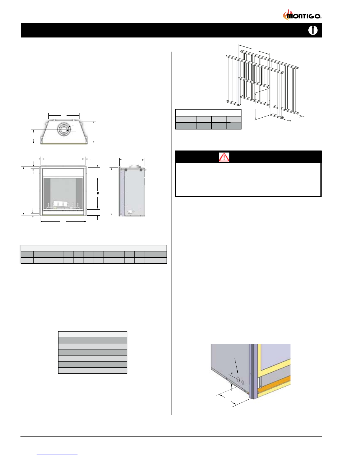
The replace dimensions are shown below:
H
K
J
I
C
L
K
C
L
Top View
D
D
B
F
C
A
Front View
Figure 1. Fireplace dimensions.
H52 Fireplace Dimensions
H52DF
A
52B56C47
D
1
2
37
/
2
Clearances
These clearances apply to all dimensions except the framed opening,
where the clearance to combustibles is 0". The H52DFN clearance to
unprotected combustible walls which are perpendicular to the replace
opening, must not project beyond the shaded area shown in Fig. 8.
For protection against freezing temperatures, it is recommended that
outer walls of the chase be insulated with a vapor barrier. This will reduce
the possibility of a cold-air convection current on the replace.
Clearance to Combustib
Top (Top Vent)
Sides
Floor
Back
Mantel
Unprotected combustible walls which are perpendicular to the replace
opening, must not project beyond the shaded area shown in Figure 8.
For protection against freezing temperatures, it is recommended that
outer walls of the chase be insulated with a vapor barrier. This will reduce
the possibility of a cold-air convection current on the replace.
G
J
D
12”
6 1/2”
4
GH
7
28
See graph, Page 9
EF
3
/
/
8
38
H52DFN
36”
2”
0”
2”
B
les
G
Side View
I8J
51
19
L
KR
N/A
N/A
Framing
N
M
Framing Dimensions
O
H52DF
N
M
1
52
56
/
4
O
3
1
29
4
/
/
4
Figure 2. Framing dimensions.
WARNING!
When this appliance is installed directly on carpeting, tile or any
combustible material other than wood ooring, it must be installed
on a metal or wood panel extending the full width and depth of
the appliance.
Installing The Gas Line
The gas line must be installed before nishing the H52-DFN Fireplace.
Natural Gas requires a minimum inlet gas supply pressure of 5.5" W.C.
& a manifold pressure of 3.5" W.C. Provision must also be made for a
1/8" N.P.T. plugged tapping and be accessible for test gauge connection
immediately upstream of the gas supply controls to the appliance. The
replace gas connection and the main operating gas valve is located
behind the removable trim at the bottom of the unit and need only be
attached to the gas line with an approved tting, as required by the
applicable installation codes.
To access the replace gas connection the main burner must be
removed as shown below in gure 3.
• Only use gas shut-off valves approved for use by the state, province,
region, or governing body, in which the appliance is being installed, or
as required by the applicable installation codes.
• Flexible gas connectors must not exceed 3 feet in length, unless it is
allowable within applicable installation codes.
Gasline Acces
0.875 dia.
2
7
to center
Figure 3. Gas line access.
Page 4
Part No. XG0650
2.5”
Installation
12
12
11
11
1212
12
H52-DF Gas Fireplace
Note: After gas line is connected, each appliance connection,
valve and valve train must be checked while under normal
operating pressure with either a liquid solution, or leak
detection device, to locate any source of leak. Tighten any
areas where bubbling appears or leak is detected until
bubbling stops completely or leak is no longer detected.
DO NOT use a flame of any kind to test for leaks.
Installing The Standoffs
To avoid elevated mantel temperatures, the H52-DFN gas
replace is required to have the supplied standoffs installed.
The replace is supplied with two standoffs. Bend and install these
standoffs on top of the replace ensuring that the height of the standoff
maintains a 2.5" clearance.
Figure 4. Installing the standoff's.
Installing The Remote Switch
The H52-DFN's gas valve, located behind the lower trim, may be
connected to a wall switch. The valve generates its own power on a
millivolt circuit. Use only low voltage wire, and DO NOT connect
any external power to it.
Refer to Figure 15 for wiring requirements.
Note: The switch location must not exceed 30' from the replace.
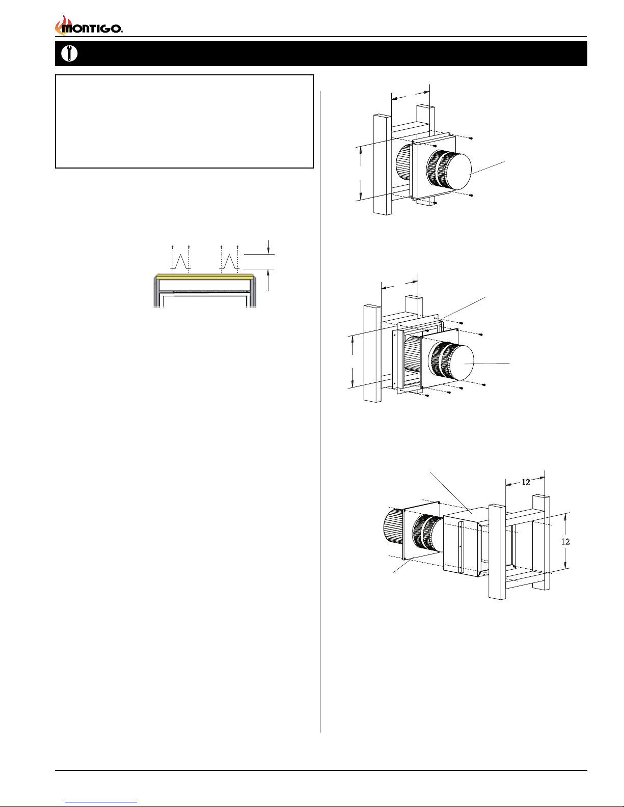
Termination Installation
This section covers the installation of the Various available terminations.
Installing Terminations with Built-In Frames
PTO-3F (5"/8")
1. Frame the termination opening to 11" x 11".
2. Fasten the termination to the studs using a minimum of 4
screws.
Installing Terminations with MSR Frames
MSR
PTO-F (5"/8")
1. Frame the termination opening to 12" x 12".
2. Fasten the termination to the studs using a minimum of 4 screws.
Installing Terminations with MOSR Frames
Installation Requirements
■
H52-DFN fireplace is certified for use with Montigo Standard Series (5"/ 8")
flexible venting components ONLY.
■ Minimum clearance to combustible construction around the vent pipe
is 1" on all sides, except on horizontal venting where the top of the pipe
must have a clearance of at least 2".
■ Use only certified Montigo flexible vent components. (Use of other parts will void
the Montigo warranty, and may impede the operation of the fireplace.)
■ All joints must be secured with a minimum of two screws per joint
■ Horizontal runs must be supported by a minimum of two supports per horizontal
run. A minimum of one screw on each side of support is also required
■ Flex vent sections may be stretched up to 50% of their total length (eg. a
24" section may be stretched to 36")
■ Flexible Venting components can be used in any configuration, and in any
orientation (Male connectors can face in any direction)
Vent Terminations
Selecting A Termination Location
Choosing your vent termination location will help to determine how you
vent your replace. The following gures shows typical replace termination installations and the venting options they provide.
For Detailed diagram of allowed termination locations, see Appendix
Part No. XG0650
MOSR
PTO-F (5"/8")
1. Frame the termination opening to 12" x 12".
2. Fasten the MOSR frame to the interior side of the studs using a
minimum of 4 screws.
3. Insert the termination into the MOSR frame as shown here, and
attach by screwing through the four pilot holes in the termination.
Page 5
H52-DF Gas Fireplace
Installation
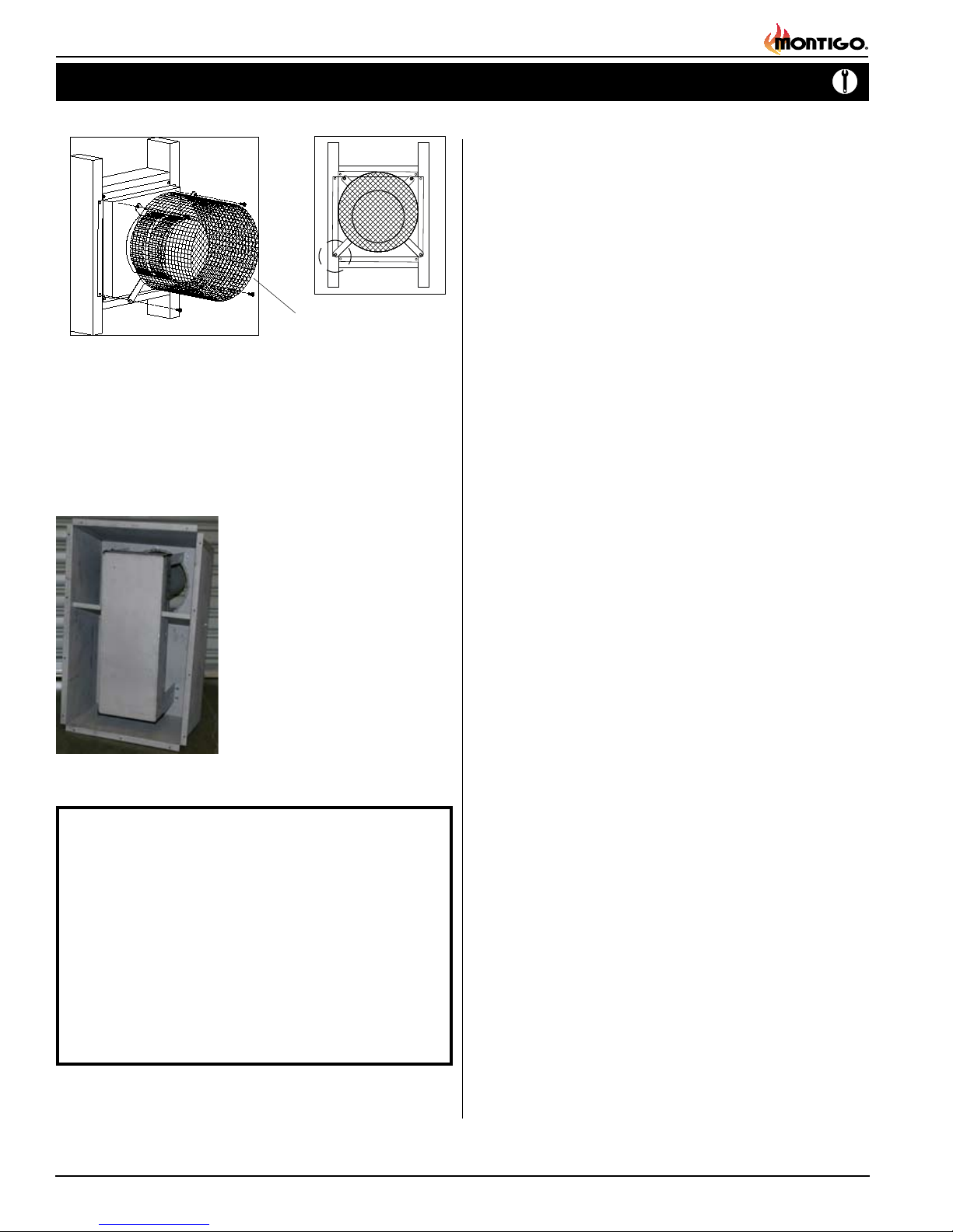
Installing Heat Guards over Terminations
PTKOG (5"/8")
1. Ensure that the two long mounting brackets are facing the bottom
of the termination. (See inset). This will provide more heat protection
at the top of the termination, where temperatures are highest.
2. Attach to the faceplate of the termination using four sheet metal
screws.
Recessed Termination Installation (DVPV58)
The DVPV58 termination is designed
to be Installed ush with the exterior of
the building. This recessed design uses
5"/8" vent and allows the installation to
be clean and ush so it does not interfere
or have an impact with your architectural
design.
Note: The Louvred grille is not supplied by
Montigo and must be sized accordingly.
We require a MIN 80in/sq free air
movement to adequately allow air to
enter, and exhaust the replace. Also note
the material of the louvre must be able to
withstand high operating temperatures.
Figure 5. Linear Power Vent recessed Termination.
IMPORTANT
The H52-DFN requires a specic volume of atmospheric
interchange to operate properly and efciently.
The replace requires a MIN 80in/sq. air movement ■
to function.
Due to high operating temperatures the louvered ■
grill must be manufactured from a material that will
be capable of withstanding high temperatures.
The grille must also be able to shed water, not ■
allowing any moisture to enter the unit.
Installing The Power Vent
The LDVPV58 Linear Power Vent System must ONLY be used with
a Montigo H52-DFN Direct Vent Fireplace. When selecting Venting
components for use with this Linear Power Vent System, take into consideration the various requirements and limitations in the vent installation
section of the Model's manual:
Models Must Be Equipped with Electronic Ignition (HSI/AF)
Only models equipped with an electronic ignition system may be installed
with the LDVPV58 Linear Power Vent System. The absence of a pilot in
this system, allows for greater exibility on venting requirements.
General Information
This installation section covers installation of the LDVPV58 Linear Power
Vent System ONLY. This system is designed to allow the installation of the
H52-DFN gas replace to function with many years of reliable service.
Specications and instructions pertaining SPECIFICALY to the H52-DFN
replace must be followed. Please read these Installation Operation
and Maintenance Instructions thouroughly and carefully before operating this equipment.
Standard Series (5"/8" dia.) Termination System:
LDVPV58 - Linear Power Vent System
Pre/Post Purge Control Box
RHSIT05 -Control module, provides pre/post purge.
Power Cord Harnesses:
LPVH10 -10 foot power cord and harness
LPVH20 -20 foot power cord and harness
LPVH30 -30 foot power cord and harness
LPVH40 -40 foot power cord and harness
LPVH50 -50 foot power cord and harness
LPVH60 -60 foot power cord and harness
LPVH70 -70 foot power cord and harness
LPVH80 -80 foot power cord and harness
Before You Begin
Minimum clearances of 1" from vent to all combustible materials
must be maintained.
The LDVPV58 must only be installed with Montigo venting
components as specified in these instructions.
In order to maintain the power vent system integrity all 5" and 8"
venting connections must also be sealed with high temperature
silicone.
Installation of the LDVPV58 must comply with this manual, and
be completed by a qualified professional.
The MAXIMUM total allowable length; Refer to Linear Power
Vent Installation Section, 3-4.
Minimum length of straight pipe between the Fireplace and the
Power Vent is: 2 feet
Access / Service Panel, must maintain 2" clearance. If 2" clearance
is not possible Minimum 30% free air must be supplied.
Disconnect the power supply when installing and/or servicing
the replace or the power vent system.
Page 6
Part No. XG0650
 Loading...