

Montigo H- DF, H42DF-O Operation Manual
Installation
®
C US
Operation &
Maintenance
Installation and service must be performed by a qualied
installer, service agency, or the gas supplier.
H-Series DF
Outdoor Gas
Fireplace
H42DF-O
Safety Notice:
Glass doors on gas fireplaces are
extremely hot while the fireplace is on
and remain hot even after the fireplace
has been turned off. Safety screens
are available and can reduce the risks
of severe burns. Please keep children
away from the fireplace at all times.
Warning:
Improper installation, adjustment,
alteration, service or maintenance can
cause injury or property damage. Refer to
this manual. For assistance or additional
information consult a qualied installer,
service agency or the gas supplier.
What To Do If You Smell Gas:
• Do not try to light any appliance.
• Do not touch any electrical switch; do not use any phone in your building.
• Immediately call your gas supplier from a neighbor's phone. Follow the gas
supplier's instructions.
• If you cannot reach your gas supplier, call the re department.
For Your Safety:
Do not store or use gasoline
or other flammable vapors
and liquids in the vicinity
of this or any other
appliance.
Check local codes and read all
instructions prior to installation.
Installer: Leave this manual
with the appliance.
Consumer: Leave this man-
ual for future reference.
Warning:
Read this manual before installing, operating or troubleshooting this
appliance. Please retain this owner's manual for future reference.
Congratulations
Congratulations on selecting a Montigo gas replace, an elagent and
well designed gas replace built to your specications. The Montigo
gas replace you have selected is designed to provide the utmost in
safety, reliability, and engineering standards.
As the owner of this new replace, you'll want to read and carefully
follow all the instructions contained in this Installation, Operations and
Maintenance manual. Pay special attention to all cautions, warnings,
and Important warnings.
Safety Alert Key:
This owner's manual should be retained for future reference. We
suggest that you keep it with all your other important documents and
product manuals.
The information contained in this owner's manual, unless noted otherwise, applies to all models, and gas control systems.
Your new Montigo gas replace will give you years of durable, reliable
use. Welcome to the Montigo family of gas replace products.
• DANGER!
Indicates a hazardous situation which, if not avoided will result in death or serious injury.
• WARNING! Indicates a hazardous situation which, if not avoided could result in death or serious injury.
• CAUTION! Indicates a hazardous situation which, if not avoided, could result in minor or moderate injury.
• NOTICE: Used to address practices not related to personal injury.
• Important: Used to address practices not related to personal injury.
Table Of Contents
Congratulations
Safety Alert Key
Introduction ................................................................................. 3
Installation
Installing and Framing the Fireplace ..............................4
Installing the Gasline ...................................................... 5
Vent Installation .............................................................. 5
Installation Requirements .................................. 5
Installing the Remote Switch ............................. 5
Vent Terminations .............................................. 6
Installing the Nailing ange ................................ 6
Top Vent Runs .........................................................7 - 12
Side Vent Runs .......................................................8 - 13
Finishing around the replace
Fireplace Facing .............................................. 13
Mantels and Surrounds ................................... 13
Wiring .........................................................................14
Removing and Installing the Door ................................15
Installing Logset ....................................................16 - 17
Operation .........................................................................16 - 20
Maintenance .................................................................... 20 - 22
Troubleshooting ..................................................... 20 - 21
Spare Parts .................................................................. 22
Warranty .................................................................................23
Appendix
A. Termination Locations .............................................. 24
B State of Massachusetts / Amendment .....................25
H42DF-O Outdoor Gas Fireplace
Introduction
Thank You for choosing a Montigo Gas Fireplace.
About this Fireplace:
The H42DF-O is an outdoor replace' with a linear-style burner. This
replace can be converted to both a Top Vent or Rear Vent application,
and are only available in a H42DF-O model.
The H42DF-O is rated for Natural Gas at 34,000 Max. BTU/H (9.96)
Kilowatts Input and 28,000 Min. BTU/H (7.33) Kilowatts.
► H42DF-O; Top or Rear Vent convertible, Millivolt Pilot (LP Models
Top Vent ONLY).
► H42DF-O-I; Top or Rear Vent convertible, Intermittent Pilot (HSI)
(LP Models Top Vent ONLY).
This manual covers installation, operation and maintenance. Lighting,
operation and care of this replace can be easily performed by the
homeowner. However, all installation and service work should be
performed by a qualied or licensed installer, plumber, or gas tter who
is qualied or licensed by the state, province, region, or governing body
in which the appliance is being installed.
This manual covers all models and unless otherwise specied, the
designation H42DF-O refers to all variations of the model above. Sections
which are specic to a particular variation are marked with a
symbol, plus the appropriate model number.
CAUTION!
Due to its high operating temperatures, the appliance
should be located out of traffic & away from furniture and
draperies.
Children and adults should be alerted to the hazards
of the high surface temperature, which could cause
burns or clothing ignition.
Young children should be carefully supervised when
they are in the same room as the appliance.
Clothing or other flammable materials should not be
placed on or near the appliance.
WARNING!
When this appliance is installed directly on carpeting, tile or any
combustible material other than wood ooring, it must be installed
on a metal or wood panel extending the full width and depth of
the appliance.
Warranty and Installation Information:
The Montigo warranty will be voided by, and Montigo disclaims any
responsibility for, the following actions:
► Modication of the replace and/or components including Direct-Vent
assembly or glass doors.
► Use of any component part not manufactured or approved by Montigo in
combination with this Montigo replace system.
► Installation other than as instructed in this manual.
Consult your local Gas Inspection Branch on installation requirements
for factory-built gas replaces. Installation & repairs should be done by
a qualied contractor.
Installations in Canada must conform to the current CAN/CGA B-149.1
and .2 Gas Installation Code and local regulations. If the optional aircirculating fan kit is installed, it must be electrically grounded in accordance
with CSA C22.1 Canadian Electrical Code Part 1 and/or Local Codes.
Installations in the USA must conform to local codes, or in the absence
of local codes to the National Fuel Gas Code, ANSI Z223.1-1988. If the
optional air-circulating fan is installed, it must be grounded in accordance
with local codes or, in the absence of local codes, with the National
Electrical Code, ANSI/NFPA 70-1987. See Appendix for installation
within the State of Massachusetts. This replace must comply with
NFPA-54 Chapter 10.
Part No. XG0149
Page 3
H42DF-O Outdoor Gas Fireplace
36 1/2
37 3/4
35 1/4
1 1/4
1 1/4
1 1/4
1
5 1/2”
5 1/4”
25 3/4
18 1/2”
25”
J
K
C
L
C
L
8”
5”
46 3/8
50 1/8
10
40 1/8
Header
Header
Shelf
MELShort
Shelf
33
46 3/8
19
Installation
Installing The Fireplace Shell
The replace may be installed in any location that maintains proper clearances to air conditioning ducts, electrical wiring and plumbing. Safety,
as well as efciency of operation, must be considered when selecting
the replace location. Try to select a location that does not interfere
with room trafc, has adequate ventilation, and offers an accessible
pathway for Direct Vent installation. Refer to page 4 - Vent Installation
for more information.
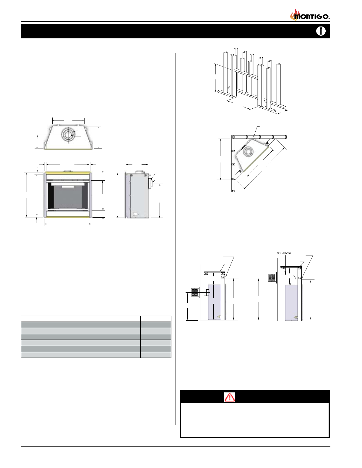
The replace dimensions are shown below:
Top View
18 1/2”
8”
5”
36 1/2
28 3/4
Side View
Front View
Figure 1. Fireplace dimensions.
Framing
46 3/8”
37 3/4”
* When sheetrock is
not used behind the
fireplace, framing
depth may be reduced
by 5/8"
20 1/8”
Figure 2. Framing dimensions.
48 1/8”
42”
68”
Figure 3. Minimum Corner framing dimensions, using a 45° elbow.
When installing a shelf over the top of the replace, the following
guidelines must be adhered to: For Rear Vent applications the
minimum clearance from the top of the replace to a shelf is 9". For
Top Vent applications, the minimum clearance is 17 1/2". (Minimum
2" clearance must still be maintained around the vent pipes.)
Clearances
These clearances apply to all dimensions except the framed opening,
where the clearance to combustibles is 0". The H42DF-O clearance to
unprotected combustible walls which are perpendicular to the replace
opening, must not project beyond the shaded area shown in Fig. 24.
For protection against freezing temperatures, it is recommended that
outer walls of the chase be insulated with a vapor barrier. This will reduce
the possibility of a cold-air convection current on the replace.
Top - Rear Vent * 9"
Top - Top Vent 17
Back 1"
Sides 1"
Floor 0"
Mantle** 4"
* Clearance from top of the Fireplace to a combustible ceiling within the fireplace
enclosure.
** Refer to Pages, 10 & 11.
Page 4
H42DF-O
1
/
2"
Rear Vent
Top Vent
Figure 4. Framing for shelves over the replace.
WARNING!
When this appliance is installed directly on carpeting, tile or any
combustible material other than wood ooring, it must be installed
on a metal or wood panel extending the full width and depth of
the appliance.
Part No. XG0149
Installation
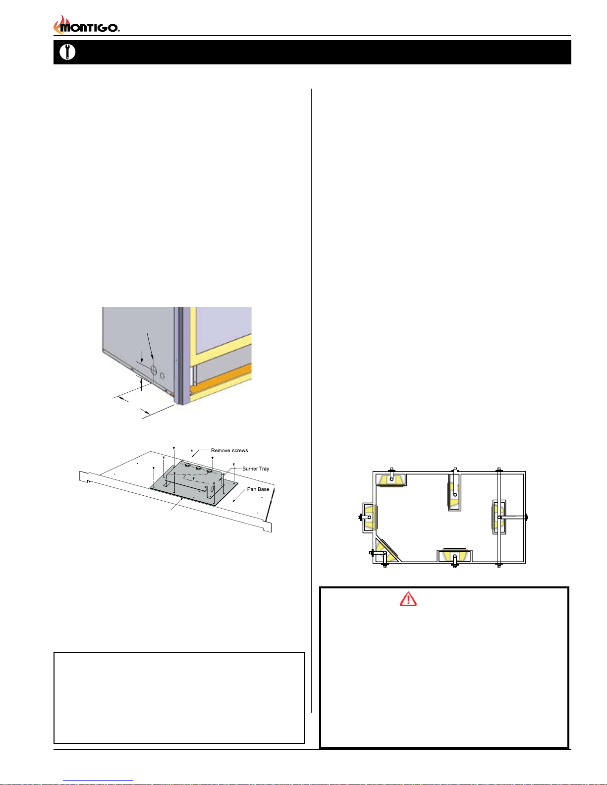
Burner Tray Gasket
Figure 5b. Gas line access.
H42DF-O Outdoor Gas Fireplace
Installing The Gas Line
The gas line must be installed before nishing the H42DF-O Fireplace.
Natural Gas requires a minimum inlet gas supply pressure of 5.5" W.C.
& a manifold pressure of 3.5" W.C. Propane Gas requires a minimum
inlet gas supply pressure of 11" W.C. & a manifold pressure of 10" W.C.
Provision must also be made for a 1/8" N.P.T. plugged tapping and be
accessible for test gauge connection immediately upstream of the gas
supply controls to the appliance. The replace gas connection and
the main operating gas valve is located behind the removable trim at
the bottom of the unit and need only be attached to the gas line with
an approved tting, as required by the applicable installation codes.
To access the replace gas connection the main burner must be
removed as shown below in gure 5b.
• Only use gas shut-off valves approved for use by the state, province,
region, or governing body, in which the appliance is being installed, or
as required by the applicable installation codes.
• Flexible gas connectors must not exceed 3 feet in length, unless it is
allowable within applicable installation codes.
Gasline Acces
0.875 dia.
2
7
to center
Figure 5a. Gas line access.
Vent Installation
This section covers the installation of direct venting and terminations.
Installation Requirements
■
H42DF-O fireplace are certified for use with Montigo Standard Series (5" /
8") venting components.
■ Minimum clearance to combustible construction around the vent pipe
is 1" on all sides, except on horizontal venting where the top of the pipe
must have a clearance of at least 2".
■ Use only certied Montigo vent components. (Use of other parts will void
the Montigo warranty, and may impede the operation of the fireplace.)
■ All joints must be secured with a minimum of two screws per joint
■ Vent terminations must not be recessed in walls or siding
■ Horizontal runs must be supported by a minimum of two supports per horizontal
run. A minimum of one screw on each side of support is also required
■ Flex vent sections may be stretched up to 50% of their total length (eg. a
24" section may be stretched to 36")
■ Maximum horizontal run with no vertical rise is 6 feet.
■ Flex vent sections over 6 feet must fall within the limits set by the venting
graph and must have a minimum vertical rise of 3 inches per foot of flex.
■ Solid vent sections may be cut less than half way from the female end
■ Venting components can be used in any combination of solid/rigid pipe or flex
pipe and in any orientation (Male connectors can face in any direction)
Vent Terminations
Selecting A Termination Location
Choosing your vent termination location will help to determine whether
you need to use a top vent or rear vent replace. Figure 6a, below, shows
typical replace locations and the venting options they provide.
For a more detailed diagram of allowed termination locations, see Ap-
pendix A.
The appliance and its individual shut-off valve must be disconnected
from the gas supply piping system during any pressure testing of that
system at test pressures in excess of 1/2 psig (3.5 kPa).
The appliance must be isolated from the gas supply piping system by
closing its individual manual shut-off valve during any pressure testing
of the gas supply piping system at test pressures equal to or less than
1/2 psig (3.5 kPa).
Note: After gas line is connected, each appliance connection,
valve and valve train must be checked while under normal
operating pressure with either a liquid solution, or leak
detection device, to locate any source of leak. Tighten any
areas where bubbling appears or leak is detected until
bubbling stops completely or leak is no longer detected.
DO NOT use a flame of any kind to test for leaks.
Part No. XG0149
Figure 6a. Fireplace locations and vent terminations.
CAUTION!
Due to its high operating temperatures, the appliance
should be located out of traffic & away from furniture and
draperies.
Children and adults should be alerted to the hazards
of the high surface temperature, which could cause
burns or clothing ignition.
Young children should be carefully supervised when
they are in the same room as the appliance.
Clothing or other flammable materials should not be
placed on or near the appliance.
Page 5
H42DF-O Outdoor Gas Fireplace
12
12
11
11
1212
12
Installation
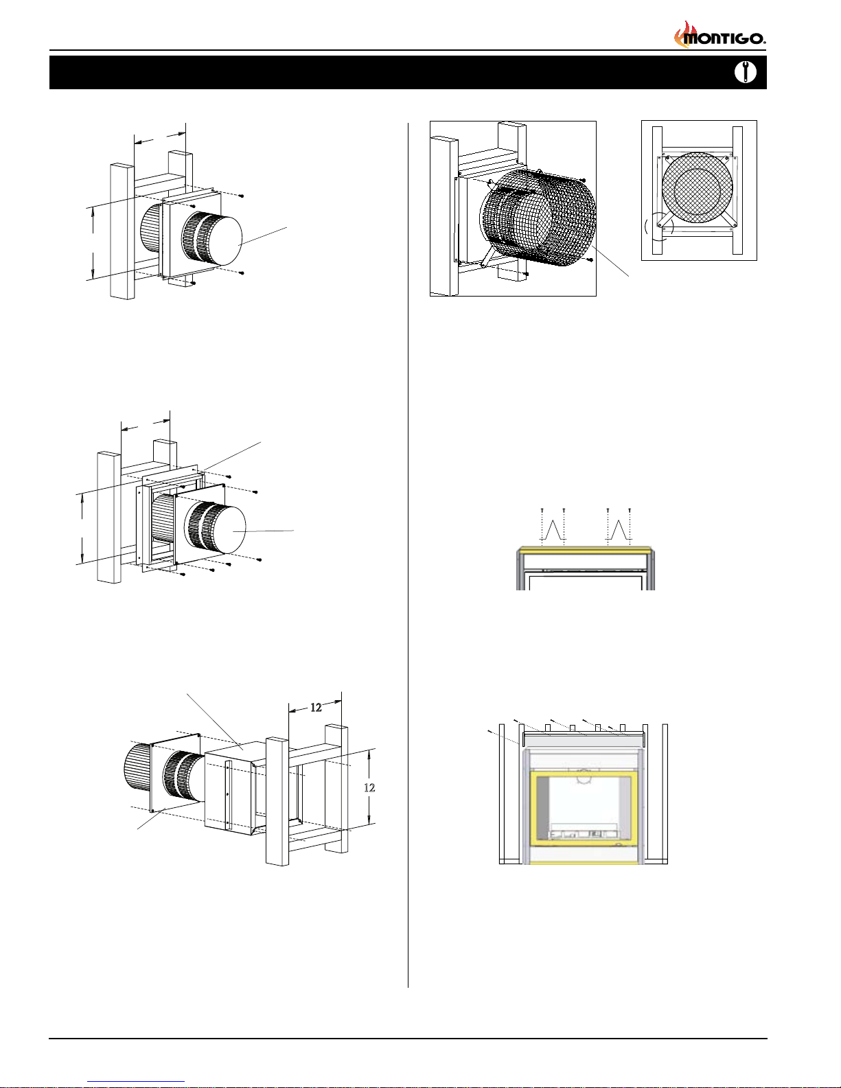
Installing Terminations with Built-In Frames
MTO-3F (4"/7")
PTO-3F (5"/8")
1. Frame the termination opening to 11" x 11".
2. Fasten the termination to the studs using a minimum of 4
screws.
Installing Terminations with MSR Frames
MSR
Installing Heat Guards over Terminations
MTKOG (4"/7")
PTKOG (5"/8")
1. Ensure that the two long mounting brackets are facing the bottom
of the termination. (See inset). This will provide more heat protection
at the top of the termination, where temperatures are highest.
2. Attach to the faceplate of the termination using four sheet metal
screws.
Installing The Standoffs
To avoid elevated mantel temperatures, all H42DF-O gas
replaces are required to have the supplied standoffs installed.
The replace is supplied with two standoffs. Bend and install these
standoffs on top of the replace ensuring that the height of the standoff
maintains a 6" clearance.
MTO-3 (4"/7")
PTO-3 (5"/8")
1. Frame the termination opening to 12" x 12".
2. Fasten the termination to the studs using a minimum of 4 screws.
Installing Terminations with MOSR Frames
MOSR
MTO-3 (4"/7")
PTO-3 (5"/8")
1. Frame the termination opening to 12" x 12".
2. Fasten the MOSR frame to the interior side of the studs using a
minimum of 4 screws.
3. Insert the termination into the MOSR frame as shown here, and
attach by screwing through the four pilot holes in the termination.
Page 6
Figure 6b. Installing the stando's.
Installing the Nailing Flange
Extension
Once the replace is placed into the framed opening, the supplied
nailing extension must be placed along the top edge of the replace,
and nailed in place to the framing, as illustrated below.
Figure 6c. Installing the Nailing Flange Extension.
Installing The Remote Switch
The H42DF-O's gas valve, located behind the lower trim, may be
connected to a wall switch. The valve generates its own power on a
millivolt circuit. Use only low voltage wire, and DO NOT connect
any external power to it.
Refer to Figure 26 for wiring requirements.
Note: The switch location must not exceed 30' from the replace.
Part No. XG0149
Installation
H42DF-O Outdoor Gas Fireplace
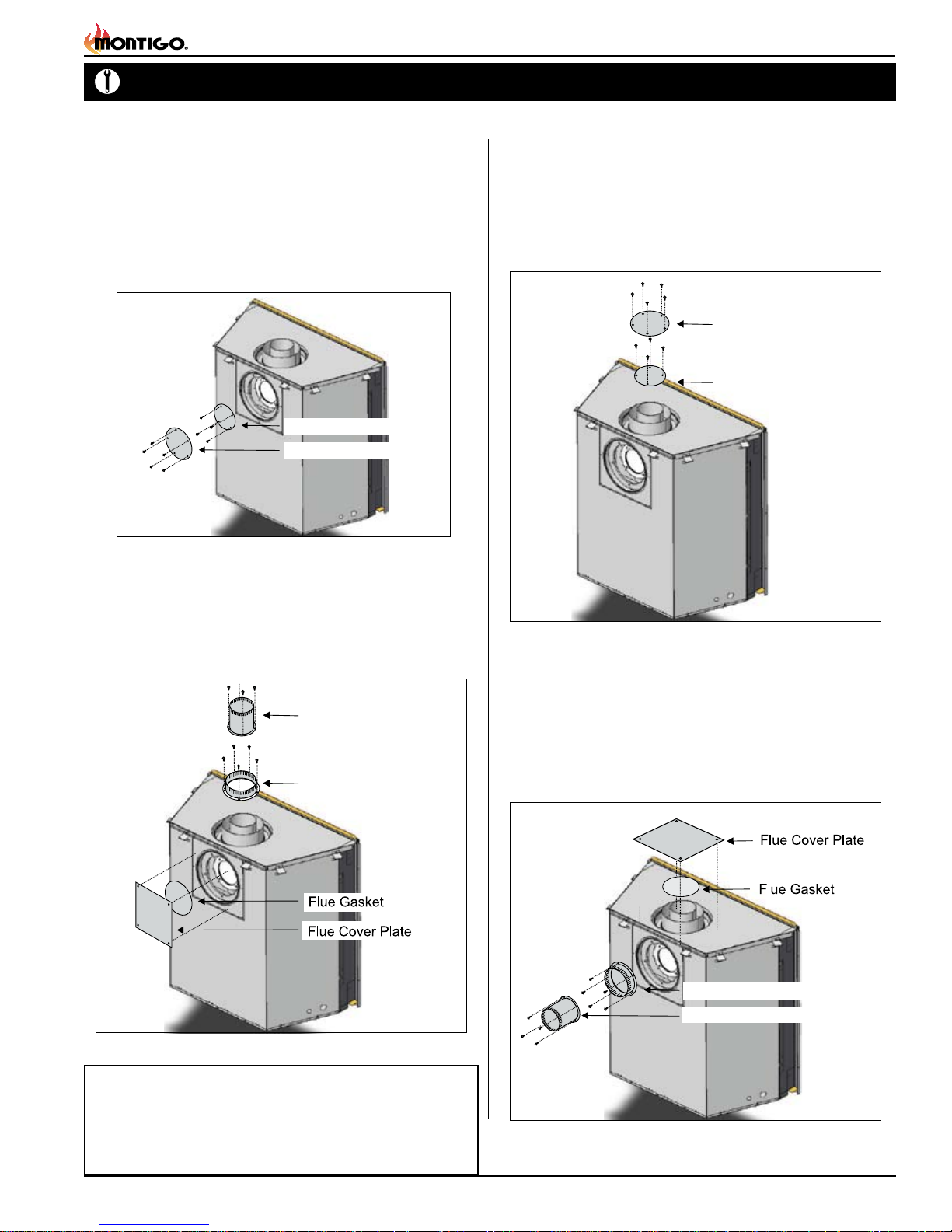
Converting to Top Vent/ Rear Vent
H-Series DF Top Vent
Use the following instructions to convert an H42DF-O for Top Vent
use:
Install the 4" or 5" inner ue cap on the rear ue outlet and secure 1.
the cap in place with ve screws, as shown in gure 7a.
Install the 7" or 8" outer ue cap on the rear ue outlet, and secure 2.
it with ve screws, as shown in gure 7a.
5” Inner Flue Cap
8” Outer Flue Cap
Figure 7a. Flue cap installation for Top Vented replace.
Install the ue gasket material and ue cover plate on the rear vent 3.
outlet . Fasten the plate with four screws, as illustrated below.
Install the 4" or 5" inner ue collar and the 7" or 8" outer ue 4.
collar in place on the top vent outlet using 5 screws, as illustrated
below.
5” Inner Flue Collar
8” Outer Flue Collar
H-Series DF Rear Vent
Use the following instructions to convert an H42DF-O for Top Vent
use:
Install the 4" or 5" inner ue cap on the top ue outlet and secure 1.
the cap in place with ve screws, as shown in gure 8a.
Install the 7" or 8" outer ue cap on the top ue outlet, and secure 2.
it with ve screws, as shown in gure 8a.
8” Outer Flue Cap
5” Inner Flue Cap
Figure 8a. Flue cap installation for Rear Vented replace.
Install the ue gasket material and ue cover plate on the top 3.
vent outlet. Fasten the plate with four screws, as illustrated in
gure 8b.
Install the 4" or 5" inner ue collar and the 7" or 8" outer ue 4.
collar in place on the rear vent outlet using 5 screws, as illustrated
below.
Figure 7b. Flue collar installation for Top Vented replace.
Important: Natural Gas and Propane equipped models
may be installed using Top or Rear Vent applications.
However, the Propane equipped H42DF-O models must
be installed in a top vent application only.
Part No. XG0149
8” Outer Flue Collar
5” Inner Flue Collar
Figure 8b. Flue collar installation for Rear Vented replace.
Page 7
H42DF-O Outdoor Gas Fireplace
Installation
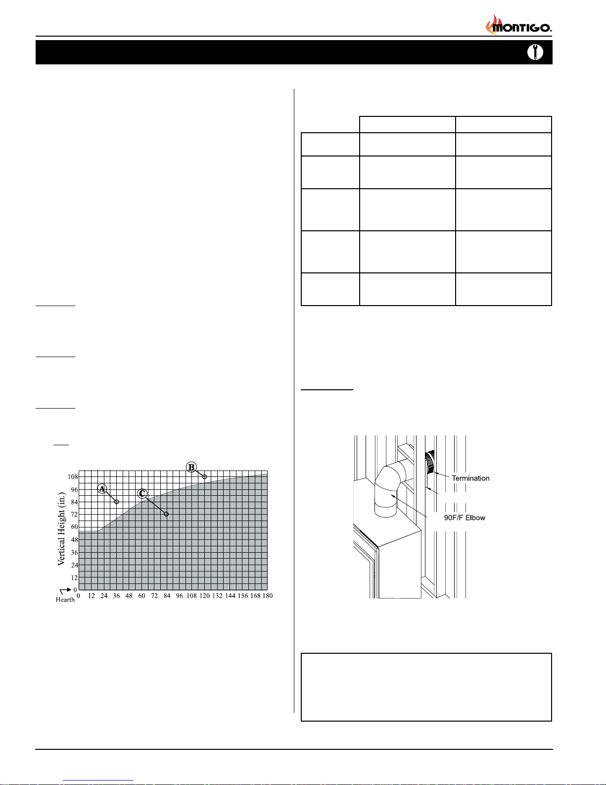
Top Vent Venting Runs
For the H42DF-O Top Vent, there are two types of installations: A)
Through-The-Wall Installations and B) Vertical (Through-The-Roof)
Installations.
A) Through-The-Wall Installations
Before you install any venting, you must determine whether the venting
run will be acceptable. Unacceptable venting can affect the replace's
combustion.
The Venting Graph
Measure the vertical height from the replace hearth to the centre of
the termination and the horizontal run from the replace ue collar to
the wall ange of the termination. Plot on the Venting Graph (Fig. 9a)
with an 'X'.
If the 'X' falls on or above the top boundary of the shaded area, the
installation is acceptable.
Example A: (Acceptable Installation)
If the vertical dimension from the hearth is 84" and the horizontal run to
the wall flange of the vent termination is 36", this would be an acceptable
installation.
Example B: (Acceptable Installation)
If the vertical dimension from the hearth is 108" and the horizontal run to
the wall flange of the vent termination is 120", this would be an acceptable
installation.
Example C: (Unacceptable Installation)
If the vertical dimension from the floor of the fireplace is 72" and the
horizontal run to the wall flange of the vent termination is 84", this would
NOT be an acceptable installation.
Available Top Vent Components
The following venting components are available for the H42DF-O Top
Vent:
4" / 7" Venting 5" / 8" Venting
A - Termination MTO-3 (3" Length)
B - Stucco Kits MSR (Stucco Frame)
C - Flex Sections MFL-1 (12" Section)
D - Rigid
Sections
E - Elbows MEL-90MM (m/m 90° Elbow)
MTO-3F (3" Length)
MOSR (Stucco Can)
BSR ( Brick Can)
MFL-2 (24" Section)
MFL-3 (36" Section)
MFL-4 (48" Section)
MEXT-1 (12" m/f Section)
MEXT-2 (24" m/f Section)
MEXT-3 (36" m/f Section)
MEXT-4 (48" m/f Section)
MEL-90FF (f/f 90° Elbow)
MEL-90FM (f/m 90° Elbow)
NOTES: All dimension lengths for vertical or horizontal runs are
measured from centre of the vent pipe.
Venting runs must fall within the limits set by the venting
graph (see Figure 7).
Example 1:
For our shortest venting conguration use components A and E (see
Figure 10).
PTO-3 (3" Length)
PTO-3F (3" Length)
MSR (Stucco Frame)
MOSR (Stucco Can)
BSR ( Brick Can)
PFL-1 (12" Section)
PFL-2 (24" Section)
PFL-3 (36" Section)
PFL-4 (48" Section)
PEXT-1 (12" m/f Section)
PEXT-2 (24" m/f Section)
PEXT-3 (36" m/f Section)
PEXT-4 (48" m/f Section)
PEL-90MM (m/m 90° Elbow)
PEL-90FF (f/f 90° Elbow)
PEL-90FM (f/m 90° Elbow)
Figure 9c. H42DF-ODTop Vent Venting Graph
NOTES: All dimension lengths for vertical or horizontal runs are
measured from centre of the vent pipe.
Venting runs must fall within the limits set by the venting
graph (see Figure 7).
Page 8
RHS8 Heat Shield
PEL
PEL-90F/F Elbow
Figure 10. Typical Top Vent installation. If the 90° elbow is installed
directly on the replace, for height to the center of the
termination see chart on page 3.
Important:
An inspection of the explosion relief appers and door must be
made prior to lighting the replace. This will ensure the door gas-
keting material will provide an adequate seal during operation.
Part No. XG0149
 Loading...