

Montigo H38DF-PRC, HL38DF-PRC, HS38DF-PRC, HLS38DF-PRC, H38PRN Maintance Manual
...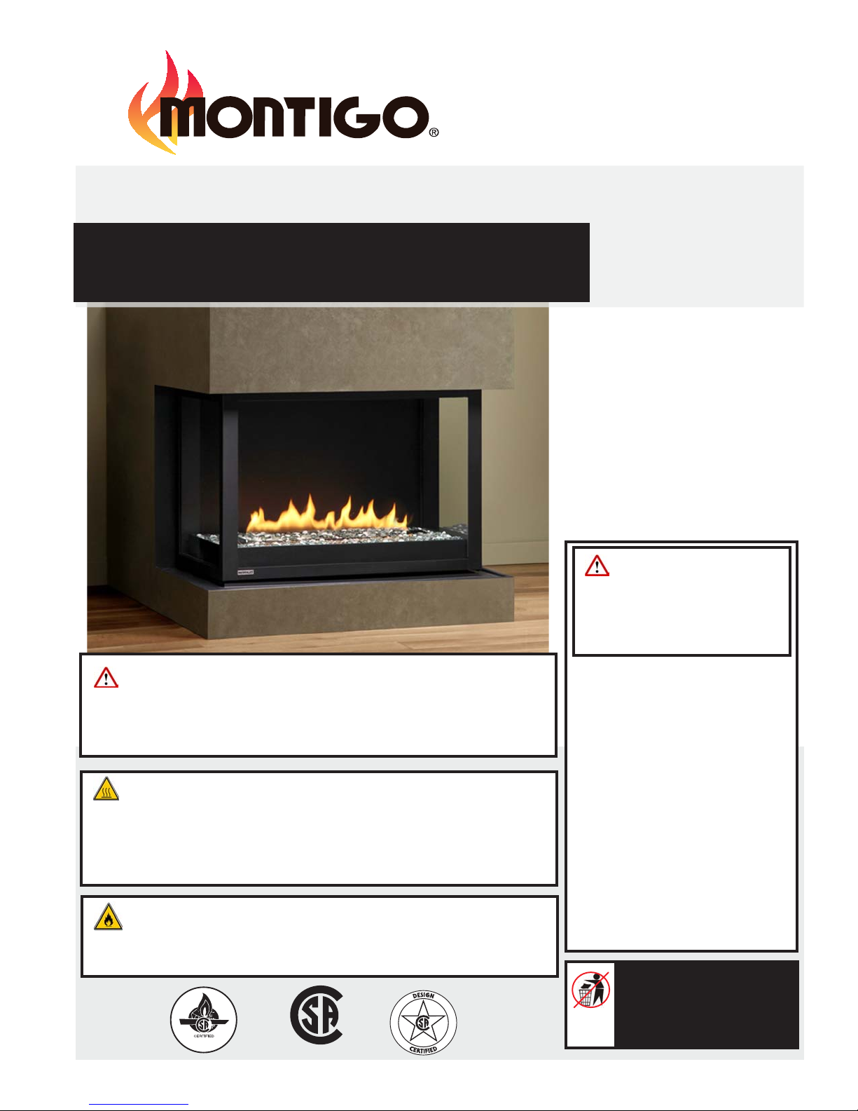
Installation Operation & Maintenance Manual
Check local codes and read all instructions prior to installation.
H38DF-PRC Gas Fireplace
www.montigo.com
H38DF-PRC
HL38DF-PRC
HS38DF-PRC
HLS38DF-PRC
Warning: If the infor-
mation in these instructions is not
followed exactly, a re or explosion
HL38DF-PRC Shown
Warning:
Improper installation, adjustment, alteration, service or maintenance can cause
injury or property damage. Refer to this manual. For assistance or additional
information consult a qualied installer, service agency or the gas supplier.
Safety Notice:
Glass doors on gas replaces are extremely hot while the replace is on and remain
hot even after the replace has been turned off. Safety screens are available and
can reduce the risks of severe burns. Please keep children away from the replace
at all times.
For Your Safety:
Do not store or use gasoline or other ammable vapors and liquids in the
vicinity of this or any other appliance.
®
C US
XG0211 Canadian Heating Products Inc. Langley, BC V4W 4A Montigo Del Ray Corp. Ferndale, WA 98248 080510
may result causing property damage, personal injury or death.
WHAT TO DO IF YOU SMELL GAS
• Do not try to light any appliance.
• Do not touch any electrical
switch; do not use any phone in
your building.
• Immediately call your gas
supplier from a neighbor's
phone. Follow the gas supplier's
instructions.
• If you cannot reach your gas
supplier, call the re department.
Installation and service must be
performed by a qualied installer,
service agency or the gas supplier.
• Installer: Leave this manual
with the appliance.
• Consumer: Retain this
manual for future reference.
H(L)38DF-PRC Indoor Panorama Gas Fireplace
Read this manual before installing, operating or troubleshooting this appliance.
Please retain this owner's manual for future reference.
Table of Contents
Safety Alert Key
Introduction
Models............................................................................3
Installation
Before you Start ............................................................. 4
Installation Checklist ...................................................... 4
Section 1: Installation Overview and Product Dimensions ......5
Section 2: Framing the Fireplace ............................................. 6
Installing the Standoffs ...................................... 6
Section 3: The Direct Vent System ................................... 7 - 11
Section 3-1: Converting from Top Vent to Rear Vent ....7
Section 3-2: Installing a Roof mounted Termination 8 - 9
▪ Section 3-2-1: Venting Layout ...................................... 8
▪ Roof mounted Terminations
Standard Top Vent (no elbows or offsets)............. 8
Top Vent (two elbows one offset) ......................... 8
Top Vent (multi-elbows and offsets) ..................... 8
Standard Roof Vent (one elbows no offsets) ....... 9
▪ Section 3-2-2: Venting Components ............................. 9
Section 3-3: Installing a Wall mounted Termination ....10
▪ Standard PTO Installation ....................................10
▪ Pre-installed MSR Frame .................................... 10
▪ Pre-installed BSR Frame ..................................... 10
▪ Installing MOSR Frame ....................................... 10
▪ Installing VSS Termination Shield ......................... 10
▪ Installing PTKOG Heat Guard .............................. 10
▪ Section 3-3-1: Venting Layout ............................ 11 - 12
▪ Top Vent, Wall mounted termination Graph ............ 11
▪ Top Vent, Wall mounted termination (one elbow) ..... 11
▪ Top Vent, Wall mounted termination (multi elbow) .... 11
▪ Rear Vent, Wall mounted Termination Graph ......... 12
▪ Standard Rear Vent, (no elbows or offsets) ........... 12
▪ Rear Vent, Wall mounted termination (two elbows) . 12
▪ Section 3-3-2: Venting Components ........................... 13
............................................................................... 3
Warning:
▪ Section 3-3-3: Heat Shields ....................................... 14
▪ Installing a RHS8 Wall Mounted Heat Shield ......... 14
▪ Installing a RHS101 Wall Mounted Heat Shield ......14
Section 4: Wiring ................................................................... 15
▪ Honeywell gas control and pilot .......................... 15
▪ SIT - IPI gas control and pilot ............................... 15
Section 5: Installing the Gas Line .......................................... 16
Section 5-1: Fuel Conversion ........................................ 16
Section 5-2: Gas Pressure ............................................ 16
Section 5-3: Gas Connection ...................................... 16
Section 6: Finishing ............................................................... 17
Section 7: Installing and Removing the Door ........................ 18
Section 8: Installing the Accessories
▪ Installing the H38DF-PRC Log Set ........................... 19
▪ Installing the HL38DF-PRC Firestones......................20
Section 9: Operation
▪ Start-up Sequence with Continuous Pilot ..................21
▪ Start-up Sequence with Honeywell Electronic Ignition 22
▪ Start-up Sequence SIT-IPI Gas valve ....................... 23
Maintenance ................................................................... 24 - 25
▪ General ................................................................. 24
▪ Cleaning ................................................................ 24
▪ Gas Control Valve................................................... 25
▪ Pilot Burner Adjustment ........................................... 25
▪ Troubleshooting .....................................................25
Appendix
A. Termination Locations .......................................... 26
B. Warranty ............................................................ 27
C. State of Massachusetts. ...................................... 28
Page 2
Part No. XG0211 - 080510
H(L)38DF-PRC Indoor Panorama Gas Fireplace
Introduction
Safety Alert Key:
• WARNING!
Indicates a hazardous situation which, if not avoided could result in death or serious injury.
• CAUTION! Indicates a hazardous situation which, if not avoided, could result in minor or moderate injury.
• NOTICE: Used to address practices not related to personal injury.
• Important: Used to address practices not related to personal injury.
INTRODUCTION
Congratulations on your purchase of a Montigo Fireplace.
With over 30 years of experience, Montigo is committed to providing
you with a gas replace that is not only a beautiful addition to your
space, but that is also designed and manufactured to the highest
safety, reliability and engineering standards.
We strongly encourage you to read and carefully follow the
instructions laid out in this Installation, Operation and Maintenance
Manual and retain it for your future reference. Pay special attention
to all cautions, warnings, and notices throughout this manual
intended to ensure your safety.
This manual covers installation, operation and maintenance.
Lighting, operation and care of this replace can be easily
performed by the homeowner. All installation and service work
should be performed by a qualied or licensed installer, plumber
or gastter as certied by the state, province, region or governing
body where the replace is being installed.
This installation, operation and maintenance manual is applicable
to the models described below. Refer to your rating plate to
verify included options. Throughout this manual instructions are
applicable to all models designated as H*38PR* unless otherwise
noted.
Warranty and Installation Information: (See Appendix B)
The Montigo warranty will be voided by, and Montigo disclaims any
responsibility for, the following actions:
► Modication of the replace and/or components including DirectVent assembly or glass doors.
► Use of any component part not manufactured or approved by
Montigo in combination with this Montigo replace system.
► Installation other than as instructed in this manual.
Consult your local Gas Inspection Branch on installation requirements
for factory-built gas replaces. Installation & repairs should be done by
a qualied contractor.
WARNING
HOT GLASS WILL
CAUSE BURNS.
DO NOT TOUCH GLASS
UNTIL COOLED.
NEVER ALLOW CHILDREN
TO TOUCH GLASS.
tes
g
ol/
n la
w re
oiti
d
rn
ra
MODEL
H38PRN
H38PRNE
H38PRNI
H38PRL
H38PRLE
H38PRLI
HL38PRN
HL38PRLI2
X
X
X
X
I
2
Natural Gas
Liquid Propane
34000
34000
34000
X
32000
X
32000
X
32000
34000
X
32000
Gas Rating
(BTU/hr)
Bu
T
X
X
X
X
X
X
X
X
NOTE: H*(S)38PR* Units are stainless steel construction
Part No. XG0211 - 080510
Standing Pilot
Linear Burner w/
Ignition
Glass Accessories
X
X
SIT Electronic
Honeywell Hot
X
X
Ignition
Surface Ignition
X
X
X
X
Page 3
H(L)38DF-PRC Indoor Panorama Gas Fireplace
Installation
IMPORTANT MESSAGE: SAVE THESE INSTRUCTIONS
The H*38PR* Direct Vent replace must be installed in
accordance with these Instructions. Carefully read all the
Instructions in this manual rst. Consult the Local Gas Branch to
determine the need for a permit prior to starting the installation.
It is the responsibility of the installer to ensure this replace is
installed in compliance with the manufacturers instructions and
all applicable codes.
BEFORE YOU START:
INSTALLATION AND REPAIRS SHOULD BE DONE
BY AN AUTHORIZED SERVICE TECHNICIAN. THE
APPLIANCE SHOULD BE INSPECTED BEFORE USE
AND AT LEAST ANNUALLY BY A PROFESSIONAL
SERVICE TECHNICIAN. MORE FREQUENT CLEANING
MAY BE REQUIRED DUE TO EXCESSIVE LINT
FROM CARPETING, BEDDING MATERIAL, ETC. IT
IS IMPERATIVE THAT CONTROL COMPARTMENTS,
BURNERS AND CIRCULATING AIR PASSAGEWAYS
OF THE FIREPLACE ARE KEPT CLEAN.
CAUTION!
Due to its high operating temperatures, the appliance should
be located out of trafc & away from furniture and draperies.
Children and adults should be alerted to the hazards
of the high surface temperature, which could cause
burns or clothing ignition.
Young children should be carefully supervised when
they are in the same room as the appliance.
Clothing or other ammable materials should not be
placed on or near the appliance.
Installation Checklist
Determine the desired install location of your replace.
See Section 1, Dimensions on Page 5, and refer to the Framing
Section 2 for details.
Select the location of your termination and resulting vent run.
Your selected termination location must be the highest point
in the Direct Vent installation.
Should it be impossible to meet the venting requirements laid
out in Section 3: Venting, please contact Montigo regarding the
use of a Montigo Power Vent.
Lay out the Vent run; calculating the required elbows and straight
runs of 5"/8" flex or rigid pipe.
Layout Electrical Requirements Refer to Section 4, Wiring"
for Details.
Refer to Section 5, Installing the Gas Line for details on the gas
connection and access.
Refer to local codes and guidelines for installation requirements.
Installation and repairs should be done by a qualied
contractor and must conform to:
• Installations in Canada must conform to the current
CAN/CGA B-149.1 and .2 Gas Installation Code and local regulations.
• Installations in the USA must conform to local codes,
or in the absence of local codes to the National Fuel Gas Code, ANSI
Z223.1-1988
• See Appendix C for installation within the State of
Massachusetts. This replace must comply with NFPA-54 Chapter
10.
.
WARNING!
When this appliance is installed directly on any combustible
material other than wood ooring, it must be installed on a
metal or wood panel extending the full width and depth of
the appliance.
Page 4
Part No. XG0211 - 080510
H(L)38DF-PRC Indoor Panorama Gas Fireplace
Installation
Section 1: Installation Overview and Product Dimensions
Please review the Pre-Installation Checklist on Page 4 for general information on preparing for a successful installation of your replace.
The H*38PR* replace may be installed in any location that maintains proper clearances to air conditioning ducts, electrical wiring and plumbing.
Safety, as well as efciency of operation, should be considered when selecting the replace location. Try to select a location that does not interfere
with room trafc, has adequate ventilation and offers an accessible path for Direct Vent installation.
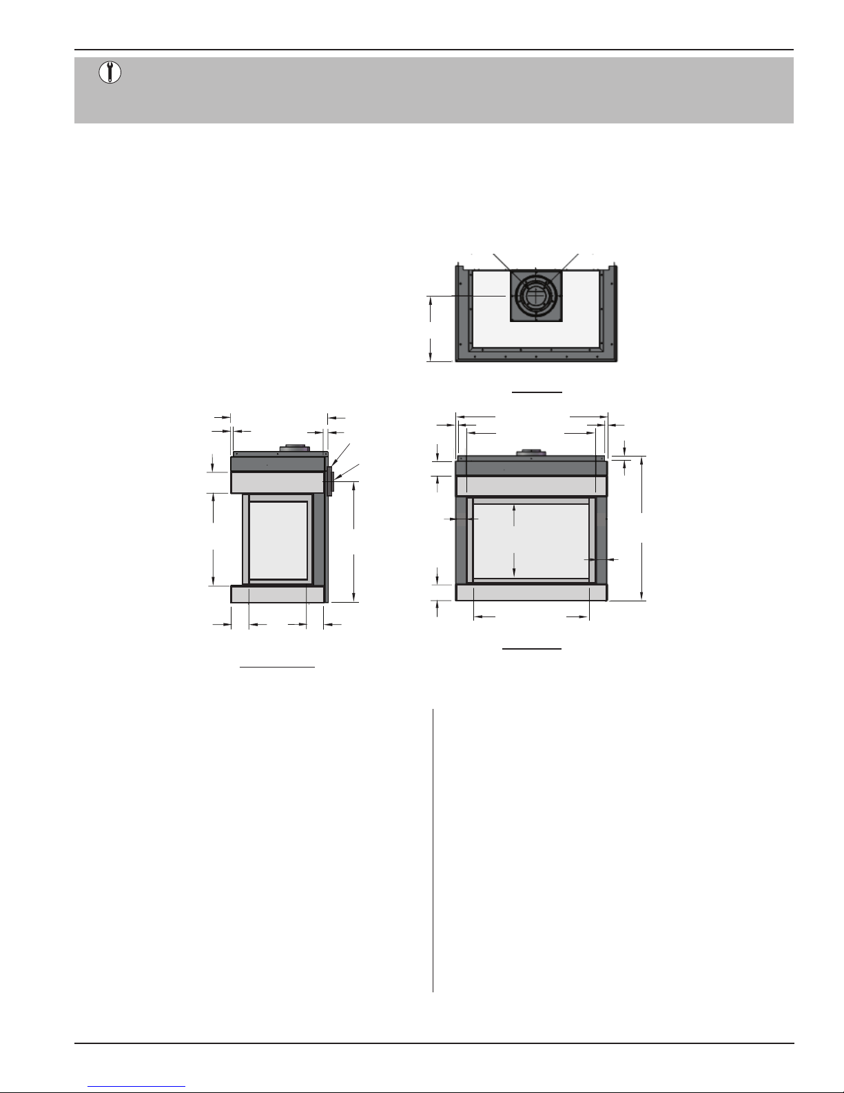
The replace dimensions are shown below:
26 1/4” Depth
5/8”
6”
24 3/4”
Opening
4 1/2”
1”
16 1/4”
Glass
LH-Side View
17 1/4”
5/8”
Ø 8”
Ø 5”
33”
Rear Vent
4 1/2”
4”
3”
4 3/4”
Figure 1. Fireplace dimensions.
Ø 5”
42 1/8” Width
36 1/8” Door
21 1/2”
Glass
32 1/8” Glass
Front View
C
L
Top View
Ø 8”
5/8”
1”
41”
Height
Part No. XG0211 - 080510
Page 5

H(L)38DF-PRC Indoor Panorama Gas Fireplace
Section 2: Framing
Installation
1). Frame in the enclosure for the unit with framing materials. The
framed opening for the assembled replace is 40 7/8" wide, x 44"
high x 24 5/8" deep, see Figure 2
.
NOTE: When constructing the framed opening, please ensure
there is access to install the gas line when the unit is installed.
See Figure 22.
40 3/4”
44”
24 1/2”
Figure 2. Framing dimensions.
Clearances
When installing a shelf over the top of the replaces, the following
guidelines must be adhered to:
For Rear Vent applications, the minimum clearance is 2" from the rear of
the replace to a wall, or any combustible materials, and 11" clearance
from the top of the replace to the underside of any combutible shelf
materials.
For Top Vent applications, the minimum clearance is 2" from the rear of
the replace to a wall, or any combustible materials, and 17 1/2" to the
underside of any combutible shelf materials.
(Minimum 2" clearance must still be maintained around the vent
pipes.)
Installing The Standoffs
To avoid elevated mantel temperatures, all H*38PR* gas
replaces are required to have the supplied standoffs installed.
The replace is supplied with two standoffs. Bend and install these
standoffs on top of the replace ensuring that the height of the standoff
maintains a 3" clearance.
3.0”
Figure 6. Installing the H*38PR* standoffs.
Clearance to Combustibles
Top- top vent 11"
Top- rear vent 17 1/2"
Header (from oor) 44"
Sides 0"
Front** 0"
Back 1"
Venting - top 2"
Venting- sides, bottom 1"
Framing Header
12”
Max
33”
2 Min.”
11”
29
shelf
44”
Framing / Header
MEL Short
90 elbow
46”
2 Min.”
Figure 4. Framing for shelves over the replace.
Page 6
shelf
17 1/2”
44”
Top VentRear Vent
Part No. XG0211 - 080510
Section 3: Venting
H(L)38DF-PRC Indoor Panorama Gas Fireplace
Installation
Montigo supplies a variety of direct venting and termination options.
The direct vent termination location MUST be selected such that
it is the highest point in the venting assembly. It should also be
selected such that it provides the shortest vent run possible. Should
it be impossible to ensure that the termination is the highest point or
should it be impossible to meet the venting guidelines laid out below
please contact your Montigo dealer to discuss power venting options.
NOTES FOR PLANNING VENTING:
Venting can originate from the unit through the top or
through the rear
Venting can terminate through the roof or through an
exterior wall.
See Section 3-1 for converting the unit from top vent to rear vent.
Refer to Appendix A - Termination Locations to ensure the
planned termination location is acceptable.
Once the termination location has been established, refer
to the appropriate section below for installation details
All replaces shipped from the factory are Top vent.
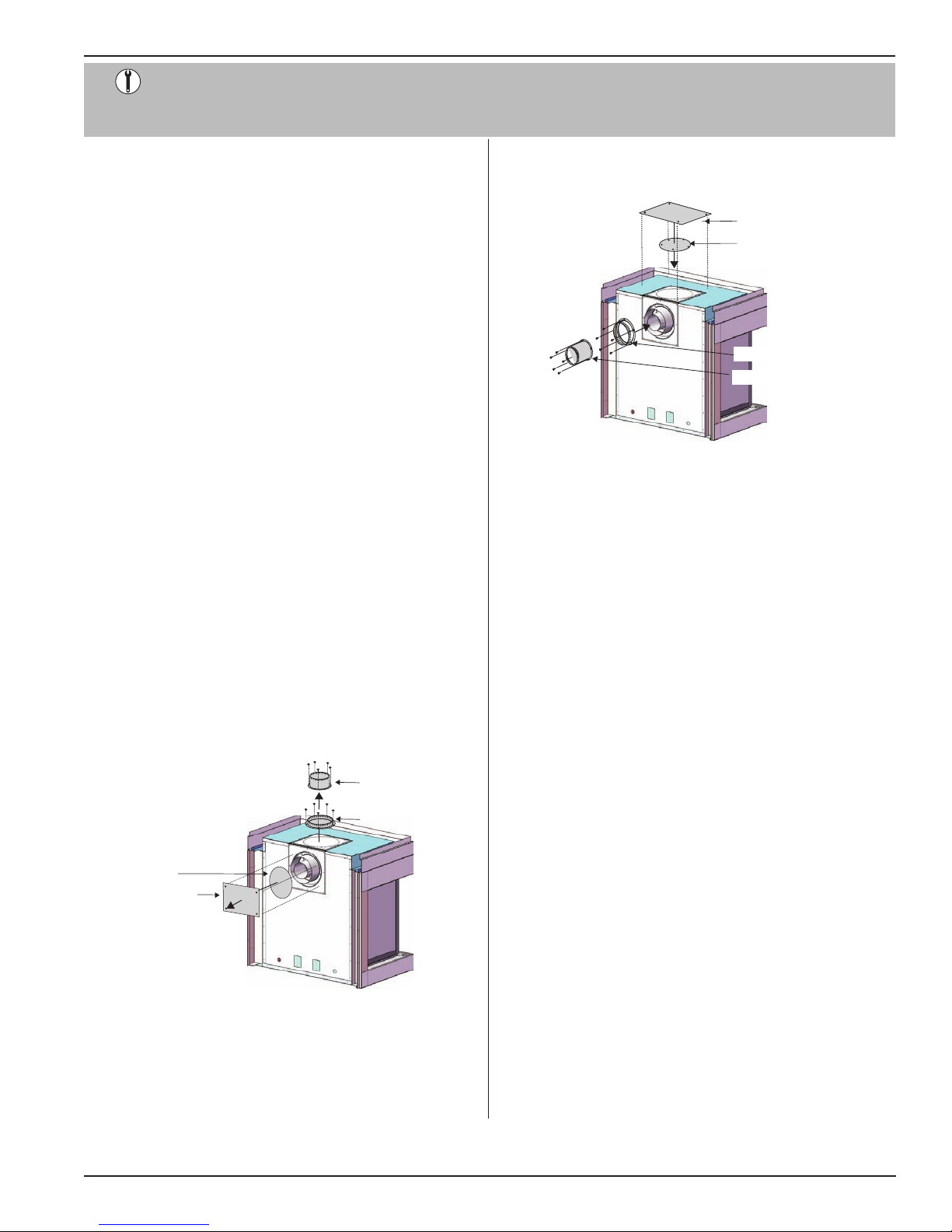
Section 3-1: CONVERTING TO TOP VENT / REAR VENT
4. Install the (5" and 8") collars to the rear vent outlet using the
included hardware, as illustrated Figure 8.
Flue Cover Plate
Flue Gasket
8” Outer Flue Collar
5” Inner Flue Collar
Figure 8. Flue cover and collar installation, Rear Vented replace.
Use the following instructions to convert an H*38PR* for Rear Vent use:
1. Remove the Rear ue cover and gasket (5" and 8") on the ue
outlet, as shown in Figure 7.
2. Next, Remove the Top ue collar's (5" and 8") on the ue outlet,
as shown in Figure 7.
3. Install the (removed) Rear ue cover and gasket material, to the
Top vent outlet. Fasten the cover with included hardware, as
illustrated Figure 8.
5” Inner Flue Collar
8” Outer Flue Collar
Flue Gasket
Flue Cover Plate
Figure 7. Flue cover and collar removal, Top Vented replace.
Part No. XG0211 - 080510
Page 7
H(L)38DF-PRC Indoor Panorama Gas Fireplace
3
Installation
Section 3-2: INSTALLING A ROOF MOUNTED DIRECT VENT
TERMINATION (PVTK-1)
This section applies to installations where the direct vent termination will be roof mounted.
Section 3-2-1: VENTING LAYOUT
Selection of components and details of venting lay out should
adhere to the following guidelines:
The maximum termination point is 32’ above the replace (NOTE:
if the maximum termination height is used, the ame pattern
may be affected).
The Vertical termination must be a minimum 2’ higher than where
the termination exits the roong materials, (asphault shingles,
cedar shakes, etc). This distance should be measured from the
high side of the roof slope where the ue ashing intersects the
roong materials. (see Figures 11 to 11c *).
Termination location must be a minimum 6’ from a mechanical
air inlet.
Termination location must be a minimum 18” from a parapet wall.
A maximum of two offsets (each offset is made up of 2-90°
bends) may be made.
Install a restop at any location where venting passes through
combustible materials and construction.
Utilize support straps, or support plates, and rings (as required)
to meet acceptable building practices.
Install all roof ashing and storm collars as shown.
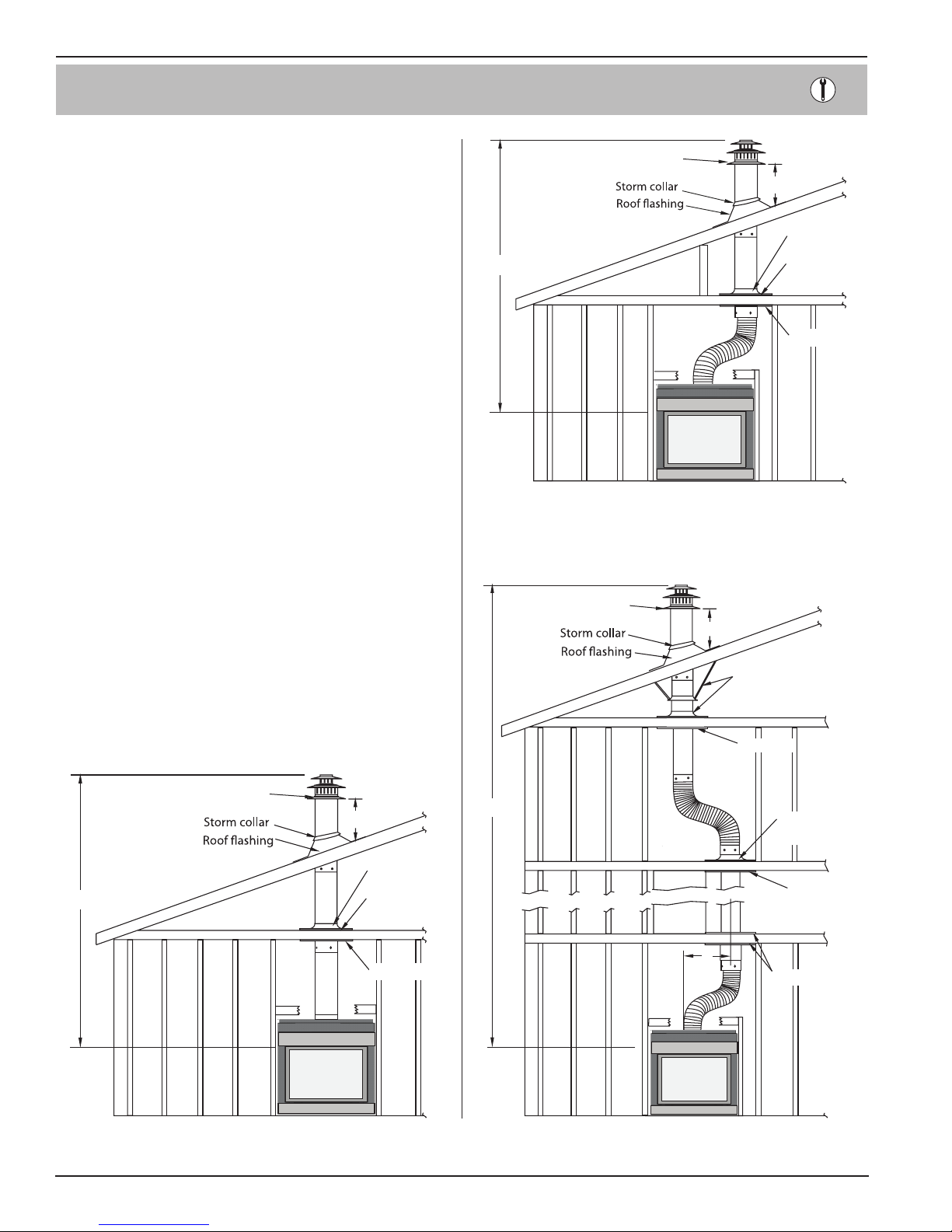
Roof mounted Terminations
The following details are some possible congurations for Roof
mounted terminations. See below.
PVTK1
Termination
2’ min.
Support ring
32’ max.
Obstacle
Support plate
Firestop
Figure 11a. Top vent, Roof mounted with 1 offset (1 offset= two 90°
bends).
PVTK1
Termination
2’ min.
Support straps or
support plate & ring
Firestop
PVTK1
Termination
32’ max.
Figure 11. Top vent, Roof mounted termination with no offset in
vent run.
Page 8
2’ min.
Support ring
Support plate
Firestop
2’ max
Figure 11b.
Support plate
& ring
Firestop
Obstacle
2’
Firestop
Top vent, Roof mounted with 2 offsets (1 offset= two 90°
bends).
Part No. XG0211 - 080510
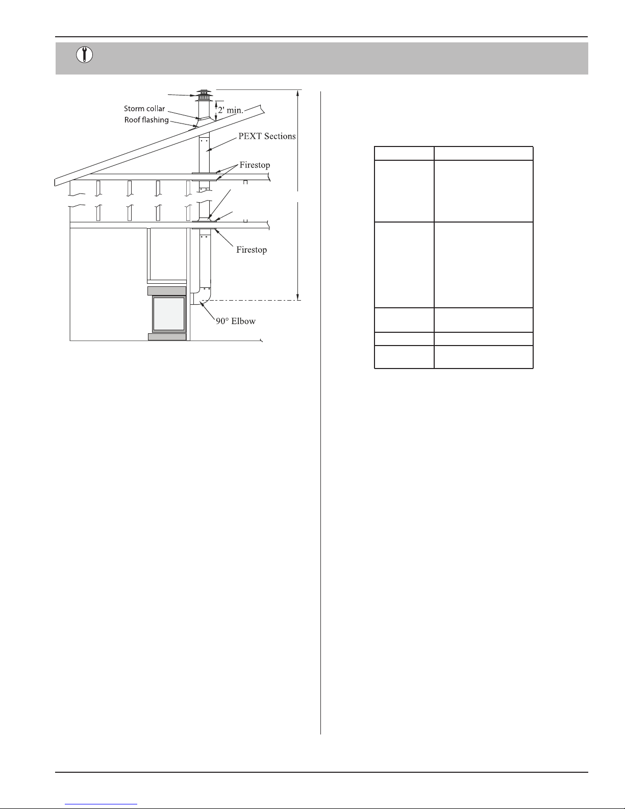
Installation
H(L)38DF-PRC Indoor Panorama Gas Fireplace
PVTK1
Termination
Support plate
Support ring
Figure 11c. Rear vent, Roof mounted venting (1 = 90° bend).
32’ max
Section 3-2-2: VENTING COMPONENTS
Select from the following components and associated Montigo
part numbers for installation of a Roof Mounted Termination.
Use only Montigo Vent Components. Use of non-Montigo parts
will void the warranty and may impede operation of the replace.
A- Termination PVTK-1
B - Flex Sections PFL- 1 (12" f/f Section)
C - Rigid Sections
D - Support Ring
& Plate
E - Firestop PS- 8
F - Roof Flashing PRF- 7 (1/12 - 7/12 pt.)
PFL- 18 (18" f/f Section)
PFL- 2 (24" f/f Section)
PFL- 3 (36" f/f Section)
PFL- 4 (48" f/f Section)
PFL- 6 (72" f/f Section)
PXT- 5 (5" f/f Section)
PXT-10 (10" f/f Section)
PEXT- 1 (12" m/f Section)
PXT- 20 (20" f/f Section)
PEXT- 2 (24" m/f Section)
PEXT- 3 (36" m/f Section)
PEXT- 4 (48" m/f Section)
PEXT- 6 (72" m/f Section)
PSPXT- 8
PRF-12 (7/12 - 12/12 pt.)
Connection and installation of the vent components should
adhere to the following guidelines:
Part No. XG0211 - 080510
Use any combination of rigid and Flex pipe as required.
Flex sections may be stretched up to 50% of their total length
(e.g. a 24” section maybe stretched to 36”).
Connect all vent sections using a minimum of three sheet
metal screws on the outer pipe ue.
Ensure the pipe ends male to female slide in a minimum of
1 1/2” of overlap.
Ensure all runs are supported with a minimum of 3 supports
per 10’ of venting.
When hanging/ supporting venting, ensure that 1” clearance
is maintained on sides and bottom of vent runs and 2” above
horizontal vent runs to any combustible material.
Ensure when cutting sections of rigid pipe to maintain integrity
of internal supports.
Place the springs, supplied with the pipe kit, between the
outer and inner pipes to keep the pipes separate and avoid
any possible hot spots.
Montigo recommends the use of a ex section for the nal pipe
connected directly to the replace offering greater exibility of
installation and absorption of movement.
When penetrating a combustible ceiling, a ceiling restop
must be used.
Montigo recommends that all exterior corners and joints be
sealed with exterior caulking however we encourage you to
consult your Building Envelope Engineer or Waterproong
Consultant for further recommendations.
Page 9
 Loading...