

Montigo H34DL User Manual
High voltage
Toxic
Flammable materials
Corrosive
Fork lift trucks
Danger overhead crane
Explosion risk
Blank
High voltage
Toxic
Flammable materials
Corrosive
Fork lift trucks
Danger overhead crane
Explosion risk
Blank
High voltage
Toxic
Flammable materials
Corrosive
Fork lift trucks
Danger overhead crane
Explosion risk
Blank
High voltage
Toxic
Flammable materials
Corrosive
Fork lift trucks
Danger overhead crane
Explosion risk
Blank
Installation & Maintenance Manual
H34DL
HC34DL (mobile home)
H38DL
H42DL
Indoor
DANGER
Read and understand this manual. Improper installation, adjustment, alteration,
service or maintenance can cause serious injury, property damage or even death.
For assistance or additional information consult a qualified installer, service
agency or the gas supplier.
CAUTION
Glass doors on gas fireplaces are extremely hot while the fireplace is on and
remain hot even after the fireplace has been turned off. Safety screens are
available and can reduce the risks of severe burns. Please keep children away
from the fireplace at all times.
Resi
dential
Gas Fireplace
WARNING
Do not store or use gasoline or any other flammable vapors and liquids in the vicinity of
this or any other gas burning appliance. A fire or explosion my occur causing serious
injury, property damage or even death.
NOTICE
Installer: Leave this manual with the appliance. Do not remove.
Consumer: Retain this manual for maintenance and future reference. Do not Discard.
DANGER
Do not try to light any appliance.
Do not touch any electrical switch; do not use any phone in your building.
®
Immediately call your gas supplier from a neighbor's phone. Follow the gas
supplier's instructions.
C US
If you cannot reach your gas supplier, call the fire department.
Canadian Heating Products Inc. Langley, BC V4W 4A1 | Montigo Del Ray Corp. Ferndale, WA 98248
IF YOU SMELL GAS
120611XG0140
H-Series DL Indoor Gas Fireplace
NOTICE
You must read and understand this manual prior to installation, operation or
troubleshooting this appliance. Please retain this owner’s manual for future reference
and maintenance.
Table of Contents
Safety Alert Key
Introduction ............................................................................... 3
Models............................................................................ 3
Installation
Before you Start ............................................................. 4
Installation Checklist ......................................................4
Section 1: Installation Overview and Product Dimensions ......5
Section 2: Framing the Fireplace .......................................... 6-7
Clearances ........................................................7
Installing the Standoffs & Nailing Flange ..........7
Section 3: The Direct Vent System ................................... 8 - 18
Section 3-1: Converting from Top Vent to Rear Vent ....8
Section 3-2: Installing a Roof mounted Termination 9 - 10
▪ Section 3-2-1: Venting Layout ......................................9
▪ Roof mounted Terminations
Standard Top Vent (no elbows or offsets)............. 9
Top Vent (two elbows one offset) ......................... 9
Top Vent (multi-elbows and offsets) ..................... 9
Standard Roof Vent (one elbows no offsets) ..... 10
Section 3-3: Installing a Wall mounted Termination . 11
▪ Standard PTO Installation .................................... 11
▪ Pre-installed MSR Frame .................................... 11
▪ Pre-installed BSR Frame ..................................... 11
▪ Installing MOSR Frame ....................................... 11
▪ Installing VSS Termination Shield ......................... 11
▪ Installing PTKOG Heat Guard .............................. 11
▪ Section 3-3-1: Venting Layout ................................... 12
▪ Top Vent, Wall mounted Graph, H34DL ................. 12
▪ Top Vent, Wall mounted Graph, H38DL ................. 12
▪ Top Vent, Wall mounted Graph, H42DL ................. 13
▪ Top Vent, Wall mounted termination (one elbow) ....13
▪ Top Vent, Wall mounted termination (multi elbow) ... 13
▪ Rear Vent, Wall mounted Graph, H34DL ............... 14
▪ Rear Vent, Wall mounted Graph, H38DL ............... 14
▪ Rear Vent, Wall mounted Graph, H42DL ............... 15
▪ Standard Rear Vent, (no elbows or offsets) ........... 15
▪
▪ Rear Vent, Wall mounted termination (45° corner) .. 16
▪ Rear Vent, Wall mounted termination (-45° corner) . 16
Page 2
Rear Vent, Wall mounted termination (two elbows) . 15
▪ Section 3-3-2: Venting Components .............................. 17
▪
▪
▪
Section 3-3-3: Heat Shields ......................................... 18
Installing a RHS7/8 Wall Mounted Heat Shield ....... 18
Installing a RHS100/101 Wall Mounted Heat Shield 18
Section 4: Wiring ................................................................... 19
▪
▪
▪
▪
▪ Installing HFK Fan Kit .........................................20
SIT - Nova 820 gas control and pilot ..................... 19
SIT - Proame gas control and pilot ..................... 19
Honeywell gas control and pilot ........................... 19
Installing Remote On/Off Wall Switch .................... 20
Section 5: Installing the Gas Line .......................................... 21
Section 5-1:
Section 5-2:
Section 5-3: Gas Connection......................................... 21
Fuel Conversion ........................................ 21
Gas Pressure ............................................ 21
Section 6: Finishing ............................................................... 22
Section 7: Installing and Removing the Door ........................ 23
Section 8: Installing the Accessories .............................. 24 - 27
▪ Installing the H34DL Log Set ...................................24
▪ Installing the HC34DLM Log Set ..............................25
▪ Installing the H38DL Log Set ...................................26
▪ Installing the H42DL Log Set ............................27 - 28
▪
Installing the Top / Bottom Horizontal Louvers ........... 28
Section 9: Operation ....................................................... 29 - 31
▪ Start-up Sequence with Continuous Pilot SIT Nova .... 29
▪ Start-up Sequence SIT Proame Gas valve............... 31
▪ Start-up Sequence with Honeywell Electronic Ignition 31
Maintenance .................................................................... 32 - 33
▪ General ................................................................. 32
▪ Cleaning ................................................................ 32
▪ Hi-Lo Burner Adjustment ......................................... 32
▪ Pilot Burner Adjustment ........................................... 32
▪ Troubleshooting ....................................................... 33
SIT- Nova 820 Gas Control Valve ......................... 33
SIT- Proame Gas Control Valve .......................... 33
▪
Appendix
A. Termination Locations .......................................... 35
Honeywell Gas Control Valve ............................... 33
Parts List ............................................................... 34
B. Warranty ............................................................ 36
C. State of Massachusetts. ......................................37
D. Mobile Home. ..................................................... 38
XG0140 - 070714
H-Series DL Indoor Gas Fireplace
High voltage
Toxic
Flammable materials
Corrosive
Fork lift trucks
Danger overhead crane
Explosion risk
Blank
Safety Alert Key
DANGER WARNING
Indicates a hazardous situation which, if not
avoided, WILL result in death or serious
injury or property damage.
CAUTION NOTICE
Indicates a hazardous situation which, if not
avoided, WILL result in minor or moderate
injury.
Introduction
INTRODUCTION
Congratulations on your purchase of a Montigo Fireplace.
With over 30 years of experience, Montigo is committed to providing
you with a gas replace that is not only a beautiful addition to your
space, but that is also designed and manufactured to the highest
safety, reliability and engineering standards.
We strongly encourage you to read and carefully follow the instructions
laid out in this Installation, Operation and Maintenance Manual
and retain it for your future reference. Pay special attention to all
cautions, warnings, and notices throughout this manual intended to
ensure your safety.
This manual covers installation, operation and maintenance. Lighting,
operation and care of this replace can be easily performed by the
homeowner. All installation and service work should be performed
by a qualied or licensed installer, plumber or gas tter as certied
by the state, province, region or governing body where the replace
is being installed.
WARNING
Hot glass will cause
burns. Do not touch
glass until unit is cooled.
Never allow children to
touch glass.
This installation, operation and maintenance manual is applicable
to the models described below. Refer to your rating plate to verify
included options. Throughout this manual instructions are applicable
to all models designated as H*DL*unless otherwise noted in the Table.
Warranty and Installation Information: (See Appendix B)
The Montigo warranty will be voided by, and Montigo disclaims any
responsibility for, the following actions:
XG140 - 070714
Indicates a hazardous situation which, if not
avoided, COULD result in death or serious
injury or property damage.
Address practices that are important, but
not related to personal injury
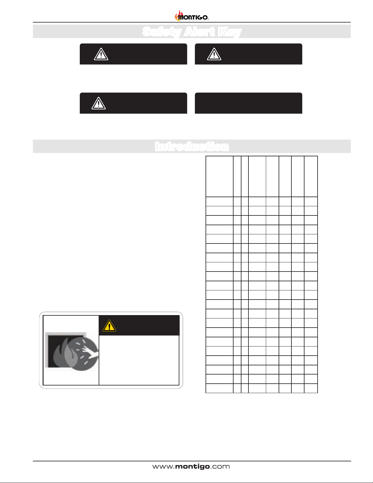
MODEL
H34DLN
H34DLN-I
H34DLN-F
HC34DLN-I
HC34DLL-I
HC34DLM
H34DLL
H34DLL-I
H34DLL-F
H38DLN
H38DLN-I
H38DLN-F
H38DLL
H38DLL-I
H38DLL-F
H42DLN
H42DLN-I
H42DLN-F
H42DLL
H42DLL-I
H42DLL-F
Natural Gas
Liquid Propane
Gas Rating
(BTU hr)
Traditional Burner
w/ Logset
Standing Pilot
Ignition
Honeywell Hot
Surface Ignition
X 18,000 X X
X 18,000 X X
X 18,000 X X
X 22,000 X X
X 22,000 X X
X X 22,000 X X
X 18,000 X X
X 18,000 X X
X 18,000 X X
X 26,000 X X
X 26,000 X X
X 26,000 X X
X 26,000 X X
X 26,000 X X
X 26,000 X X
X 34,000 X X
X 34,000 X X
X 34,000 X X
X 32,000 X X
X 32,000 X X
X 32,000 X X
SIT Electronic
Ignition
► Modication of the replace and/or components including Direct-
Vent assembly or glass doors.
► Use of any component part not manufactured or approved
by Montigo in combination with this Montigo replace system.
► Installation other than as instructed in this manual.
Consult your local Gas Inspection Branch on installation requirements
for factory-built gas replaces. Installation & repairs should be done by
a qualied contractor.
Page 3
H-Series DL Indoor Gas Fireplace
Installation and repairs should be done by an authorized gas fireplace service technician.
The appliance should be inspected before use and at least annually by a professional. More
frequent cleaning may be required due to excessive lint from carpeting, bedding material,
etc. It is imperative that control compartments, burners and circulating air passageways of
the fireplace are kept clean.
NOTICE
surfaces.
Installation
IMPORTANT MESSAGE: SAVE THESE INSTRUCTIONS
The H*DL* Direct Vent replace must be installed in accordance
with these Instructions. Carefully read all the Instructions in this
manual rst. Consult the Local Gas Branch to determine the need
for a permit prior to starting the installation. It is the responsibility
of the installer to ensure this replace is installed in compliance
with the manufacturers instructions and all applicable codes.
BEFORE YOU START:
CAUTION
Due to high operating temperatures, this appliance should be located out of traffic &
away from furniture and draperies.
Children and adults should be alerted to the hazards of the high surface temperature,
which could cause burns or clothing ignition.
Young children should be carefully supervised when they are in the same room as the
appliance.
Clothing or other flammable materials should not be placed on or near the appliance.
DANGER
Installation Checklist
Determine the desired install location of your replace.
See Section 1, Dimensions on Page 5, and refer to the Framing
Section 2 for details.
Select the location of your termination and resulting vent run.
Your selected termination location must be the highest point
in the Direct Vent installation.
Should it be impossible to meet the venting requirements laid out
in Section 3: Venting, please contact your local Montigo dealer
regarding the use of a Montigo Power Vent.
Lay out the Vent run; calculating the required elbows and
straight runs of 4"/7" for H*34DL or 5"/8" for H38DL & H42DL
flex or rigid pipe.
Layout Electrical Requirements Refer to Section 4: Wiring, for
Details.
Refer to Section 5: Installing the Gas Line, for details on the
gas connection and access.
Refer to local codes and guidelines for installation requirements.
Installation and repairs should be done by a qualied
contractor and must conform to:
• Installations in Canada must conform to the local codes or in the
absence of local codes to the current version of Natural Gas and Propane
Installation Code, CSA B149. Electrical Installations must conform to
the local codes or, in the absence of local codes, to the current version
of Canadian Electrical Code, CSA C22.1.1
• Installations in the USA must conform to the local codes or in
the absence of local codes to the current version of National Fuel Gas
Code, ANSI Z223.1/NFPA 54. Electrical Installations must conform to
the local codes or, in the absence of local codes, to the current version
of the National Electrical Code, ANSI/NFPA 70. See Appendix C for
installation within the State of Massachusetts.
When this appliance is installed directly on any combustible material other than wood
flooring, it must be installed on a metal or wood panel extending the full width and
depth of the appliance or a fire will occur causing serious injury, property damage or
even death.
CAUTION
Young children should be carefully supervised when they are
in the same room as the applicance. Toddlers, young children
and others may be susceptible to accidental contact burns. A
physical barrier is recommended if there are at risk individuals
in the house. To restrict access to a fireplace or stove, install
an adjustable safety gate to keep toddles, young children and
other at risk individuals out of the room and away from hot
surfaces.
Page 4
CAUTION
Young children should be carefully supervised when they are
in the same room as the applicance. Toddlers, young children
and others may be susceptible to accidental contact burns. A
physical barrier is recommended if there are at risk individuals
in the house. To restrict access to a fireplace or stove, install
an adjustable safety gate to keep toddles, young children and
other at risk individuals out of the room and away from hot
XG0140 - 070714
Installation
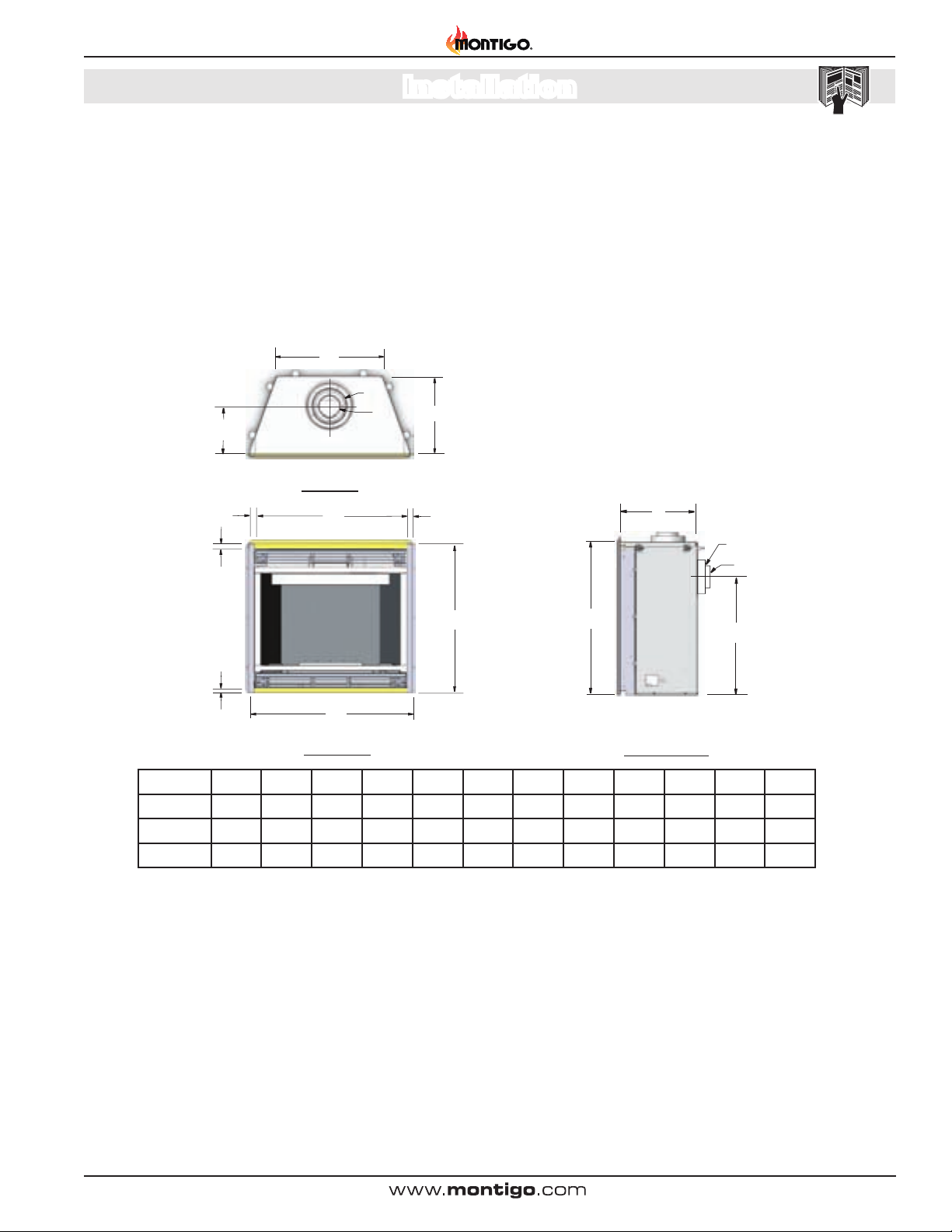
Section 1: Installation Overview and Product Dimensions
H-Series DL Gas Fireplace
Please review the Installation Checklist on Page 4 for general information
on preparing for a successful installation of your replace.
The H*DL* replace may be installed in any location that maintains proper
clearances to air conditioning ducts, electrical wiring and plumbing.
The replace dimensions are shown below:
H
K
I
J
C
C
L
J
L
K
G
Top View
D
D
C
D
Safety, as well as efciency of operation, should be considered when
selecting the replace location. Select a location that does not interfere
with room trafc, has adequate ventilation and offers an accessible path
for Direct Vent installation.
G
K
J
B
F
A
Front View
B
L
LH-Side View
A B C D E F G H I J K L
7
H*34DL* 33
/8 31 1/2 31 3/8 1 1/4 21 1/2 1 15 1/4 21 3/4 7 3/4 4 7 25
H38DL* 37 3/4 34 1/2 34 1/4 1 1/4 24 1/2 1 16 1/4 25 9 1/4 5 8 27 3/4
H42DL* 42 1/4 38 1/2 39 3/4 1 1/4 28 1/2 1 17 3/4 28 1/4 10 3/8 5 8 31 1/2
Figure 1. Fireplace dimensions (Tolerance ± ⅛").
XG0140 - 070714
Page 5
H-Series DL Indoor Gas Fireplace
.
Installation
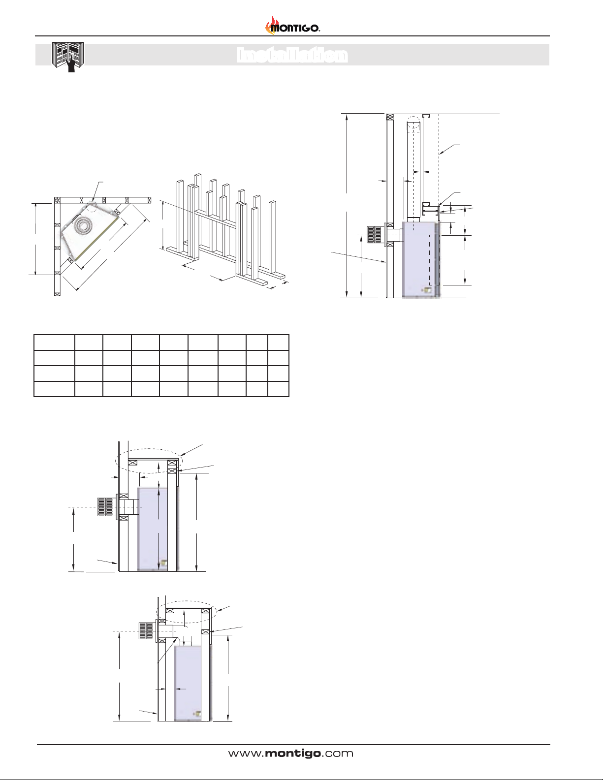
Section 2: Framing
1). Frame in the enclosure for the unit with framing materials. The
framed opening for the assembled replaces are as shown below,
see Figure 2
.
Top Vent
Ceiling level
NOTE: When constructing the framed opening, please ensure there is
access to install the gas line when the unit is installed. See Figure 26.
0" clearance
to corners only
M”
Q”
N”
P”
N”
(When sheetrock is not used behind
the replace, framing depth "O" may be
reduced by 5/8".)
L M N O P Q S T
H*34DL* 25
H38DL* 27 3/4
H42DL* 31 1/2
Figure 2. Framing dimensions for Straight wall and Corner Installation.
37 1/4 33 3/4 17 7/8 52 3/8 37 31 41
40 1/4 37 3/4 18 7/8 57 1/2 40 5/8 34 44
44 1/4 42 19 3/8 63 3/4 45 1/8 38 48
Non-Combustible
materials. Alcove
2”
Min 1”
Rear
Vent
Exterior
Wall
Min.
96”
min.
18”
max.
L
O”
over fireplace.
Non-combustible
header
Non-combustible
Facing materials
3”
12”
door
opening
Floor
Figure 5. Non Combustible Framing for Top Vent or Rear Vent, with Alcove
ABOVE FIREPLACE.
Combustible
Shelf
min.
2”
18”
max.
9”
S
Combustible
Header
M
L
Exterior
Wall
Figure 3. Combustible Framing for shelves over the replace, Rear vent.
Combustible
Shelf
Combustible
Header
M
† See Vent Graph for
minimum measurement
requirements gures
11, 12 or 13.
†
PEL Shor t
90° elbow
L
2” min.
Exterior
Wall
17 1/2”
Figure 4. Combustible Framing for shelves over the replace, Top vent.
Page 6
XG0140 - 070714
Installation
H-Series DL Gas Fireplace
Clearances
When installing a shelf over the top of the replaces, the following
guidelines must be adhered to:
Rear Vent applications, the minimum clearance is 2" from the rear of
the replace to a wall, or any combustible materials, and 9" clearance
from the top of the replace to the underside of any combustible shelf
materials.
Top Vent applications, the minimum clearance is 2" from the rear of
the replace to a wall, or any combustible materials, and 17 1/2" to the
underside of any combustible shelf materials, Figure 4.
Top or Rear Vent applications where the Minimum mantel height is
required above the replace, (for an alcove or low prole shelf), ALL
Materials MUST BE NON-COMBUSTIBLE, Figure 5. The minimum
clearance is 2" from the rear of the replace to a wall, or any combustible
materials.
1” clearance is maintained on sides and bottom of vent runs and 2”
above horizontal vent runs to any combustible material.
The replace clearances are shown below:
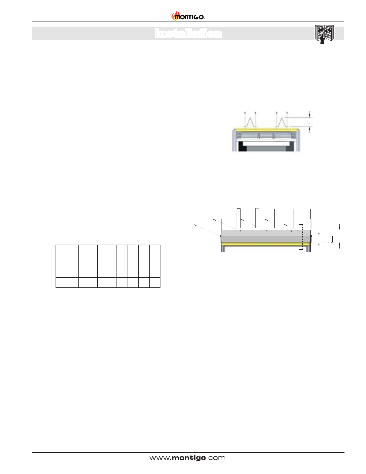
Installing The Standoffs
To avoid elevated mantel temperatures, all H*DL*- Series gas
replaces are required to have the supplied standoffs installed.
The replace is supplied with two standoffs. Bend and install these
standoffs on top of the replace ensuring that the height of the standoff
maintains a 6" clearance.
6"
Figure 6. Installing the standoff's.
Installing the Nailing Flange Extension - HC34DL* Only
Once the replace is placed into the rough framed opening, the supplied
nailing ange extension (Part No. HC34074) must be fasten securely
into place, with nails or wood screws. as shown in Figure 7.
3”
6”
MODEL
H*DL* 9 17 1/2 2 1 0 4
† Note: Clearance from top of replace to a combustible ceiling within
the replace enclosure.
Top -
Rear Vent †
Top -
Top Vent †
Rear
Sides
Floor
Mantel
Front View Side View
Figure 6a. Installing the Nailing Flange Extension.
The supplied nailing ange extension must be placed along the top
edge of the replace and securely fastened in place to the combustible
wood framing.
Note: The nailing ange extension can be substituted with a piece of
NON-Combustible material of the same size and thermal characteristics,
ie: cement board or equivalent. This is recommended in applications
where the facing materials will not adhere to the metal nailing ange.
XG0140 - 070714
Page 7
H-Series DL Indoor Gas Fireplace
Section 3: Venting
Installation
Montigo supplies a variety of direct venting and termination options.
The direct vent termination location MUST be selected such that
it is the highest point in the venting assembly. It should also be
selected such that it provides the shortest vent run possible. Should
it be impossible to ensure that the termination is the highest point
or to meet the venting guidelines laid out below please contact your
Montigo dealer to discuss power venting options.
NOTES FOR PLANNING VENTING:
H*34DL* replace is certied for use with Montigo 4"/7"
venting components.
H38DL* and H42DL* replaces are certied for use with
5"/8" venting components.
Venting originates from the unit through the top or through
the rear.
Venting can terminate through the roof or through an
exterior wall.
Refer to Appendix A - Termination Locations to ensure the
planned termination location is acceptable.
Once the termination location has been established, refer
to the appropriate section below for installation details
All replaces shipped from the factory are Top vent.
.
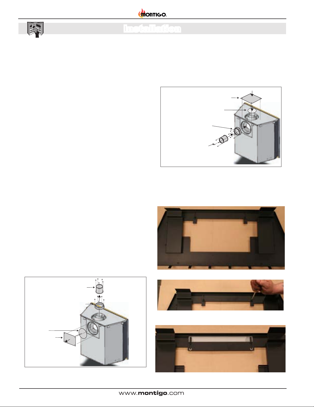
Section 3-1: CONVERTING TO REAR VENT
3. Install the (removed) Rear ue cover and gasket material, to the
Top vent outlet. Fasten the cover with included hardware, as
illustrated Figure 7a.
4. Install the (4/5" and 7/8") collars to the rear vent outlet using the
included hardware, as illustrated Figure 7a.
Flue Cover Plate
Flue Gasket
7” Outer Flue Collar, H*34DL*
8” Outer Flue Collar, H38DL & H42DL
4” Inner Flue Collar, H*34DL*
5” Inner Flue Collar, H38DL & H42DL
Figure 7a. Flue cover and collar installation, Rear Vented replace.
Section 3-1-2: AIR BAFFLE for H38DL* ONLY
NOTE: Air Bafe is shipped open. If you are top venting, the air bafe
should be closed following these steps:
NOTE: H42DLL* Propane models MUST be installed in a top vent
application ONLY.
Use the following instructions to convert an H*DL* for Rear Vent use:
1. Remove the Rear ue cover and gasket (4/5" and 7/8") on the
ue outlet, as shown in Figure 7.
2. Next, Remove the Top ue collar's (4/5" and 7/8") on the ue
outlet, as shown in Figure 7.
4” Inner Flue Collar, H*34DL*
5” Inner Flue Collar, H38DL & H42DL
7” Outer Flue Collar, H*34DL*
8” Outer Flue Collar, H38DL & H42DL
Flue Gasket
Flue Cover Plate
Figure 7. Flue cover and collar removal, Top Vented replace.
Figure 7b. Air Bafe in Open position
Figure 7c. Pull the air bafe forward as far as possible and screw the air bafe
closed.
Figure 7d. Air bafe in closed position
Page 8
XG0140 - 070714
Installation
3
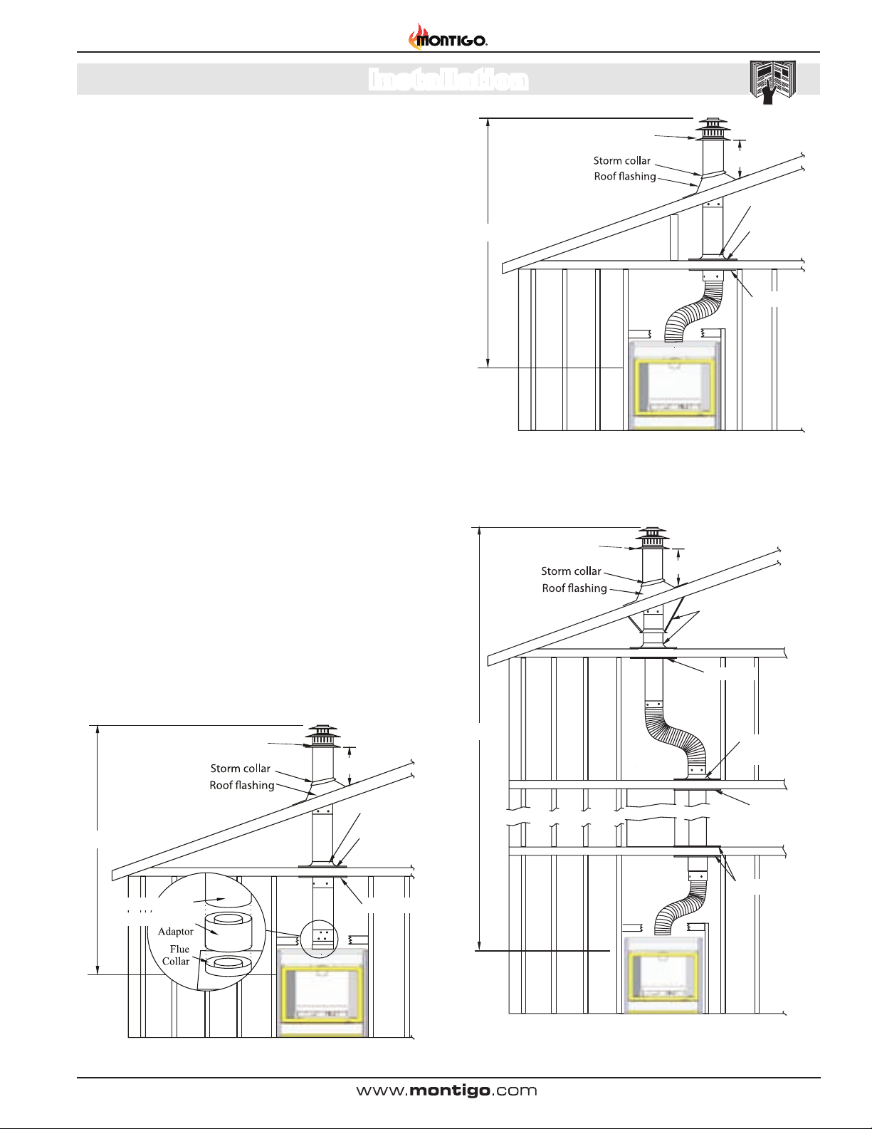
Section 3-2: INSTALLING A ROOF MOUNTED DIRECT VENT
TERMINATION (MVTK-1SS / PVTK-1SS)
This section applies to installations where the direct vent
termination will be roof mounted.
Section 3-2-1: VENTING LAYOUT
Selection of components and details of venting lay out should
adhere to the following guidelines:
32’ max.
PVTK1
MVTK-1 / PVTK-1
Termination
Termination
Obstacle
H-Series DL Gas Fireplace
2’ min.
Support ring
Support plate
The maximum termination point is 32’ above the replace (NOTE:
if the maximum termination height is used, the ame pattern
may be affected).
The Vertical termination must be a minimum 2’ higher than where
the termination exits the roong materials, (asphalt shingles,
cedar shakes, etc). This distance should be measured from the
high side of the roof slope where the ue ashing intersects the
roong materials. (see Figures 8 to 8c).
Termination location must be a minimum 6’ from a mechanical
air inlet.
Termination location must be a minimum 18” from a parapet wall.
For a more detailed diagram of allowed termination locations,
see Appendix A.
A maximum of two offsets (each offset is made up of 2-90°
bends) may be made.
Firestops must be installed as required by national & local codes.
Ensure all horizontal runs are supported with a minimum of 3
supports per 10’ of venting.
Install all roof ashing and storm collars as shown.
Roof mounted Terminations
The following details are some possible congurations for Roof
mounted terminations. See below.
Firestop
Figure 8a. Top vent, Roof mounted with 1 offset (1 offset= two 90° bends).
MVTK-1 / PVTK-1
PVTK1
Termination
Termination
2’ min.
Support straps or
support plate & ring
Firestop
MVTK-1 / PVTK-1
PVTK1
Termination
Termination
2’ min.
Support ring
32’ max.
MEXT/PEXT
MXT-10/PXT-10
Figure 8. Top vent, Roof mounted termination with no offset in vent run.
Support plate
Firestop
XG0140 - 070714
2’ max
Obstacle
Figure 8b. Top vent, Roof mounted with 2 offsets (1 offset= two 90° bends).
Support plate
& ring
Firestop
Firestop
Page 9
H-Series DL Indoor Gas Fireplace
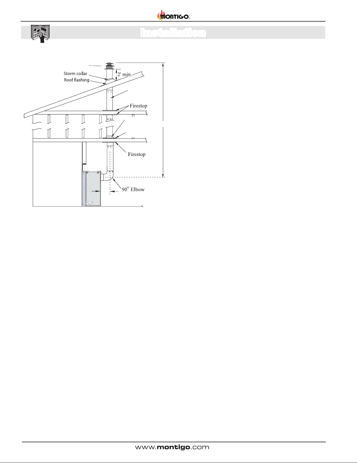
P
MVTK-1 / PVTK-1
VTK1
Termination
Termination
Installation
MEXT/PEXT
Sections
Support plate
Support ring
18”
Max.
Figure 8c. Rear vent, Roof mounted venting (1 = 90° bend).
32’ max
Page 10
XG0140 - 070714
Installation
H-Series DL Gas Fireplace
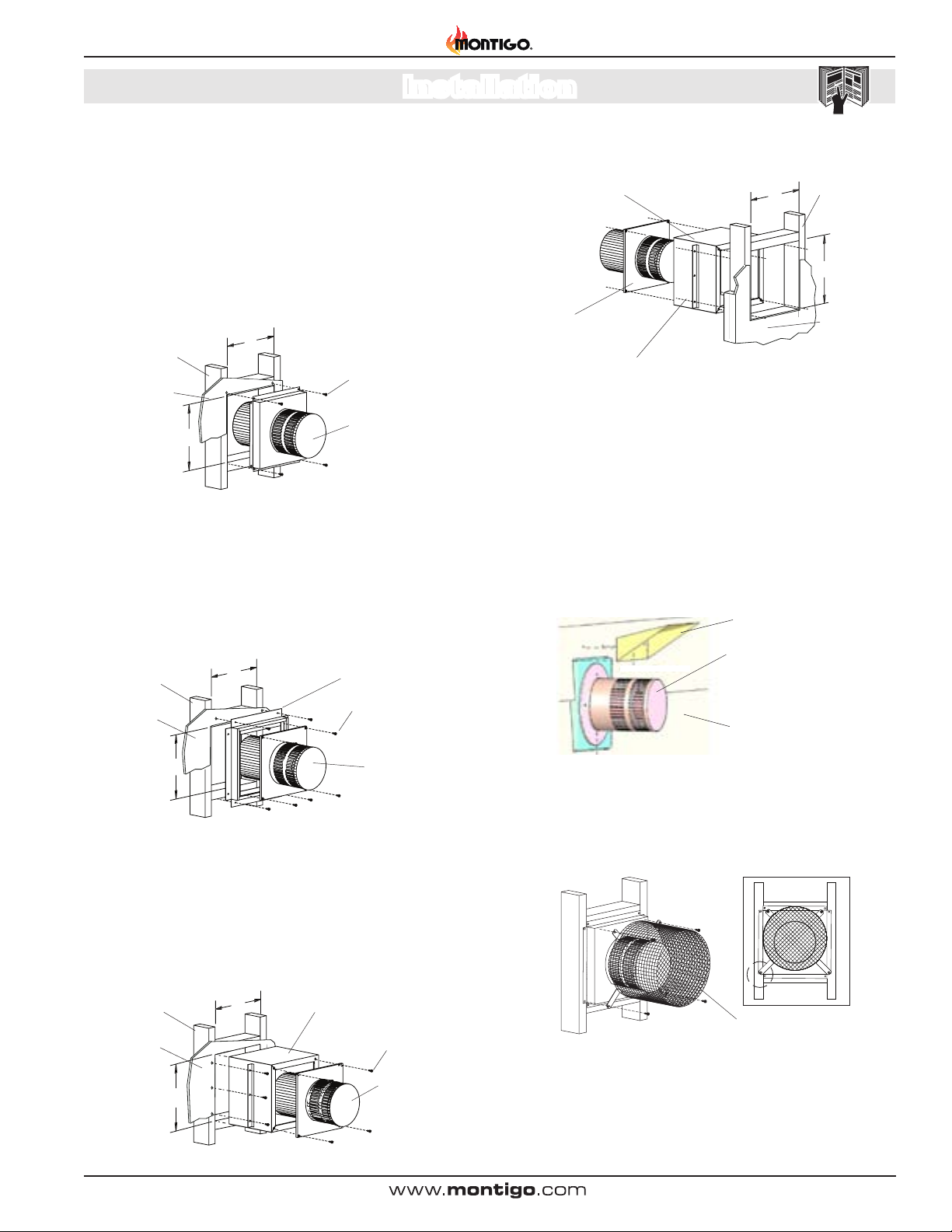
Section 3-3: INSTALLING A WALL MOUNTED DIRECT VENT
TERMINATION
This section applies to installations where the direct vent termination will be wall mounted.
1). Installation of Termination with built in frame
A Termination with a Built-In Frame is installed during framing of a structure.
1. Frame the termination opening to 11" x 11".
2. Install exterior sheathing to the structure framing.
3. Fasten the termination to the sheathing using a minimum of 4 screws.
11”
Framing
Exterior
Sheathing
1”
Figure 9. Installing a PTO-F termination.
Fastening Hardware,
minimum 4-screws
PTO-4F (5"/8")
Termination
2). Installation of termination frame at time of framing
Terminations with a MSR frame allow the installation of the frame prior
to installation of the termination.
1. Frame the termination opening to 12" x 12".
2. Secure the MSR Frame to the exterior sheathing of the structure.
3. Fasten the termination to the MSR Frame using a minimum of 4 screws.
2”
Framing
1
MSR Frame
4). Installation of termination from inside structure
A Termination with a MOSR Frame is installed from the inside of the
structure. These are commonly used in high-rise construction.
MOSR Frame
PTO-4 (5"/8")
Termination
Fastening Hardware,
minimum 4-screws
Figure 9c. Installing a PTO termination with the MOSR frame.
12”
Framing, concrete or other
materials
12”
Exterior Sheathing, concrete or
other materials
1. Frame the MOSR opening to 12" x 12".
2. Fasten the MOSR frame to the interior side of the studs, concrete,
or nished wall construction using a minimum of 4 screws.
3. Insert the termination into the MOSR frame as shown here, (from
the inside) and attach to the MOSR by installing a min. quantity of
4 bolts into the threaded nuts on the MOSR Frame.
5). Installation of a termination shield for Vinyl Siding
The VSS Termination shield is installed when the exterior of a structure
is clad with Vinyl siding. It is placed directly above, and on centre with
the termination.
VSS Vinyl shield
PTO-4 (5"/8")
Termination
Exterior
Sheathing
12”
Figure 9a. Installing a PTO termination with the MSR frame.
Fastening Hardware,
minimum 4-screws
PTO-4 (5"/8")
Termination
3). Installation of termination frame at time of framing in
Masonry
Terminations with a BSR frame allow the installation of the frame in
masonry prior to the installation of the termination
1. Frame the BSR opening to 12" x 12".
2. Secure the BSR Frame to the exterior sheathing of the structure.
3. Fasten the termination to the BSR Frame using a minimum of 4 screws.
2”
Framing
Exterior
Sheathing
12”
Figure 9b. Installing a PTO termination with the BSR frame.
1
XG0140 - 070714
BSR Frame
Fastening Hardware,
minimum 4-screws
PTO-4 (5"/8")
Termination
Exterior Vinyl
siding
Figure 9d. Installing the VSS Vinyl Shield.
Installing Heat Guards over Terminations is recommended
in installations where the termination is located within 7' feet above
grade, or above a pedestrian walkway, and may be Required by code
in Public areas.
PTKOG (5"/8")
Figure 10. Installing a PTO termination heat guard.
1. Ensure that the two long mounting brackets are facing the bottom
of the termination. (See inset). This will provide more heat protection
at the top of the termination, where temperatures are highest.
2. Attach to the faceplate of the termination using four sheet metal
screws.
Page 11
H-Series DL Indoor Gas Fireplace
Installation
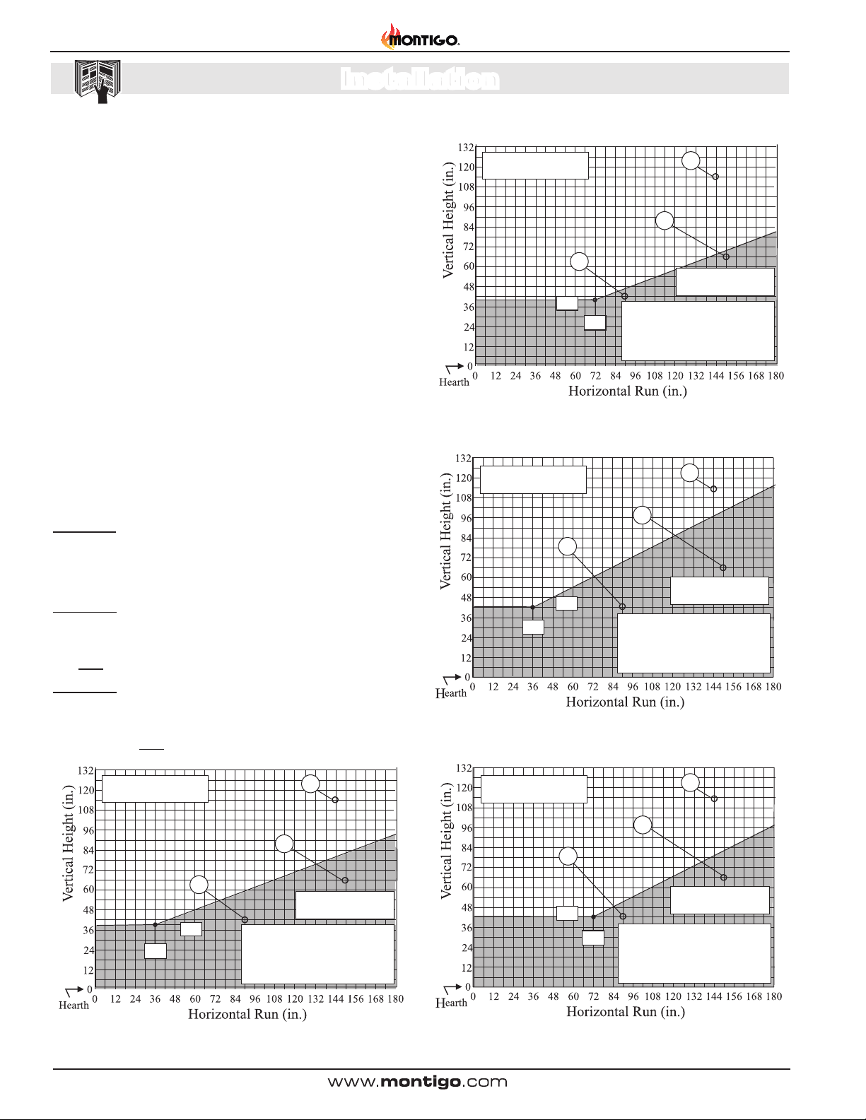
Section 3-3-1: VENTING LAYOUT: Wall mounted termination.
Selection of components and details of venting layout should
adhere to the following guidelines:
Vent terminations must not be recessed in walls or siding.
For Heat Shield Requirements see Section 3-3-3.
Once the proposed venting layout has been determined, refer to
Figure 11, 11a, 12, 12a, 13, 15, 16, or 17 to ensure the layout
is acceptable.
Notes Wall Mounted Terminations: TOP VENT
All measurements for vertical or horizontal runs are measured
from center of the vent pipe.
Venting runs must fall within the limits set by the venting graphs,
Figure 11, 11a, 12, 12a or 13.
The Venting Graph:
Measure the vertical height from the replace hearth to the centre of
the termination and the horizontal run from the replace ue collar to
the wall ange of the termination. Plot on the Venting Graph Figure 11,
11a, 12, 12a or 13 with an 'X'.
If the 'X' falls on or above the top boundary of the shaded area, the
installation is acceptable.
Example A: (Acceptable Installation)
If the vertical dimension from the hearth is 114" and the horizontal
run to the wall ange of the vent termination is 144", this would be
an acceptable installation.
Example B: (Unacceptable Installation)
If the vertical dimension from the hearth is 42" and the horizontal
run to the wall ange of the vent termination is 90", this would
NOT be an acceptable installation.
Example C: (Unacceptable Installation)
If the vertical dimension from the oor of the replace is 66" and
the horizontal run to the wall ange of the vent termination is 150",
this would NOT be an acceptable installation.
Acceptable vent run
within non-shaded area.
38”
B
If your installation does not fall
72
”
within the venting graph parameters,
please contact a local Montigo
dealer for Power Venting options.
A
C
Unacceptable vent run
within shaded area.
Figure 11a H*34DLN* Top Vent Venting Graph for wall mounted terminations,
See Figures 14, 14a, or 14b.
Acceptable vent run
within non-shaded area.
B
42”
36
”
C
If your installation does not fall
within the venting graph parameters,
please contact a local Montigo
dealer for Power Venting options.
A
Unacceptable vent run
within shaded area.
Figure 12 H38DLL* Top Vent Venting Graph for wall mounted terminations,
See Figures 14, 14a, or 14b.
Acceptable vent run
within non-shaded area.
38”
36
”
B
If your installation does not fall
within the venting graph parameters,
please contact a local Montigo
dealer for Power Venting options.
A
C
Unacceptable vent run
within shaded area.
Figure 11 H*34DLL* Top Vent Venting Graph for wall mounted terminations,
See Figures 14, 14a, or 14b.
Page 12
Acceptable vent run
within non-shaded area.
B
42”
C
If your installation does not fall
72
”
within the venting graph parameters,
please contact a local Montigo
dealer for Power Venting options.
A
Unacceptable vent run
within shaded area.
Figure 12a H38DLN* Top Vent Venting Graph for wall mounted terminations,
See Figures 14, 14a, or 14b.
XG0140 - 070714
 Loading...