

Montigo H34BF, H38BF, H42BF Operation Manual
Installation
®
C US
Operation &
Maintenance
H-Series BF
Gas Fireplace
H34BF
H38BF
H42BF
Warning:
Improper installation, adjustment,
alteration, service or maintenance can
cause injury or property damage. Refer to
this manual. For assistance or additional
information consult a qualied installer,
service agency or the gas supplier.
For Your Safety:
Do not store or use gasoline
or other ammable vapors
and liquids in the vicinity
of this or any other
appliance.
What To Do If You Smell Gas:
• Do not try to light any appliance.
• Do not touch any electrical switch; do not use any phone in your building.
• Immediately call your gas supplier from a neighbor's phone. Follow the gas
supplier's instructions.
• If you cannot reach your gas supplier, call the re department.
Safety Notice:
Glass doors on gas replaces are
extremely hot while the replaces is on
and remain hot even after the replace
has been turned off. Safety screens
are available and can reduce the risks
of severe burns. Please keep children
away from the replace at all times.
■ Check local co d e s and
read all instructions prior to
installation.
■ Leave this manual with the
owner.
H-Series BF Gas Fireplace
Table Of Contents Introduction
Introduction .............................................................................. 2
Installation
Installing and Framing the Fireplace .............................. 3
Installing the Gasline ...................................................... 4
The Remote Switch ........................................................
Direct Vent Installation ................................................... 4
General Venting Requirements .........................4
Terminations ......................................................
Converting to Top or Rear Vent model .............. 5
Venting for Top Vent models ..............................
Venting for Rear Vent models ............................ 9
Construction around the replace
Facing .............................................................. 11
Mantels and Surrounds ................................... 11
Wiring ......................................................................... 11
Installing Optional Fans................................................ 11
Removing and Installing the Door ................................ 12
Installing the Logset ..................................................... 13
Installing the Horizontal Trim ........................................ 13
Operation ......................................................................... 14 - 16
Maintenance ....................................................................16 - 17
Warranty ................................................................................. 18
Appendix
A. Termination Locations .............................................. 19
Thank You for choosing a Montigo Gas Fireplace.
About this Fireplace:
The H-Series BF is a replace with a pan-style burner and glowing
embers. This replace is available in two models.
The H34BF is rated for Natural Gas at 18,000 BTU/H (5.28 Kilowatts)
4
5
6
Input or Propane at 18,000 BTU/H (5.28 Kilowatts) Input.
H34BF; Top Vent, Millivolt Pilot.
■
H34BF-I; Top Vent, Intermittent Pilot (HSI).
■
H34BF-A; Top Vent, Electronic Ignition (American Flame).
■
The H38BF is rated for Natural Gas at 26,000 BTU/H (7.62 Kilowatts)
Input or Propane at 26,000 BTU/H (7.62 Kilowatts) Input.
H38BF; Top Vent, Millivolt Pilot.
■
H38BF-I; Top Vent, Intermittent Pilot (HSI).
■
H38BF-A; Top Vent, Electronic Ignition (American Flame).
■
The H42BF is rated for Natural Gas at 34,000 BTU/H (9.97 Kilowatts)
Input or Propane at 28,000 BTU/H (9.97 Kilowatts) Input.
H42BF; Top Vent, Millivolt Pilot.
■
H42BF-I; Top Vent, Intermittent Pilot (HSI).
■
H42BF-A; Top Vent, Electronic Ignition (American Flame).
■
How to use this manual:
This manual covers installation, operation and maintenance. Lighting,
operation and care of this replace can be easily performed by the
homeowner. However, all installation and service work should be
performed by a qualied or licensed installer, plumber, or gastter who
is qualied or licensed by the state, province, region, or governing body
in which the appliance is being installed.
This manual covers all models and unless otherwise specied, the
designation H-Series BF refers to all models. Sections which are
specic to a particular model are marked with a symbol, plus
the appropriate model number.
CAUTIONS
Due to its high operating temperatures, the appliance
should be located out of trafc & away from furniture
and draperies.
Children and adults should be alerted to the hazards
■
of the high surface temperature, which could cause
burns or clothing ignition.
Young children should be carefully supervised when
■
they are in the same room as the appliance.
Clothing or other ammable materials should not
■
be placed on or near the appliance.
Page 2
Warranty and Installation Information:
The Montigo warranty will be voided by, and Montigo disclaims any
responsibility for, the following actions:
Modication of the replace and/or components including Direct-Vent
■
assembly or glass doors.
Use of any component part not manufactured or approved by Montigo in
■
combination with this Montigo replace system.
Installation other than as instructed in this manual.
■
Consult your local Gas Inspection Branch on installation requirements
for factory-built gas replaces. Installation & repairs should be done by
a qualied contractor.
Installations in Canada must conform to the current CAN/CGA B-
149.1 and .2 Gas Installation Code and local regulations. If the optional
air-circulating fan kit is installed, it must be electrically grounded in
accordance with CSA C22.1 Canadian Electrical Code Part 1 and/or
Local Codes.
Installations in the USA must conform to local codes, or in the absence
of local codes to the National Fuel Gas Code, ANSI Z223.1-1988. If the
optional air-circulating fan is installed, it must be grounded in accordance
with local codes or, in the absence of local codes, with the National
Electrical Code, ANSI/NFPA 70-1987.
Part No. XG0145
Installation
R
R
N
P
Q
0" clearance
to corners only
M
N
O
N
P
Q
0" clearance
to corners only
R
R
H-Series BF Gas Fireplace
Installing The Fireplace Shell
The replace may be installed in any location that maintains proper clearances to air conditioning ducts, electrical wiring and plumbing. Safety,
as well as efciency of operation, must be considered when selecting
the replace location. Try to select a location that does not interfere
with room trafc, has adequate ventilation, and offers an accessible
pathway for Direct Vent installation. Refer to page 4 - Vent Installation
for more information.
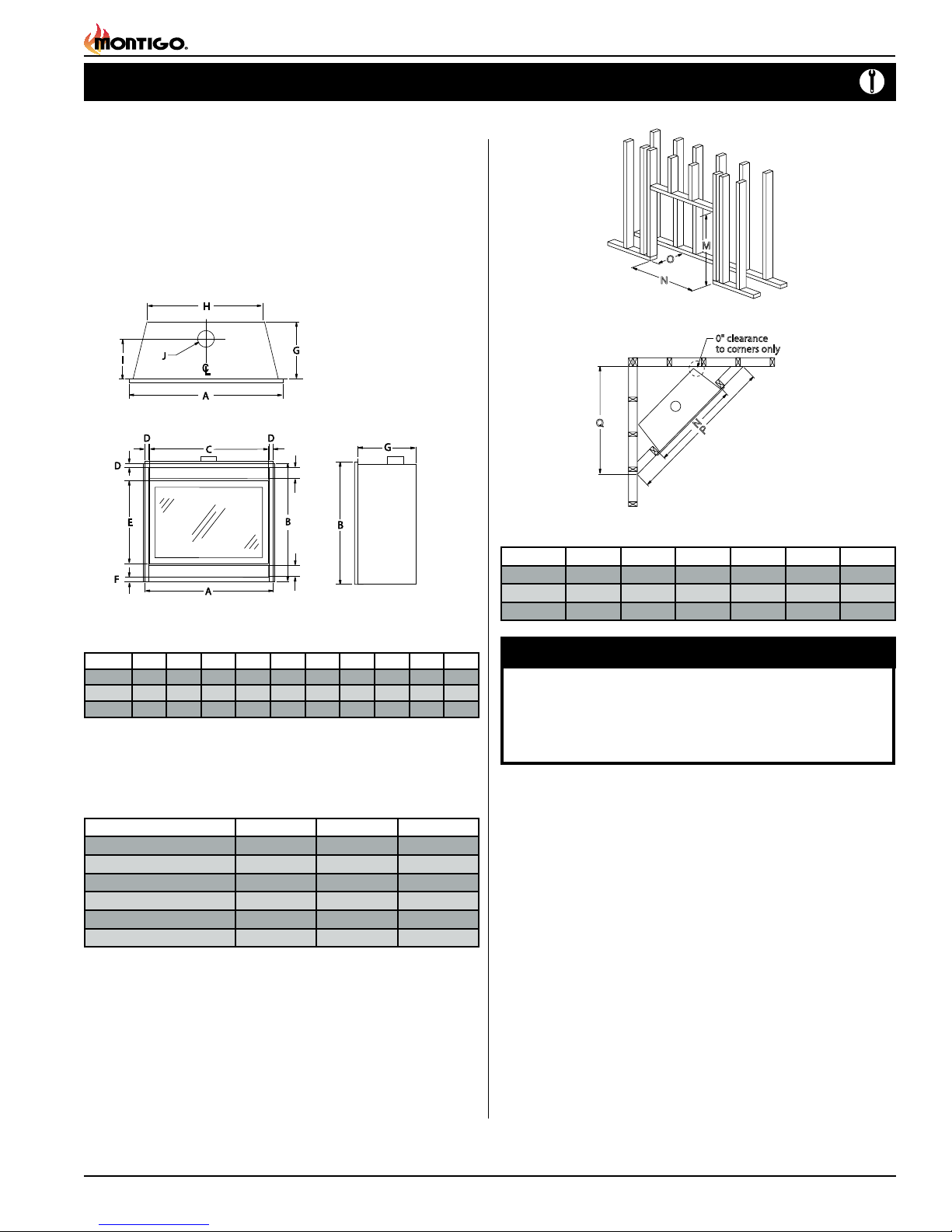
The replace dimensions are shown below:
Top View
Front View
Figure 1. Fireplace dimensions.
A B C D E F G H I J
7
1
1
1
H34BF
H38BF
H42BF
33
/
8 33
3
37
/
4 36
42 40
/
2 31
/
1
3
/
2 34
/
5
/
8 39 1
8 1
4 1
1
/
4 21
/
2 1 17
1
1
/
4 24
/
2 1 18
1
5
/
4 28
/
8 1 20 28 12
Clearances
These clearances apply to all dimensions except the framed opening,
where the clearance to combustibles is 0". The H-Series BF clearances
to combustible materials are:
Side View
3
7
/
8 21
/
8 10 4
1
/
2 25 11
1
/
2 4
1
/
2 4
Framing
* When sheetrock is
not used behind the
fireplace, framing
depth may be reduced
by 5/8"
Figure 2. Framing dimensions.
Figure 3. Minimum Corner framing dimensions.
M N O P Q R
H34BF
H38BF
H42BF
1
39
/
4 33
1
42
/
4 37
3
46
/
8 42 22
3
/
4 20 56
3
/
4 21
1
/
8 62 43
5
/
8 68 48
5
/
8 40 4
7
/
8 4
1
/
8 4
WARNING:
When this appliance is installed directly on carpeting, tile or
any combustible material other than wood ooring, it must be
installed on a metal or wood panel extending the full width and
depth of the appliance.
1
/
4
1
/
4
1
/
4
H34BF H38BF H42BF
Top - Ceiling
Back
Sides
Floor
Mantle**
Flue
* Clearance from the top of the replace to a combustible ceiling within the replace
enclosure.
8 Feet 8 Feet 8 Feet
2" 2" 2"
1" 1" 1"
0" 0" 0"
4" 4" 4"
1" 1" 1"
** Refer to page 11.
Unprotected combustible walls which are perpendicular to the replace
opening, must not project beyond the shaded area shown in Figure
25.
For protection against freezing temperatures, it is recommended that
outer walls of the chase be insulated with a vapor barrier. This will reduce
the possibility of a cold-air convection current on the replace.
Part No. XG0145
Page 3
H-Series BF Gas Fireplace
Gasline Access
0.875” dia.
2” height
to center
7”
to center
Burner Tray Gasket
Figure 4b. Gas line access.
Installation
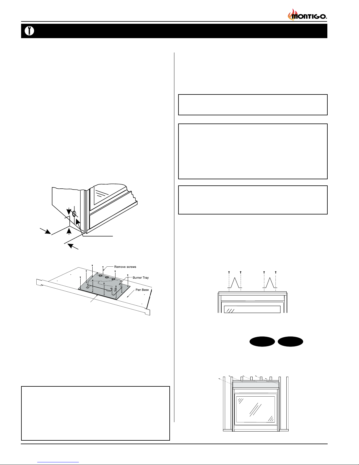
Installing The Gas Line
The gas line must be installed before nishing the H-Series BF Fireplace.
Natural Gas requires a minimum inlet gas supply pressure of 5.5" W.C.
& a manifold pressure of 3.5" W.C. Propane Gas requires a minimum
inlet gas supply pressure of 11" W.C. & a manifold pressure of 10" W.C.
Provision must also be made for a 1/8" N.P.T. plugged tapping and be
accessible for test gauge connection immediately upstream of the gas
supply controls to the appliance. The replace gas connection and
the main operating gas valve is located behind the removable trim at
the bottom of the unit and need only be attached to the gas line with
an approved tting, as required by the applicable installation codes.
To access the replace gas connection the main burner must be
removed as shown below in gure 4b.
• Only use gas shut-off valves approved for use by the state, province,
region, or governing body, in which the appliance is being installed, or
as required by the applicable installation codes.
• Flexible gas connectors must not exceed 3 feet in length, unless it is
allowable within applicable installation codes.
Vent Installation
The H-Series BF is certied for use with standard 4" B-Vent and requires
no B-Vent appliance connector. Simply attach the B-Vent to the replace
ue collar, and secure it using 1/4" sheet metal screws.
Refer to the current CAN/CGA B-149.1 and .2 or ANSI Z223.1-1998
Gas Installation Code for specic vent sizing.
Note: If more than 12 feet of B-Vent is used on the vent
runs, use ceiling supports.
Cautions:
■ Test your B-Vent installation after completion to ensure that
no combustible by products are spilling from the replaces
opening. This draft test should be performed after a three(3)
minute warm up period. The manufacturer will not be
responsible for any installations with inadequate draw.
Note: Due to the top vent clearances to combustible
materials there is no available shelf installation for
the H-Series BF replaces.
Figure 4a. Gas line access.
The appliance and its individual shut-off valve must be disconnected
from the gas supply piping system during any pressure testing of that
system at test pressures in excess of 1/2 psig (3.5 kPa).
The appliance must be isolated from the gas supply piping system by
closing its individual manual shut-off valve during any pressure testing
of the gas supply piping system at test pressures equal to or less than
1/2 psig (3.5 kPa).
Note: After gas line is connected, each appliance connection,
valve and valve train must be checked while under normal
operating pressure with either a liquid solution, or leak
detection device, to locate any source of leak. Tighten any
areas where bubbling appears or leak is detected until
Page 4
bubbling stops completely or leak is no longer detected.
DO NOT use a flame of any kind to test for leaks.
Installing The Standoffs
To avoid elevated mantel temperatures, all H-Series BF gas
replaces are required to have the supplied standoffs installed.
The replace is supplied with two standoffs. Bend and install these
standoffs on top of the replace ensuring that the height of the standoff
maintains a 6" clearance.
Figure 5. Installing the standoff's.
Installing the Nailing Flange
Extension
Once the replace is placed into the framed opening, the supplied
nailing extension must be placed along the top edge of the replace,
and nailed in place to the framing, as illustrated below.
Figure 6. Installing the Nailing Flange Extension.
H38BF
H42BF
Part No. XG0145
Installation
H-Series BF Gas Fireplace
Installing The Remote Switch
The H-Series BF's gas valve, located behind the lower trim, may be
connected to a wall switch. The valve generates its own power on a
millivolt circuit. Use only low voltage wire, and DO NOT connect
any external power to it.
Refer to Figure 30 for wiring requirements.
Note: The switch location must not exceed 30' from the replace.
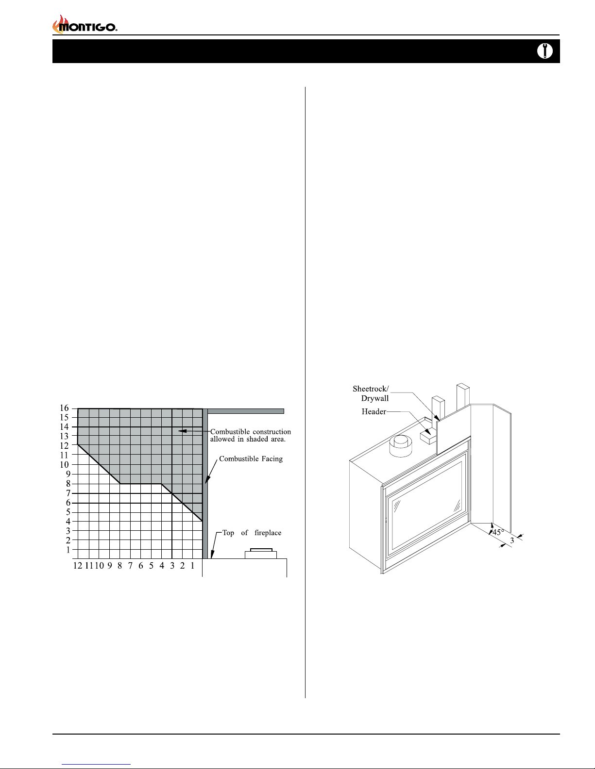
Finishing Around the Fireplace
Combustible mantels and mouldings may be safely installed over the
top and on the front of the replace provided that they do not project
beyond shaded area shown in Figure 7. Side wall clearances are 3".
Combustible surrounds may be installed with 3" clearance to the side
of the replace as shown in Figure 8.
Fireplace Facing
When selecting the nish material for your replace, it is important to
remember the following: THE PERFORATED VALVE COVER MUST
NOT BE OBSTRUCTED IN ANY WAY - to do so restricts the air
supply for the control compartments and heat exchanger it also
prevents access for servicing controls.
The face of the replace may be painted to match the room decor,
provided you use a heat-resistant paint. Decorative facing must not
extend past the replace opening at all, because it will interfere with
the access to retainers for removal of glass door.
Mantels & Surrounds
NOTE: National Canadian Gas Association mantel test requirements
are for re hazard prevention to combustible materials.
New technology, to meet consumer and government demands for the
wise use of energy, has prompted us to manufacture many models of
replaces which are hot, fuel and energy efcient.
Please be aware; temperatures over the mantel will rise above normal
room temperature and walls above replace may be hot to touch.
Warning:
When covering the upper metal portion of the replace with a noncombustible material Please Note: The decorative facing materials
may be subject to temperatures in excess of 250° F. This should be
considered when selecting facing materials.
We recommend careful consideration be given to the effects of elevated
mantel temperatures which may be in excess of product design, for
example: candles, plastic or pictures. This can cause melting, deformation,
discoloration or premature failure of T.V. and radio components.
Painting:
Special care is recommended by the Master Painters and Decorators
Association, when painting the replace surrounds, to select and apply
a quality Alkyd sealer prior to the applying of latex paints. This is to
prevent leaching of water from evaporation and causing a brownish
staining effect to paint over coats.
Figure 7. Combustible mantles and facings.
Part No. XG0145
Figure 8. Combustible surrounds.
Page 5

H-Series BF Gas Fireplace
Honeywell (Q3450)
Pilot Assembly
Pilot Electrical
Harness Connector
Honeywell Gas
Control (SV9501M)
Gas Control
Connector
Fuse
Limit
Switch
Wall
Switch
Fan Plug
Receptacle
Junction Box
Junction Box Cover
White
Black
Green
40 VA
Transformer
115VAC
24VAC
Grnd Screw
ADJ.
AUX Learn
Remote/Off
Continuous
Pilot
Off/On
S I
IPIPOWER
6VAC 200mA
AC ADAPTOR
Wall Switch (SWI)
Brown
Brown
Black
White
Green
White
Orange
Pilot
Main
Manual
Hi/Lo
Main Gas InputMain Gas Output
White (Sensor)
Orange (Igniter)
Control
Module
Emergency
Battery
Power
(4 x AA)
Pilot Assembly
Red
Black
Red
Black
O
p
tio
n
a
l
Wiring
Installation
Gas Control and Pilot Wiring
H-Series BF-I
Figure 9. Wiring for the H-Series BF-I with Honeywell gas control and pilot.
H-Series BF-A
Spill Switch
Gas Control and Pilot Wiring
Figure 10. Wiring for the H-Series BF-A with American Flame gas control
and pilot.
Page 6
Part No. XG0145
 Loading...