

Montigo E36DV-TV User Manual
ECONO-PLUS 36DV-TV
INSTALLING AND OPERATING
YOUR ECONO-PLUS 36DV
GAS-BURNING FIREPLACE
Please leave this manual with the owner
CHECK LOCAL CODES PRIOR TO INSTALLATION
FOR YOUR SAFETY FOR YOUR SAFETY:
IF YOU SMELL GAS:
1. OPEN WINDOWS. DO NOT STORE OR USE ANY FLAMMABLE
2. DON'T TOUCH ELECTRICAL SWITCHES VAPOURS OR LIQUIDS NEAR THIS OR ANY
3. EXTINGUISH ANY OPEN FLAME. OTHER GAS-BURNING APPLIANCE.
4. IMMEDIATELY CALL YOUR GAS SUPPLIER.
READ INSTRUCTIONS CAREFULL Y BEFORE INST ALLING
MODEL
ECONO-PLUS 36DV-TV
CANADIAN HEATING PRODUCTS INC.
13120 - 76th Avenue, Surrey, B.C. Canada; Phone: (604) 597-3115 Fax: (604) 597-3096
09/96
Page 1 of 14
E36DV-TV
INTRODUCTION
INSTALLING THE FIREPLACE
The Econo Plus 36DV-TV is rated at 16,000 BTUs. (4.16 Kilowatts)
for Natural & Propane gas.
The Econo Plus warranty will be voided by, and Econo Plus
disclaims any responsibility for, the following actions:
- Modification of the fireplace and/or components including
Direct-Vent assembly or glass doors.
- Use of any component part not manufactured or approved by
Econo Plus in combination with a Econo Plus fireplace system.
- Installation other than as instructed in this manual.
Consult your local Gas Inspection Branch about the particular
requirements concerning installation of factory-built gas fireplaces.
Installation & repairs should be done by a qualified contractor,
and installation must conform with the current CAN/CGA
B-149.1 and .2 Gas Installation Code and local
regulations.
CAUTIONS
* Due to its high operating temperatures, the appliance should be
located out of traffic & away from furniture and draperies.
* Children and adults should be alerted to the hazards of the high
surface temperature, which could cause burns or clothing ignition.
* Young children should be carefully supervised when they are in
the same room as the appliance.
* Clothing or other flammable materials should not be placed on
or near the appliance.
The Econo Plus 36DV-TV clearances to combustible materials are
0" back, 1" sides, 0" floor and 4" top. The Econo Plus 36DV-TV
must not be installed any closer than 8 inches to any unprotected
combustible wall perpendicular to the fireplace opening.
For protection against freezing temperatures, it is recommended
that outer walls of the chase be insulated with a vapour barrier. This
will reduce the possibility of a cold-air convection current on the
fireplace.
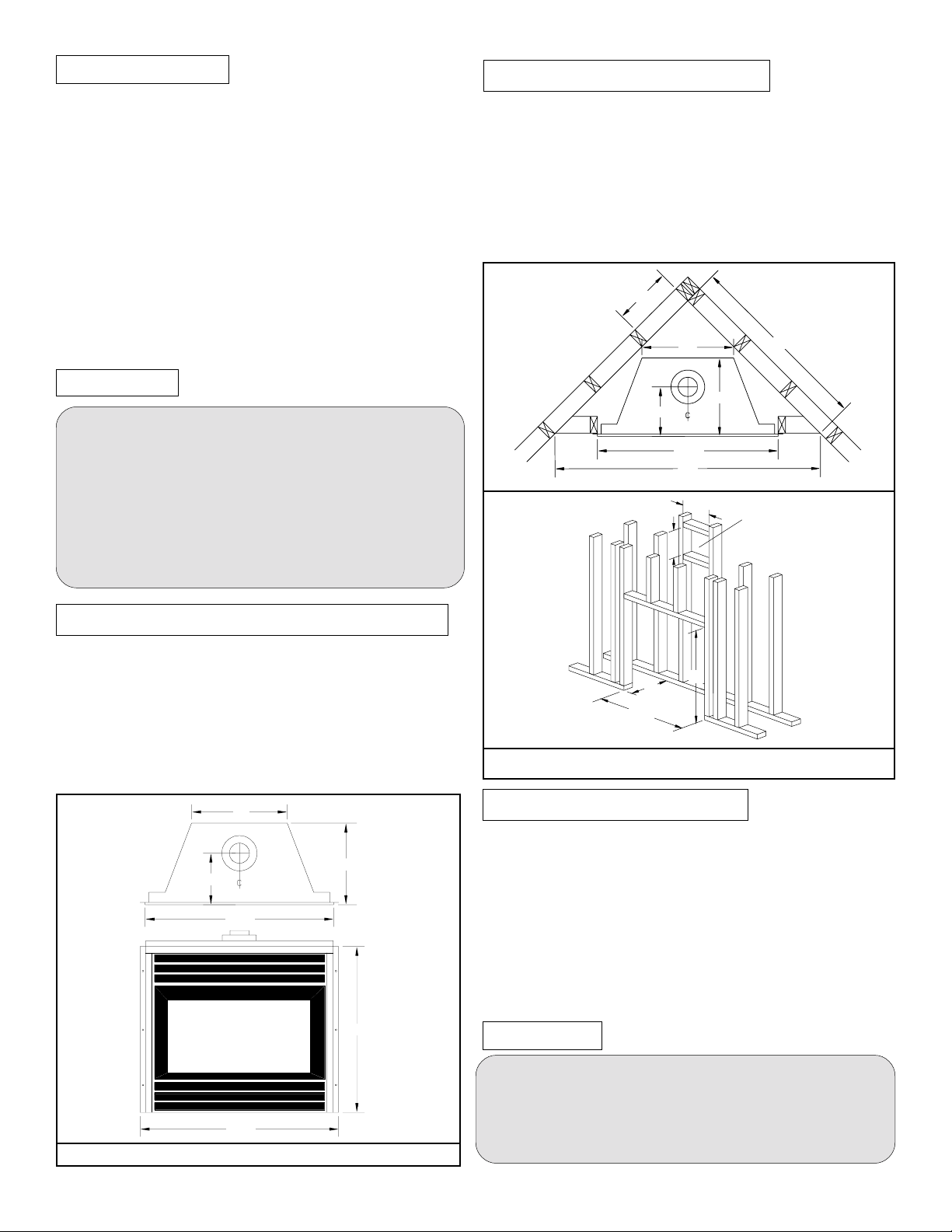
The framing dimensions are shown below:
12
19
16 1/4
10 1/4
37 1/2
55
12
12
39
Opening for termination.
42" min. from floor to
center of the opening.
SELECTING YOUR FIREPLACE LOCATION
The fireplace may be installed in any location that is free of air
condition ducts, electrical wiring and plumbing. Safety, as well as
efficiency of operation, must be considered when selecting the
fireplace location. Try to select a location that does not interfere
with room traffic, has adequate ventilation, and offers an accessible
pathway for Direct Vent & Combustion Air Kit installation.
The fireplace dimensions are shown below:
NOTE: SEE FIGURE 2 FOR FRAMING DIMENSIONS
19
16 1/4
10 1/4
37 1/2
33
39 1/2
FIGURE 1. FIREPLACE DIMENSIONS
09/96
36
17
37 1/2
FIGURE 2. FRAMING DIMENSIONS
INSTALLING THE GAS LINE
The gas line must be installed before finishing the Econo Plus
36DV-TV Fireplace. Natural Gas requires an inlet pressure of
7" W.C. & a manifold pressure of 3.5" W.C. Propane Gas
requires an inlet pressure of 11" W.C. & a manifold pressure of
10.5" W.C. It is also required that provisions be made for a
1/8" N.P.T. plugged tapping and be accessable for test gauge
connection immediately upstream of the gas supply controls to
the appliance. The fireplace gas connection and the main
operating gas valve is located behind the removable brass trim
at the bottom of the unit and need only be attached to the gas
line with an approved fitting, as required by the CAN/CGA
B-149.1 and .2 Gas Installation Code.
CAUTION
*After gas line is connected, it is a Can/CGA B149.1 & .2 code requirement
(Section 8.25.3 (e)) that "each appliance connection, valve, valve train, shall
be checked while under normal operating pressure with either a liquid solution,
or leak detection device, to locate any source of leak." Tighten any areas where
bubbling appears or leak is detected until bubbling stops completely or leak
is no longer detected. Do NOT use a flame of any kind to test for leaks.
Page 2 of 14
E36DV-TV
DIRECT VENT TERMINATION LOCATION
This section is used to determine where your direct
vent termination will be located.
VENT TERMINATIONS SHALL NOT BE RECESSED IN
WALLS OR SIDING.
CAUTION
1). Extremely important: In heavy snow areas take extra
care to prevent against blocking vent termination with
snow removal equipment.
2). Flue gases exiting vent terminals are very hot and must
not be restricted to assure fireplace combustion is not
affected.
3). Do not place, build any obstruction, plant any bushes
or for any reason attempt to conceal the vent
termination. To do so will affect the operation of
the fireplace and may be hazardous.
4). National Standards require that vent terminations be
protected with an additional screen on patio's, decks and
any areas accessible to public. For maximum safety we
recommend all terminals below 7' from grade level be
installed with a certified Econo Plus protective screen. (MTKG)
FOR DETAILED SKETCH OF ALLOWED
TERMINATION LOCATIONS SEE APPENDIX A
FOR VINYL SIDING APPLICATIONS ALL MTK
TERMINATIONS MUST BE INSTALLED WITH A
HEAT SHIELD (MTKG) TO PROTECT THE SIDING
FROM ANY HEAT DAMAGE. MTKO TERMINATIONS
DO NOT REQUIRE A HEAT SHIELD.
INSTALLATION OF DIRECT VENT
A complete Econo Plus 36DV-TV vent system may comprise of
six individual components: (see figure 5. page 4)
A - Termination MTK-5 (5" length)
MTK-9 (9" length)
B - Stucco Kits MSR (stucco frame)
MOSR (stucco can)
C - Solid section & elbow MIHR-6 (6 ft. length)
MIHR-10 (10 ft. length)
D - Flex sections MFL-1 (1' 6" section)
MFL-2 (2' 6" section)
MFL-3 (3' 6" section)
MFL-4 (4' 6" section)
E - Solid sections MEXT-1 (1' 6" section)
MEXT-2 (2' 6" section)
MEXT-3 (3' 6" section)
MEXT-4 (4' 6" section)
F - 90 degree elbow MEL90 (90 deg. elbow)
Example: For our shortest venting configuration use components A, B, and F. (see Figure 5).
Example: A 10' section and elbow (MIHR-10) used in
conjunction with 3 ft. flex section (MFL-3) will, when extended
in a five foot chase, allow for a maximum horizontal run of
twelve and one-half feet from the centre of the fireplace to
outside wall and a minimum of 7'6" when retracted in opposite
direction (see Figure 6 and 7).
"D" flex sections and "E" solid sections may be used in
conjunction with one another to obtain different possible
horizontal length installations. NOTE: Flex section must not
exceed maximum horizontal length of 3 feet. (see Figure 7.1)
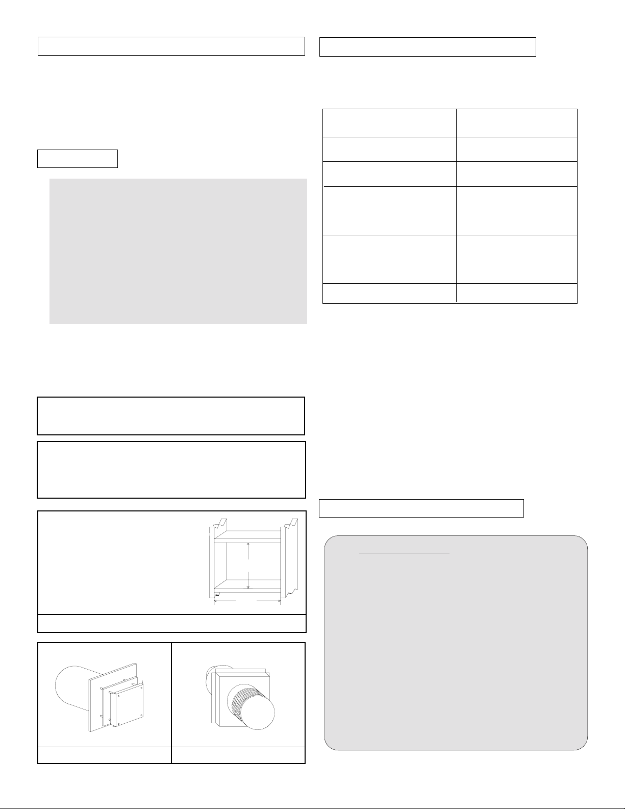
IMPORTANT:
When using MTK or MTKO with
MOSR: Framed opening must be 12"
X 12"
When using MTK or MTKO:
*
Framed opening must be 11" X 11"
FIGURE 4. VENT TERMINATION FRAMING.
MTK-5 or MTK-9 MTKO-5 or MTKO-9
09/96
*
*
12
12
CAUTIONS AND REQUIREMENTS
Note: DO NOT STRETCH flexible connector to gain
extra length. These connectors are Flexible only to
allow for directional changes, which must not exceed 90
degrees.
A minimum height of 43" to centre of horizontal flue is
required.
All vent pipes must maintain a minimum of 1"
clearance to combustible materials.
Note: It is imperative for satisfactory operation of the
Econo Plus 36DV-TV fireplace that no venting component be modified in any way. All components have been
manufactured to eliminate the need for modification
when properly selected and installed.
Page 3 of 14
E36DV-TV
 Loading...