

Montigo B34DV User Manual
www.montigo.com
Installation Operation & Maintenance Manual
Check local codes and read all instructions prior to installation.
B34DV Indoor
B-Series DV-2 Gas Fireplace
B34DV2 Black Trim Shown
Warning:
Improper installation, adjustment, alteration, service or maintenance can cause
injury or property damage. Refer to this manual. For assistance or additional
information consult a qualied installer, service agency or the gas supplier.
Safety Notice:
Glass doors on gas replaces are extremely hot while the replace is on and remain
hot even after the replace has been turned off. Safety screens are available and
can reduce the risks of severe burns. Please keep children away from the replace
at all times.
B38DV Indoor
Warning: If the infor-
mation in these instructions is not
followed exactly, a re or explosion
may result causing property damage, personal injury or death.
WHAT TO DO IF YOU SMELL GAS
• Do not try to light any appliance.
• Do not touch any electrical
switch; do not use any phone in
your building.
• Immediately call your gas
supplier from a neighbor's
phone. Follow the gas supplier's
instructions.
• If you cannot reach your gas
supplier, call the re department.
Installation and service must be
For Your Safety:
Do not store or use gasoline or other ammable vapors and liquids in the
vicinity of this or any other appliance.
®
C US
XG0160 Canadian Heating Products Inc. Langley, BC V4W 4A Montigo Del Ray Corp. Ferndale, WA 98248 141231
performed by a qualied installer,
service agency or the gas supplier.
• Installer: Leave this manual
with the appliance.
• Consumer: Retain this
manual for future reference.
B-Series DV-2 Gas Fireplace
Warning:
Read this manual before installing, operating or troubleshooting this appli-
ance. Please retain this owner's manual for future reference.
Congratulations!
Congratulations on selecting a Montigo gas replace, an elegant
and well designed gas replace built to your specications. The
Montigo gas replace you have selected is designed to provide
the utmost in safety, reliability, and engineering standards.
As the owner of this new replace, you'll want to read and carefully follow all the instructions contained in this Installation,
Operations and Maintenance manual. Pay special attention to all
cautions, warnings, and Important warnings.
This owner's manual should be retained for future reference. We
suggest that you keep it with all your other important documents
and product manuals.
The information contained in this owner's manual, unless noted
otherwise, applies to all models, and gas control systems.
Your new Montigo gas replace will give you years of durable,
reliable use. Welcome to the Montigo family of gas replace
products.
Safety Alert Key:
• DANGER!
Indicates a hazardous situation which, if not avoided will result in death or serious injury.
• WARNING! Indicates a hazardous situation which, if not avoided could result in death or serious injury.
• CAUTION! Indicates a hazardous situation which, if not avoided, could result in minor or moderate injury.
• NOTICE: Used to address practices not related to personal injury.
• Important: Used to address practices not related to personal injury.
Table Of Contents
Congratulations
Safety Alert Key
Introduction ............................................................................... 3
Installation
Installing and Framing the Fireplace .............................. 4
Installing the Gasline ...................................................... 5
The Remote Switch ........................................................ 6
Direct Vent Installation ................................................... 5
General Venting Requirements .........................5
Terminations ...................................................... 6
Top Vent Venting Runs ................................. 7 - 9
Rear Vent Venting Runs ........................... 10 - 11
Finishing around the replace
Facing .............................................................. 12
Mantels and Surrounds ................................... 12
Wiring ..................................................................13 - 14
Installing Optional Fans................................................ 13
Removing and Installing the Door ................................ 15
Installing the Horizontal Trim ........................................ 15
Positioning the Log set ................................................. 16
Operation .................................................................. 17 - 20
Maintenance .................................................................... 20 - 22
Spare Parts ................................................................. 22
Warranty ................................................................................. 23
Appendix
A. Termination Locations .............................................. 24
B State of Massachusetts / Amendment .................... 25
Page 2
Part No. XG0160 -141231
Introduction
B-Series DV-2 Gas Fireplace
Thank You for choosing a Montigo Gas Fireplace.
About this Fireplace:
The B-Series DV-2 is a dual burner replace with glowing embers.
The replace is available in three models, and in top or rear vent for
each model.
Standard Log Set
The B34DV-2 is rated for Natural Gas at 18,000 BTU/H (5.28
Kilowatts) Input or Propane at 18,000 BTU/H (5.28 Kilowatts) Input.
■ B34DT-2; Top Vent, Millivolt Pilot.
■ B34DR-2; Rear Vent, Millivolt Pilot.
■ B34DT-2-I; Top Vent, Intermittent Pilot (HSI).
■ B34DR-2-I; Top Vent, Intermittent Pilot (HSI).
■ B34DT-2-F; Top Vent, Electronic Ignition (IPI).
■ B34DR-2-F; Top Vent, Electronic Ignition (IPI).
Standard Log Set
The B38DV-2 is rated for Natural Gas at 21,000 BTU/H (6.16
Kilowatts) Input or Propane at 21,000 BTU/H (6.16 Kilowatts) Input.
■ B38DT-2; Top Vent, Millivolt Pilot.
■ B38DR-2; Rear Vent, Millivolt Pilot.
■ B38DT-2-I; Top Vent, Intermittent Pilot (HSI).
■ B38DR-2-I; Top Vent, Intermittent Pilot (HSI).
■ B38DT-2-F; Top Vent, Electronic Ignition (IPI).
■ B38DR-2-F; Top Vent, Electronic Ignition (IPI).
How to use this manual:
This manual covers installation, operation and maintenance. Lighting,
operation and care of this replace can be easily performed by the
homeowner. However, all installation and service work should be
performed by a qualied or licensed installer, plumber, or gastter who
is qualied or licensed by the state, province, region, or governing body
in which the appliance is being installed.
This manual covers all models and unless otherwise specied, the
designation B-Series DV-2 refers to all models. Sections which are
specic to a particular model are marked with a symbol, plus
the appropriate model number.
Warranty and Installation Information:
The Montigo warranty will be VOIDED by, and Montigo disclaims any
responsibility for, the following actions:
■ Modication of the replace and/or components including Direct-Vent
assembly or glass doors.
■ Use of any component part not manufactured or approved by Montigo in
combination with this Montigo replace system.
■ Installation other than as instructed in this manual.
Consult your local Gas Inspection Branch on installation requirements
for factory-built gas replaces. Installation & repairs should be done by
a qualied contractor.
Installations in Canada must conform to the current CAN/CGA B-149.1
and .2 Gas Installation Code and local regulations. If the optional aircirculating fan kit is installed, it must be electrically grounded in accordance
with CSA C22.1 Canadian Electrical Code Part 1 and/or Local Codes.
Installations in the USA must conform to local codes, or in the absence
of local codes to the National Fuel Gas Code, ANSI Z223.1-1988. If the
optional air-circulating fan is installed, it must be grounded in accordance
with local codes or, in the absence of local codes, with the National
Electrical Code, ANSI/NFPA 70-1987. See Appendix B for installation
within the State of Massachusetts.
CAUTION!
Due to its high operating temperatures, the appliance should
be located out of trafc & away from furniture and draperies.
Children and adults should be alerted to the hazards
of the high surface temperature, which could cause
burns or clothing ignition.
Young children should be carefully supervised when
they are in the same room as the appliance.
Clothing or other ammable materials should not be
placed on or near the appliance.
Part No. XG0160 - 141231
WARNING
HOT GLASS WILL
CAUSE BURNS.
DO NOT TOUCH GLASS
UNTIL COOLED.
NEVER ALLOW CHILDREN
TO TOUCH GLASS.
Page 3
B-Series DV-2 Gas Fireplace
M
N
O
Head
Installation
Installing and Framing the Fireplace
The B-Series-DV-2 replaces may be installed in any location that maintains proper clearances to air conditioning ducts, electrical wiring and
plumbing. Safety, as well as efciency of operation, must be considered
when selecting the replace location. Try to select a location that does
not interfere with room trafc, has adequate ventilation, and offers an
accessible pathway for Direct Vent installation. Refer to page 5 - Vent
Installation for more information.
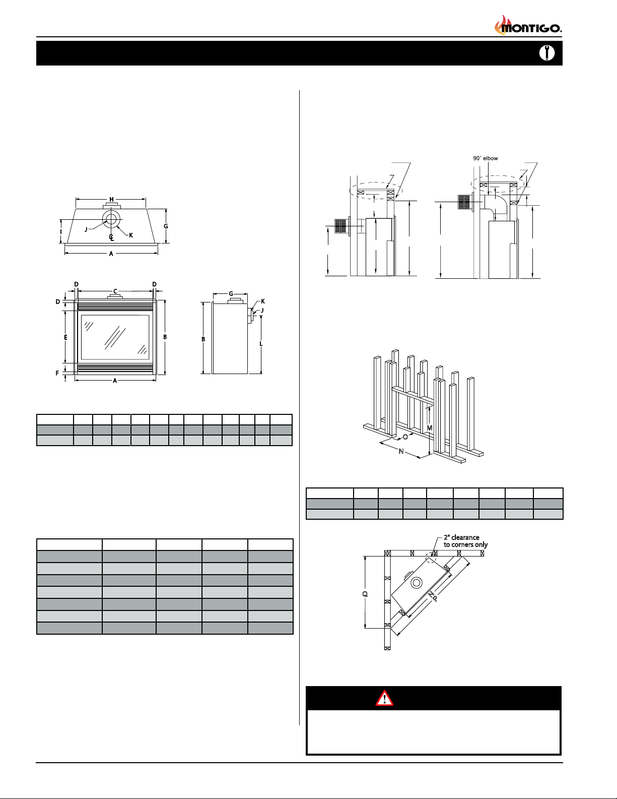
The replace dimensions are shown below:
Top View
When installing a shelf over the top of the replace, the following guidelines
must be adhered to: For Rear Vent applications the minimum clearance
from the top of the replace to a shelf is 8". For Top Vent applications, the
minimum clearance is 15". (
Minimum clearance to combustible construction
around the vent pipe is 1" on all sides, except on horizontal venting where the
top of the pipe must have a clearance of at least 2".
er
Shelf
8”
T
L
Rear Vent
S
(On Applicable Models)
M
)
MEL Short
15”
Top Vent
Header
Shelf
2” Min
M
Figure 2. Framing for shelves over the replace.
Framing
Front View Side View
A B C D E F G H I J K L
3
1
1
B34-DV-2 33
B38-DV-2 37
/
3
/
4 31
4 34
/
1
/
2 31
2 34
1
/
4 1
/
4 18 1 13
3
1
/
4 1
/
4 21 1 15
3
3
/
4 21
/
4 8 4 7 25
7
1
/
8 24
/
8 9 4 7 28
1
/
4
3
/
8
Figure 1. Fireplace dimensions.
Clearances
These clearances apply to all dimensions except the framed opening,
where the clearance to combustibles is 0". The B-Series DV-2 clearances
to combustible materials are:
B34-DV-2-TV B34-DV-2 RV B38-DV-2-TV B38-DV-2-RV
Top - Rear Vent * N/A 8" N/A 9 1/4"
Top - Top Vent 15" N/A 15" N/A
Back 0" 1" 1" 1"
Sides 1" 1" 0" 0"
Floor 0" 0" 0" 0"
Mantle** 8" 8" 6" 6"
Flue 1 1/2" 1 1/2" 1" 1"
* Clearance from the top of the replace to a combustible ceiling
within the replace enclosure.
** Refer to page 12, (Mantels and Surrounds).
Unprotected combustible walls which are perpendicular to the replace
opening, must not project beyond the area shown in Figure 23.
For protection against freezing temperatures, it is recommended that
outer walls of the chase be insulated with a vapor barrier. This will reduce
the possibility of a cold-air convection current on the replace.
(When sheetrock is
not used behind the
replace, framing
M
O
N
depth "O" may be
reduced by 5/8")
Figure 3. Framing dimensions.
L M N O P Q S T
1
B34-DV-2 25
B38-DV-2 28
3
Q
/
4 36
/
8 39
3
/
4 33 15
3
/
4 37 17
1
/
2 50 35
5
/
8 56 39
2" clearance
to corners only
N
P
3
/
8 30
5
/
8 33
3
/
8 39
3
/
8 42
Figure 4. Minimum Corner framing dimensions, using a 45° elbow.
WARNING!
When this appliance is installed directly on any combustible material other than wood ooring, it must be installed on a metal or
wood panel extending the full width and depth of the appliance.
7
/
8
7
/
8
Page 4
Part No. XG0160 -141231
Installation
B-Series DV-2 Gas Fireplace
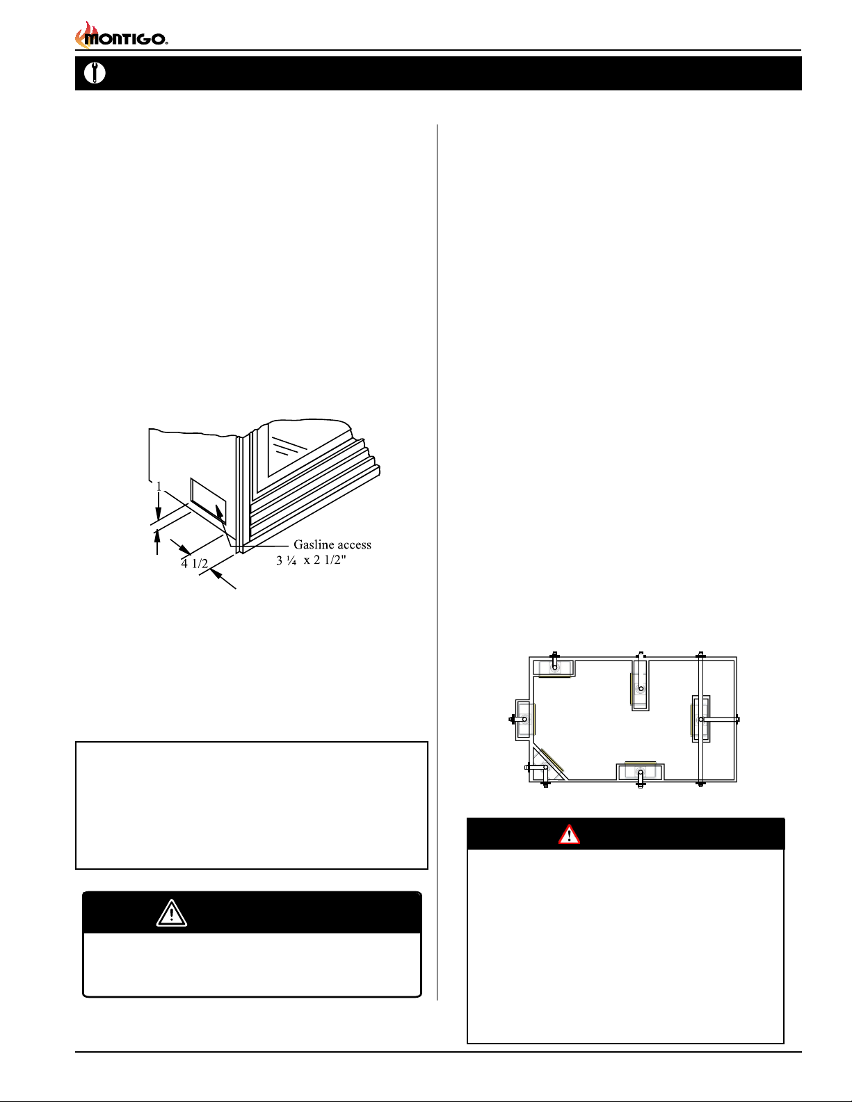
Installing The Gas Line
The gas line must be installed before nishing the B-Series DV-2
Fireplace. Natural Gas requires a minimum inlet gas supply pressure
of 5.5" W.C. & a manifold pressure of 3.5" W.C. Propane Gas requires a
minimum inlet gas supply pressure of 11" W.C. & a manifold pressure of
10" W.C. Provision must also be made for a 1/8" N.P.T. plugged tapping
and be accessible for test gauge connection immediately upstream of
the gas supply controls to the appliance. The replace gas connection
and the main operating gas valve is located behind the removable trim
at the bottom of the unit and need only be attached to the gas line with
an approved tting, as required by the applicable installation codes.
• Only use gas shut-off valves approved for use by the state, province,
region, or governing body, in which the appliance is being installed, or
as required by the applicable installation codes.
• Flexible gas connectors must not exceed 3 feet in length, unless it is
allowable within applicable installation codes.
Vent Installation
This section covers the installation of direct venting and terminations.
Installation Requirements
■
B-Series DV-2 replaces are certied for use with Montigo Standard Series
(4" / 7") venting components.
■ Minimum clearance to combustible construction around the vent pipe
is 1" on all sides, except on horizontal venting where the top of the pipe
must have a clearance of at least 2".
■ Use only certied Montigo vent components. (Use of other parts will void
the Montigo warranty, and may impede the operation of the replace.)
■ Connect all vent sections using a minimum of three sheet metal screws on
the outer pipe ue.
■ Vent terminations must not be recessed in walls or siding
Ensure all runs are supported with a minimum of 3 supports per 10’ of venting.
■
■ Flex vent sections may be stretched up to 50% of their total length (eg. a
24" section may be stretched to 36")
■ Maximum horizontal run for a ex section with no vertical rise is 3 feet.
■ Flex vent sections over 3 feet must fall within the limits set by the venting
graph and must have a minimum vertical rise of 3 inches per foot of ex.
■ Solid vent sections may be cut less than half way from the female end
■ Venting components can be used in any combination of solid/rigid pipe or ex
pipe and in any orientation (Male connectors can face in any direction)
Figure 5. Gas line access.
The appliance and its individual shut-off valve must be disconnected
from the gas supply piping system during any pressure testing of that
system at test pressures in excess of 1/2 psig (3.5 kPa).
The appliance must be isolated from the gas supply piping system by
closing its individual manual shut-off valve during any pressure testing
of the gas supply piping system at test pressures equal to or less than
1/2 psig (3.5 kPa).
Note: After gas line is connected, each appliance connection,
valve and valve train must be checked while under normal
operating pressure with either a liquid solution, or leak
detection device, to locate any source of leak. Tighten
any areas where bubbling appears or leak is detected until
bubbling stops completely or leak is no longer detected.
DO NOT use a ame of any kind to test for leaks.
WARNING
When installing the replace - gas lines, ttings,
accessories or any other objects cannot impede the
proper movement of the door buckles.
Vent Terminations
Selecting A Termination Location
Choosing your vent termination location will help to determine whether
you need to use a top vent or rear vent replace. Figure 6, below, shows
typical replace locations and the venting options they provide.
For a more detailed diagram of allowed termination locations, see
Appendix A.
Figure 6. Fireplace locations and vent terminations.
Cautions:
Vent terminations can be very hot. If the termination is less than 7 feet
above a public walkway, it should be tted with a certied Montigo
Heat Guard. (Part no. PTKOG).
Do not obstruct, or attempt to conceal the vent termination.
These actions will affect the operation of the replace, and may
be hazardous.
In heavy snow areas, take extra care to prevent snow buildup
from obstructing the vent termination.
Use Montigo Vinyl Heat Shield (Part no. VSS) when using on
applications with vinyl siding to guard against possible damage.
Part No. XG0160 - 141231
Page 5
B-Series DV-2 Gas Fireplace
MIN
Installation
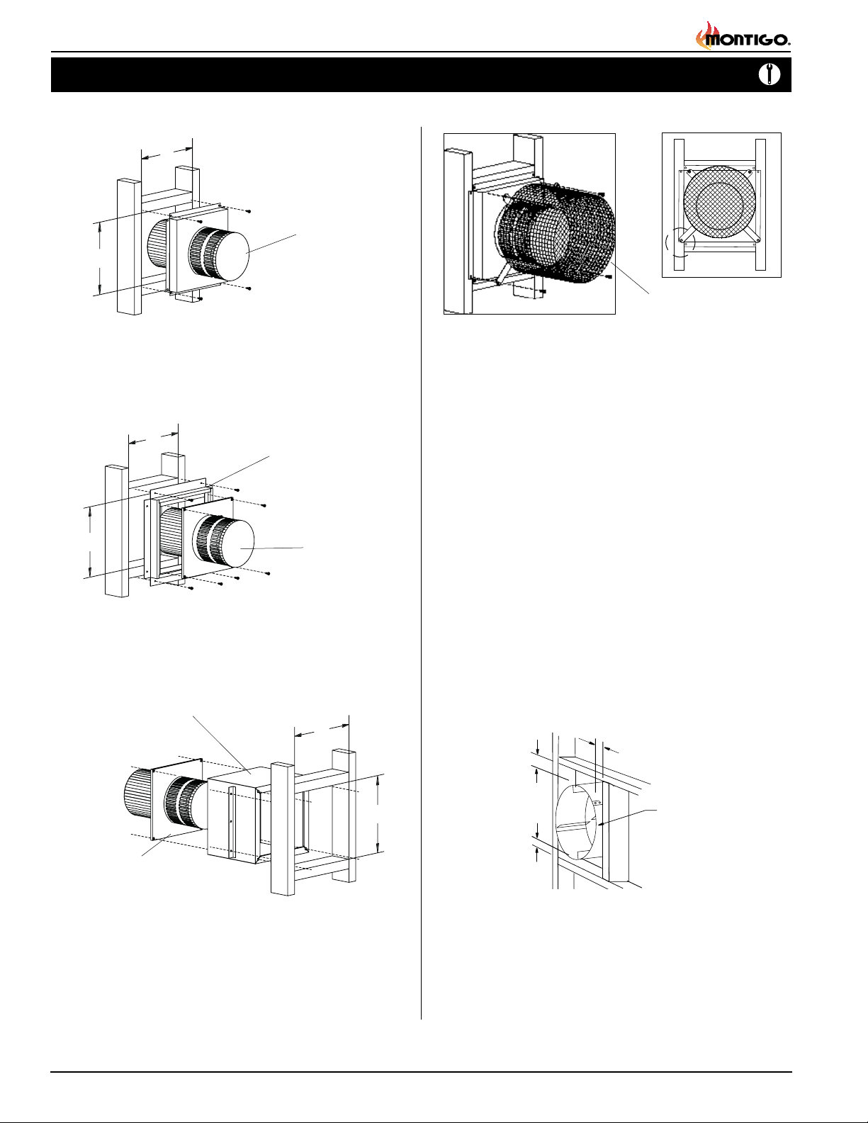
Installing Terminations with Built-In Frames
11
MTO-4F (4"/7")
11
PTO-3F (5"/8")
1. Frame the termination opening to 11" x 11".
2. Fasten the termination to the studs using a minimum of 4
screws.
Installing Terminations with MSR Frames
12
MSR
12
MTO-4F (4"/7")
PTO-3F (5"/8")
1. Frame the termination opening to 12" x 12".
2. Fasten the termination to the studs using a minimum of 4 screws.
Installing Terminations with MOSR Frames
MOSR
12
Installing Heat Guards over Terminations
MTKOG (4"/7")
PTKOG (5"/8")
1. Ensure that the two long mounting brackets are facing the bottom
of the termination. (See inset). This will provide more heat protection
at the top of the termination, where temperatures are highest.
2. Attach to the faceplate of the termination using four sheet metal
screws.
Installing The Remote On/Off Wall Switch
The B-Series DV-2's gas valve, located behind the lower trim, may be
connected to a wall switch. The valve will either generate its own power
on a millivolt circuit or draw its power from an AC connection inside
the replace, depending on the model of your unit. Use only low voltage
wire, and DO NOT connect any external power to the remote switch.
Refer to Figure 24, 26, or 30 for wiring requirements.
Note: The switch location must not exceed 30' from the replace.
Heat Shields
Due to high ue temperatures, heat shields are required on all B Series
DV-2 installations (except those with vertical terminations) at the point
where the venting connects to the termination. With the heat shield, vent
clearances can be maintained at 1”.
1
1 MIN. Both
sides Typical
MTO-4F (4"/7")
PTO-3F (5"/8")
1. Frame the termination opening to 12" x 12".
2. Fasten the MOSR frame to the interior side of the studs using a
minimum of 4 screws.
3. Insert the termination into the MOSR frame as shown here, and
attach by screwing through the four pilot holes in the termination.
Page 6
12
RHS8 Heat
Shield
1 MIN
Figure 7. RHS8 Installation. (Install by sliding over vent pipe where it
passes through the combustible construction.
Part No. XG0160 -141231
Installation
B-Series DV-2 Gas Fireplace
Top Vent Venting Runs
For the B-Series DV-2 Top Vent, there are two types of installations:
A) Through-The-Wall Installations and B) Vertical (Through-The-Roof)
Installations.
Through-The-Wall Installations
Before you install any venting, you must determine whether the venting
run will be acceptable. Unacceptable venting can affect the replace's
combustion.
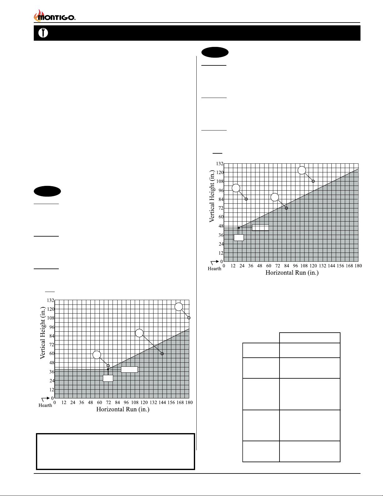
The Venting Graph
Measure the vertical height from the replace hearth to the centre of the
termination and the horizontal run from the from the replace ue collar
to the wall ange of the termination. Plot on the Venting Graph (Fig. 8)
or (Fig.8a) with an 'X'.
If the 'X' falls on or above the top boundary of the shaded area, the
installation is acceptable.
B34DV-2
Example A: (Acceptable Installation)
If the vertical dimension from the hearth is 108" and the horizontal run to
the wall ange of the vent termination is 180", this would be an acceptable installation.
Example B: (Acceptable Installation)
If the vertical dimension from the hearth is 44" and the horizontal run to
the wall ange of the vent termination is 72", this would be an acceptable
installation.
Example C: (Unacceptable Installation)
If the vertical dimension from the oor of the replace is 60" and the horizontal run to the wall ange of the vent termination is 144", this would
NOT be an acceptable installation.
B34DV-2
B38DV-2
Example A: (Acceptable Installation)
If the vertical dimension from the hearth is 84" and the horizontal run to
the wall ange of the vent termination is 36", this would be an acceptable
installation.
Example B: (Acceptable Installation)
If the vertical dimension from the hearth is 108" and the horizontal run to
the wall ange of the vent termination is 120", this would be an acceptable
installation.
Example C: (Unacceptable Installation)
If the vertical dimension from the oor of the replace is 72" and the
horizontal run to the wall ange of the vent termination is 84", this would
NOT be an acceptable installation.
A
18
”
B38DV-2
B
C
42 7/8”
Figure 8a. B38-DV-2 Top Vent Venting Graph
C
B
39 7/8”
72
”
Figure 8. B34-DV-2 Top Vent Venting Graph
NOTES: All dimension lengths for vertical or horizontal runs are
measured from centre of the vent pipe. Venting runs must
fall within the limits set by the venting graph (Fig 8 or 8a).
Part No. XG0160 - 141231
A
Available Top Vent Components
The following venting components are available for the B-Series DV-2
Top Vent:
4" / 7" Venting
A - Termination TO-4 (3" Length)
B - Stucco Kits MSR (Stucco Frame)
C - Flex Sections MFL-1 (12" f/f Section)
D - Rigid
Sections
E - Elbows MEL-90MM (m/m 90° Elbow)
M
MTO-4F (3" Length)
MOSR (Stucco Can)
BSR ( Brick Can)
MFL-2 (24" f/f Section)
MFL-3 (36" f/f Section)
MFL-4 (48" f/f Section)
MFL-6 (72" f/f Section)
MEXT-1 (12" mf Section)
MEXT-2 (24" m/f Section)
MEXT-3 (36" m/f Section)
MEXT-4 (48" m/f Section)
MEXT-6 (72" m/f Section)
MEL-90FF (f/f 90° Elbow)
MEL-90FM (f/m 90° Elbow)
Page 7
B-Series DV-2 Gas Fireplace
Installation
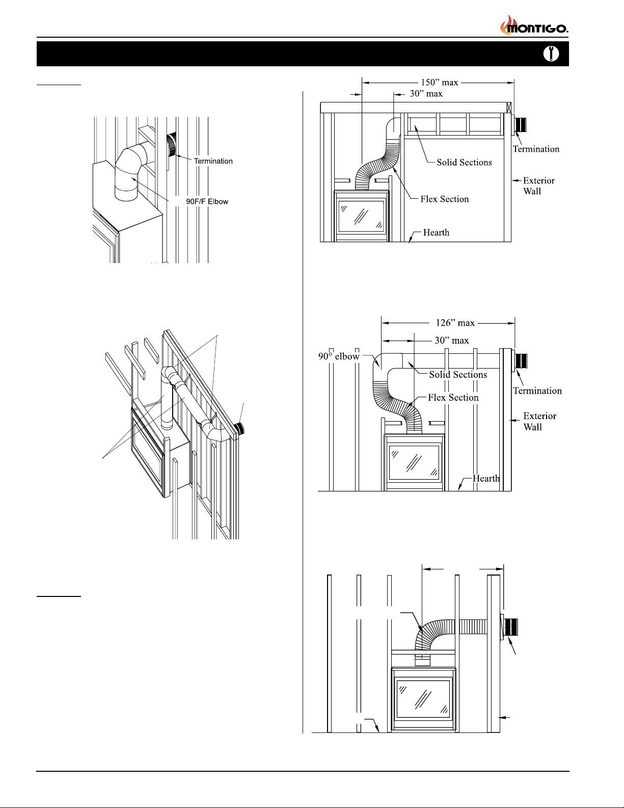
Example 1:
For our shortest venting conguration use components A and E (see
table on page 7).
PEL
Figure 9. Typical Top Vent installation. If the 90° elbow is installed
directly on the replace, for height to the center of the
termination see chart on page 4.
Horizontal Venting
90° Elbow
Termination
MEXT Section
Figure 10. Typical Top Vent installation. The solid sections can be used
in various combinations to obtain the desired vent run. The
vent run must fall within the limits set by the venting graph.
Figure 11. Extended Installation using a combination of solid and ex
venting. Use the vent graph to determine your allowable
run, then select appropriate components.
Figure 12. Retracted Installation using a combination of solid and ex
venting. Use the vent graph to determine your allowable
run, then select appropriate components.
36” max.
Example 2:
Rigid sections and an elbow used in conjunction with 3 ft. ex section
(MFL-3) will, when extended in a ve foot chase, allow for a maximum
horizontal run of twelve and one-half feet from the centre of the replace
to outside wall and a minimum of 7'6" when retracted in opposite direction
(see Figure 11).
"C" ex sections and "D" rigid sections (See table on page 7) may be
used in conjunction with one another to obtain different possible horizontal
length installations, Figure 12.
NOTE: Flex section with no vertical rise must not exceed maximum
horizontal length of 3 feet (see Figure 13). Flex runs over 3 feet must
fall within the limits set by the venting graph, and must have a minimum
vertical rise of 3" per foot of ex.
Page 8
Flex Section
Termination
Hearth
Exterior
Wall
Figure 13. Horizontal ex installation with no vertical rise.
Part No. XG0160 -141231
 Loading...