

Montgomery Ward ZDW-57061A, ZDW-57062A Owner's Manual
·--
-~-::
' '
.
...
v-·
.-~~
·
""~·-\:"~
~
r\
·.
~~.
*:I
.
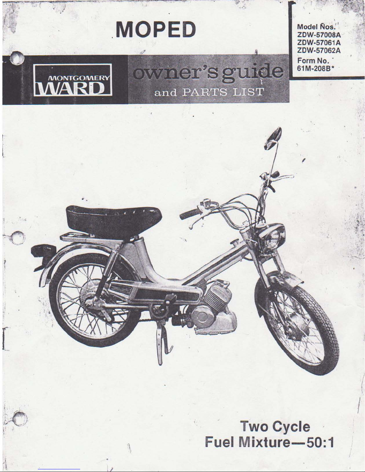
MOPED
Model
ZDW-57008A '!
ZDW-57061A !
ZDW-57062A
Form
61M-208B*
~os
:'
' · .~1
No.·
[
.,
·
...
~(
..
. ,
-..
~·AJ
l
I
(
\
, .
..-.
. . . \
·
·
~
/;
https://manualmachine.com/
Fu
Two Cycle
el
M
ixture-50:1
I
;:::;z
--~---~~~~
e.
--
~-~~~-----~~
I •
•
..
/
Local licensing, age and
TRAINING
1. Read
thor
proper use
2. Never
without
Children should be of
understanding and capacity.
PREPARATION
1.
Check fuel before starting engine. Fuel
mixture
of
Indoors, when engine is running,
engine is
gasoline before starting the engine.
2.
Never start
proper starting position.
the
oughly
allow
proper and close
50:1
regular gasoline). Do
SAFE OPER ATION PRACTICES
traffic
Owner's Manual carefully. Be
familiar
of
the equipment.
children
(2112
still
this
oz.
hot.
MOP
with
the
to
operate a MOPED
adult
sufficient
two
cycle
not ·fill
Wipe
ED
See
off
without
page
IMPORTANT
regulatl.
controls
oil
gasoline tank
ons
may vary
and
sup
ervision.
age,
to 1 gallon
or
while
the
any spilled
being in
9.
MAINTE
1. Keep
2.
from
state
to
state. Check existing local laws.
3.
It
is the absolute understanding that
is
not
a field bike.
comply
requ irements
responsibi
4. The operator should never place
feet
parts.
5. This
ONLY.
6. T
his
manner, such as
hill
7. This
such as pavement.
8. Never operate
surface.
sure the
Never store the unit inside
gasoline in the tank where the fumes may
reach
engine
enclosure.
with
the
lity of. the purchaser.
or
any part
MOPED is designed for ONE AIDER
Carrier
MOPED should not be used in a reckless
climb
MOPED
NANCE AN D STORAGE
all
unit
an
to
is
ing.
is
this
nuts,
is
in
open flame
cool
Any
licensing needed
existing local
In any given area is the sole
of
his body near any moving
not
for
passengers.
jumping
designed
MOPED on wet
bolts
, and screws
a safe operating
or
before
or
obstacles, racing
for
hard surfaces,
of a building
spark.
storing
this
state vehicle
his
hands,
or
slippery t
tight
condition.
Allow
in any
to
with
the
unit
to
or
i:
be
OPERATION
;
I
I
1i.:
I
..
~
,
•.
\
,.'!,
\,
\'
1. It
is
recommended
helmet and eye protection.
2.
Manufacturer recommends running
lights
on.
the
operator use a safety
with
3.
Prior
checked and maintained. Front: 25
Rear: 32 P.S.I. Maximum
rear.
4. The tightness
checked after every few hours
See Spoke Adjustment on page 15 .
2
to
each use, the tire pressure should be
P.S.I.,
36
P.S.I.
of
the spokes should
front
of
operation.
and
be
-
CONTENTS
Safe Operation Practices
Index and Know Your MOPED
Consumer Information
Tire Reserve Load
Identification
Assembly
Prepare
Operating
Maintenance
Adjustments
Wiring Diagram
Instructions
for
Operation
....
............
..............
.........
..........
........................
............
....................
......................
......................
.......................
...
..
.........
.....
..
....
. .
.
.........
.
...............
.................
................
KNOW
.
........
.
..
....
YOUR MOPED
...
...
2
3
4
5
6
6
8
9
10
13
17
Exploded
Parts List
Exploded
Parts
Exploded View for Torque Converter . .
Exploded View and Parts
Exploded View and Parts
Exploded View and Parts
Exploded View and Parts List for Engine
Parts Ordering Procedure
VIew for Fork and Handle Bar
for
Fork and Handle Bar
View
for
Main Frame
List
for
Main Frame
................
List
for Front Wheel
List
for
List
for
...........
............
.......
Rear Wheel
Controls
....
...
18
19
..
......
........
.... 27-
Back Cover
20
21,
22
23
24
...
25
..... 26
31
FIGURE
,._
1 .
2.
3.
4.
5.
6.
7.
8.
9.
10
.
11.
/ 12.
13.
14.
h
1.
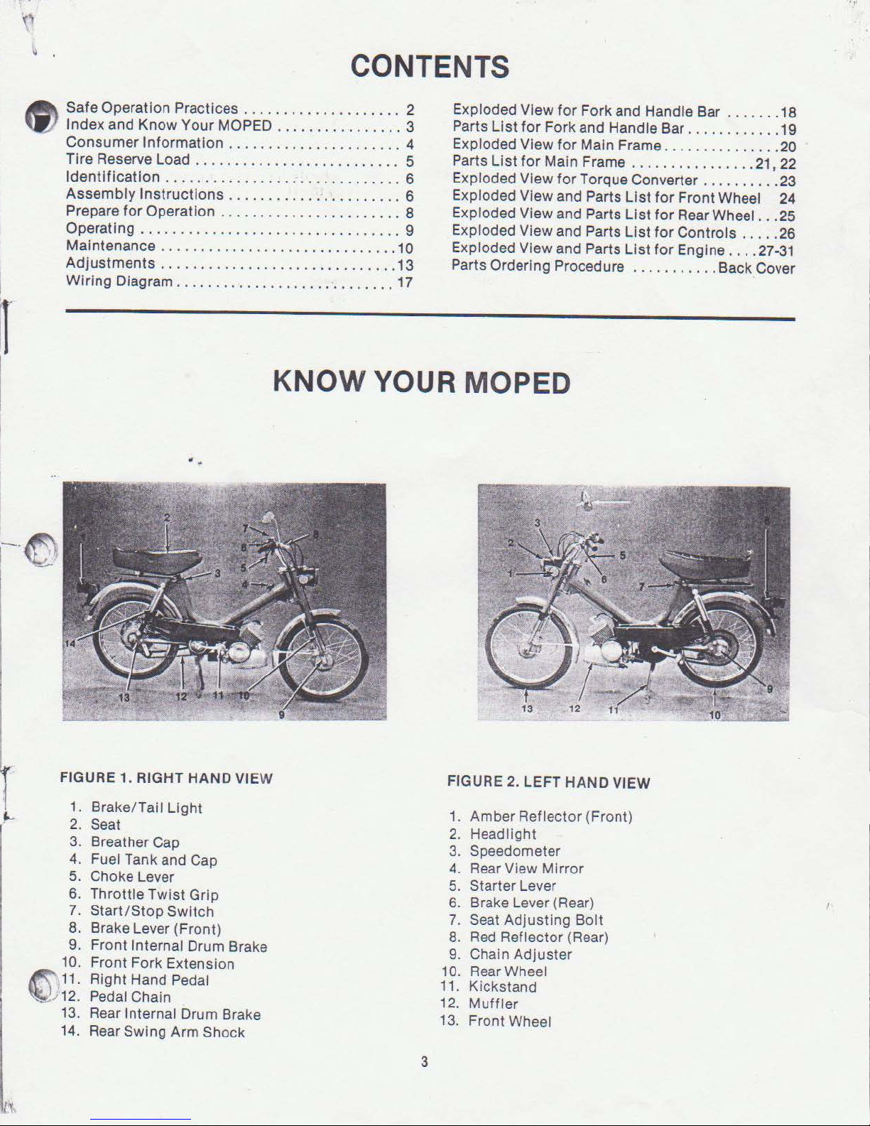
RIGHT HAND VIEW
Brake/Tal
Seat
Breather Cap
Fuel Tank and
Choke Lever
Throttle Twist Grip
Start/Stop
Brake Lever (Front)
Front Internal Drum Brake
Front Fork Extension
Right Hand Pedal
Pedal
Rear
Rear Swing Arm Shock
I Light
Cap
Switch
Chain
Internal Drum Brake
FIGURE 2. LEFT HAND VIEW
1.
Amber Reflector (Front)
2. Headlight
Speedometer
3.
4. Rear View Mirror
Starter Lever
5.
6. Brake Lever (Rear)
7. Seat Adjusting
8.
Red
Reflector (Rear)
Bolt
9. Chain Adjuster
10. Rear Wheel
11.
Kickstand
12.
Muff
ler
13. Front Wheel
3
1979 MOPED
CONSUMER
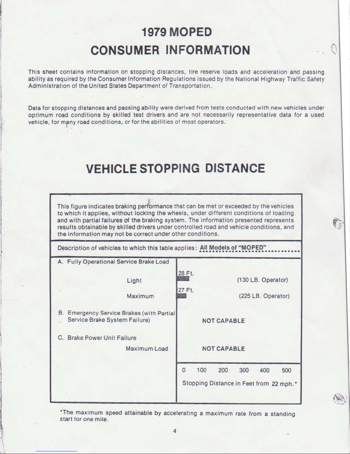
This sheet contains Information on stopping distances, tire reserve loads and acceleration and passing
ability
Administration
as required by the Consumer Information Regulations issued by the National Highway Traffic Safety
of
the United States Department
INFORM
of
Transportation.
·ATION
0
0
•
Data for stopping distances and passing
optimum
vehicle, for
road
mrny
conditions
road conditions,
by skilled test drivers and are not necessarily representative data for a used
or
for the
VEHICLE STOPPING DISTANCE
This figure Indicates braking performance that can be met
to which
and with
resul
the
De
scription
A. F
it
applies, with o
partial failures
ts
obtainable by skilled drivers under controlled road and vehicle conditions, and
Information may n
of
vehicles
ully
Operational Service Brake Load
ut
locking the wheels, under different conditions
of
the braking system. The Information presented represents
ot
be correct under other conditions.
to
which
Light
Maximum
ability
were derived from tests conducted
abilities
thi
s table applies: All Models
of
most operators.
·· ·· ······ ·············· M
28Ft.
,.Ft.
with
new vehicles under
or
exceeded by the vehicles
of
loading
of "MOPED
"
(130 LB. Operator)
(225 LB. Operator)
····
··
B. Emergency
Service Brake System Failure)
C.
Brake Power Unit Failure
*The
maximum speed
for
start
Service Brakes (with Partial
one mile.
NOT CAPABLE
Maximum Load
0 100
Stopping Distance in Feet from 22 mph. •
att
ainable by accelerating a maximum rate from a standing
4
NOT CAPABLE
200
300
400
500
This
table
lists
which
~
percentage
it
applies,
V I each vehicle
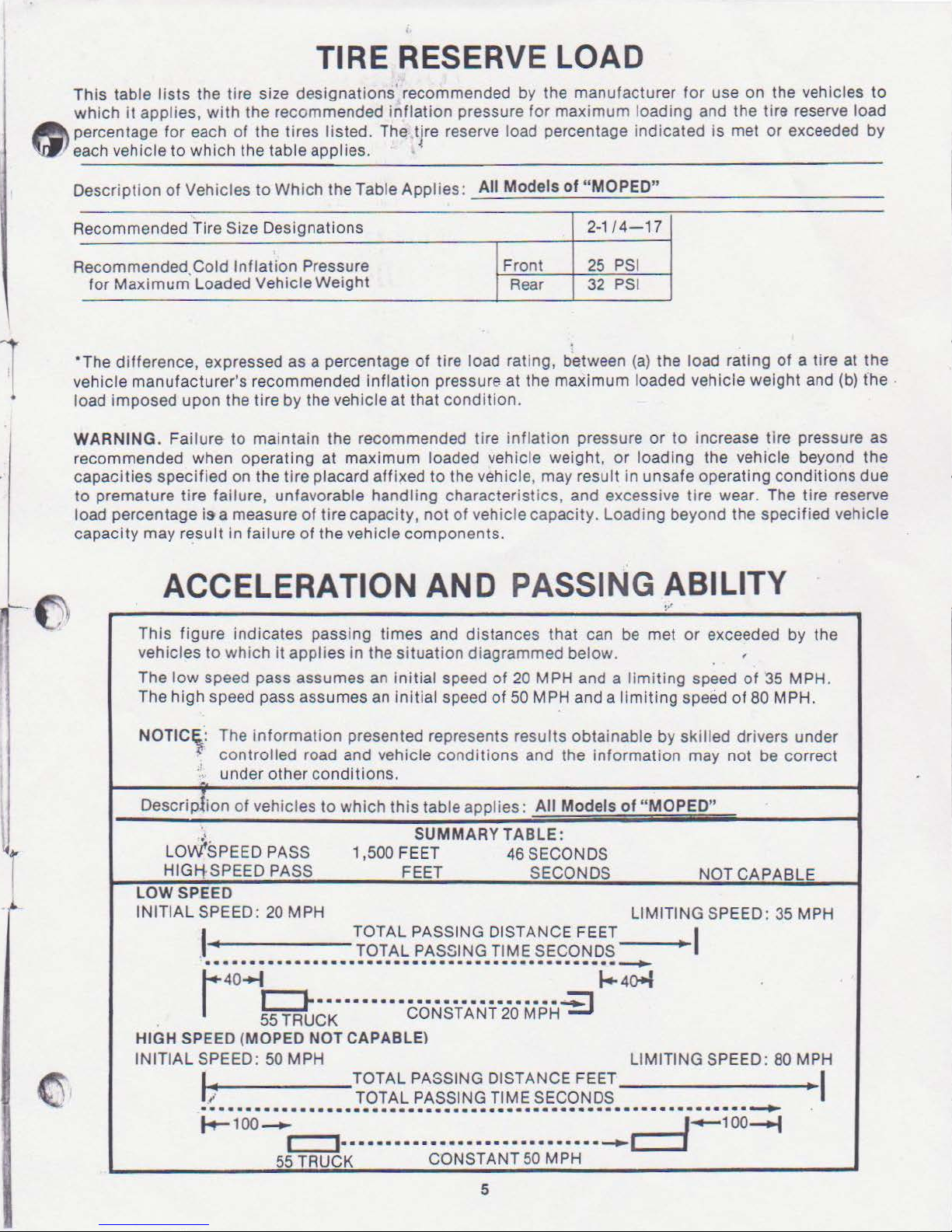
TIRE RESERVE LOAD
the tire size designations recommended by the manufacturer for use on the vehicles
with
the recom mended inflation pressure for maximum loading and the tire reserve load
for
each
of
to
which
the tires listed. The tjre reserve load percentage
the table applies.
indic
ated is met
or
exceeded by
to
Descript
ecommended Tire Size Designations
R
ecommended.Cold
R
for Maximum Loaded Vehicle Weight
*The difference, expressed as a percentage
vehicle manufacturer's recommended inflation pressure at the maximum loaded vehicle weight and (b) the .
•
load imposed
WARNING. Failure
recommended when operating at maximum loaded
capacities specified on the tire placard affixed
to
load percentage
capacity may result
ion
of
Vehicles
upon
premature tire failure, unfavorable handling characteristics, and excessive tire wear. The tire reserve
is
ACCELERATION
This figure indicates passing times and distances that can be met
vehicles
The
The high speed pass assumes an initial speed
to
low
speed pass assumes an initial speed
to
Which
Inflation
the tire by the vehicle at that
to
maintain the recommended tire
a measure
In failure of the vehicle components.
the Table Applies :
Pressure
of
tire capacity ,
_A:....:..:..:.
of
tire load rating, between (a) the load rating
condition
to
the vehicle, may result in unsafe operating conditions due
not
of
vehicle capacity. Loading beyond the specified vehicle
AND
which
it
applies
in
the situation diagrammed below.
II_M_o_;d_e_ls_of.:...
Front
Rear
.
inflation
vehicle weight, or loading the vehicle beyond the
'_;'
M~O
.:...
P-=E
2-
1/4-17
25
PSI
32
PSI
pressure
:..::
O
_"
_
__
or
to
increase
_ _
_____
of
a tire at the
tire
pressure as
_
PASSIN G ABILITY
or
of
20 MPH and a
of
50 MPH and a
limiting
limiting
exceeded
speed
speed
of
by the
'
of
35 MPH.
80 MPH.
NOTI
Cl:
The
information
. con trolled road and vehicle
·
;;
under other
Descripllon
LOW SPEED
INITIAL SPEED:
l
of
vehicles
LOWfSPEED PASS
HIGJ-tSPEED PASS
20 MPH
I
·············································-~
1 40 o
55 TRUCK CONSTANT 20 MPH
HIGH SPE
INITIAL SPEED: 50 MPH LIMITING SPEED: 80 MPH
ED
(MOPED NOT CAPABLE)
I
~
l
·····························
~
100
~
c::::J···
55 TRUCK CONSTANT 50 MPH
presented represents results obtainable by skilled drivers under
conditions
conditions.
to
which this table applies:
SUMMARY
1,500
FEE
T
FEET
TOTAL PASSING DISTANCE FEET
TOTAL PASSING TIME SECONDS
•••••••••••• ••••
TOTAL PASSING DISTANCE FEET
TOTAL PASSING TIME SECONDS
····
······
••
·
········
·
····
and the information may not be correct
All Models of "MO
TABLE:
46 SECONDS
SECONDS
PED
"
NOT
CAPABLE
LIMITING SPEED: 35 MPH
I
••••••
•
-·~
·······
··
········-~~~
1+
40+1
· · ·
·············~
100
~
I
5
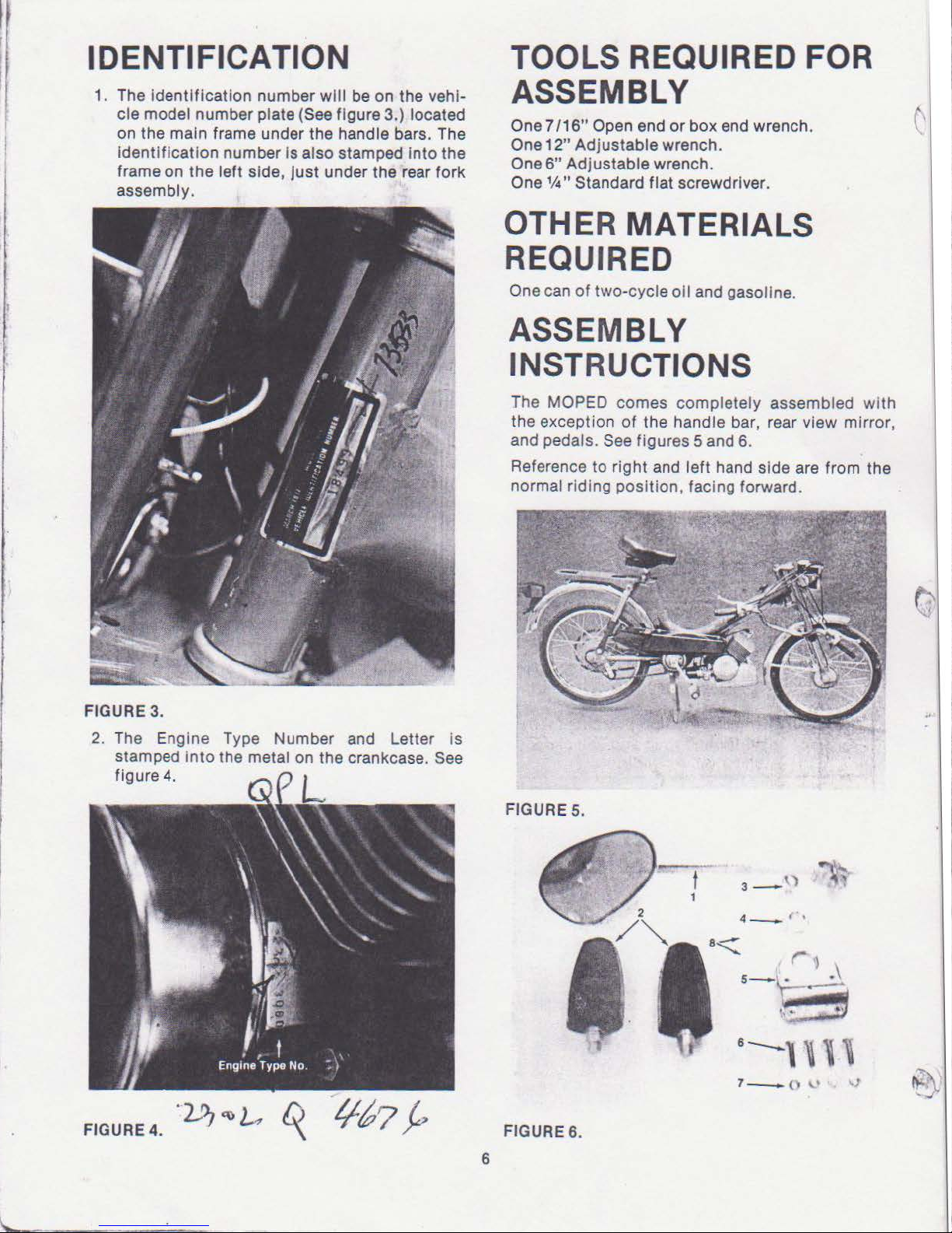
IDENTIFICATION
TOOLS REQUIRED FOR
1. The identification number
cle model number plate
on the main frame under the handle bars. The
identification number
frame on
assembly.
the
left side,
will
be on
(See figure 3.) located
is
also stamped
just
under the rear fork
the
into
vehi-
the
ASSEMBLY
One
7/16"
One
12"
One 6" Adjustable wrench.
One
Open end
Adjustable wrench.
1f4"
Standard flat screwdriver.
or
box end wrench.
OTHER MATERIALS
REQUIRED
One can
of
two-cycle oil and gasoline.
ASSEMBLY
INSTRUCTIONS
The MOPED comes completely assembled wi
the exception
and pedals.
Reference
normal riding position, faci
of
the handle bar, rear view
See figures 5 and 6.
to
right and left hand side are from the
ng
forward.
mirror
th
,
FIGURE 3.
2.
The
stamped
figure
FIGURE
4.
Engine Type Number and Letter is
into
the metal on the crankcase. See
4.
.
'2J1
~
~
~
1167
~
FIGURE 5 .
FIGURES.
6
1
t
4--..-
('
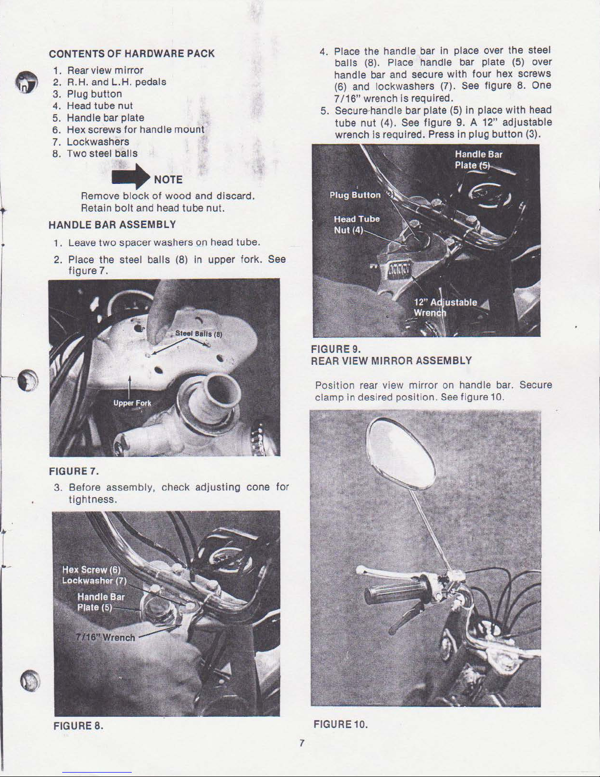
CONTENTSOFHARDWAREPACK
1. Rear view mirror
2. R.H. and L.H. pedals
3. Plug button
4.
Head tube nut
5.
Handle bar plate
6. Hex screws
for
handle mount
7. Lockwashers
8. Two steel
Remove
Retain
HANDLE BAR ASSEMBLY
balls
.NOTE
block
of
wood and discard.
bolt
and head tube nut.
4. Place the handle bar In place over the steel
balls (8). Place handle bar plate (5) over
handle bar and secure with four hex screws
(6)
and lockwashers (7).
7/16"
5.
wrench
is
required.
Secure-handle bar plate
tube nut (4).
See figure 9. A 12" adjustable
wrench is required. Press
See
figure
(5)
in place with head
8.
In plug button (3).
One
1. Leave
2.
two
spacer washers on head tube.
Place the steel balls (8) in upper fork. See
figure 7.
FIGURE 7.
3. Before assembly, check adjusting cone for
tightness.
FIGURE 9.
REAR VIEW MIRROR ASSEMBLY
Posit ion rear view mirror on handle bar. Secure
clamp
in
desired position.
See
figure 10.
FIGURE 8.
FIGURE 10.
7
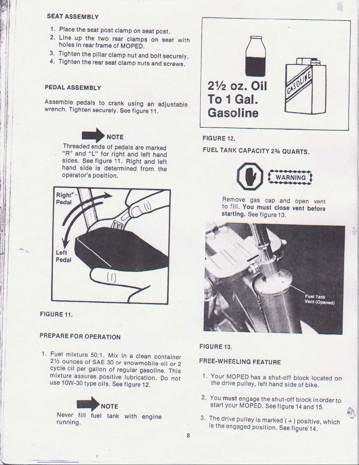
SEAT ASSEMBLY
1. Place the seat post clamp on seat post.
2.
Line
up
the
two
rear clamps
In rear frame
holes
3.
Tighten
4. Tighten the rear seat clamp
the
pillar
of
MOPED.
clamp nut and
on
bolt
nuts
and screws.
seat with
securely.
I !
I
I
PEDAL
Assemble pedals to crank using an adjustable
wrench. Tighten securely.
ASSEMBLY
See figure 11.
~NOTE
Threaded ends
"R"
and
"L"
sides.
hand
operator's
See figure 11.
side
of
pedals are marked
for
right
and
left
hand
Right
Is determined from the
position.
and
left
2V2
To
oz. Oil
1 Gal.
Gasoline
FIGURE 12.
FUEL
TANK
CAPACITY
Remove gas cap and open vent
fill.
to
starting.
You
must
See
23,4
QUARTS.
close vent before
figure 13.
FIGURE11:
PREPARE FOR OPERATION
1. Fuel mixture 50:1.
2112
ounces
cycle
mixture
use 10W-30 type oils. See figure 12.
of
oil
per gallon
assures positive lubrication. Do
SAE
Mix
30
or
of
regular gasoline. This
~NOTE
Never
running.
fill
fuel tank
in a clean container
snowmobile
with
engine
oil
or
not
2
FIGURE 13.
FREE-WHEELING FEATURE
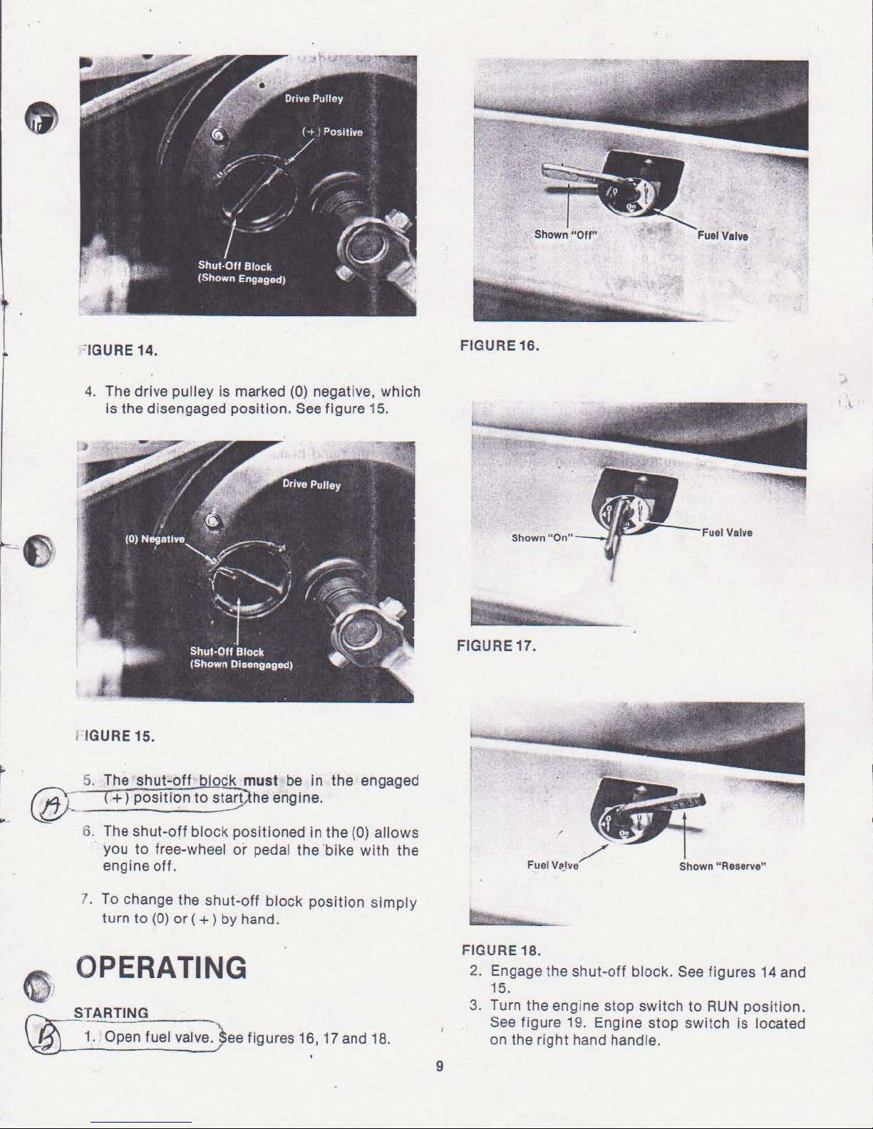
1. Your MOPED has a shutthe drive pulley, left hand side
2.
You
must
engage the
start
your
MOPED.
3.
The drive pulley
is the engaged position. See
8
See
is
marked
off
block
of
bike.
shut-off
figure 14 and 15.
block in order
(+)positive,
figure
located
which
14.
on
to
~I
=IGURE 14.
FIGURE 16.
4. The drive pulley
is
the
disengaged
IGURE 15.
is
marked (0) negative, which
position.
See
figure
15.
FIGURE 17.
6. The
7. To change the
shut-off
you
to
engine
turn
to
block
free-wheel
off.
shut-off
(0)
or
( + ) by hand.
positioned
or
pedal the 'bike
block
OPERATING
STARTING
oc;-·
Open fuel
valve.)ee
figures 16,
in
the (0) allows
with
position
17
simply
and 18.
the
FIGURE 18.
2.
3.
9
Shown "Reserve"
Engage the
15.
Turn the engine stop switch to
See
figure 19. Engine stop switch
on the
shut-off
right
hand handle.
block. See figures 14 and
RUN
position.
is
located
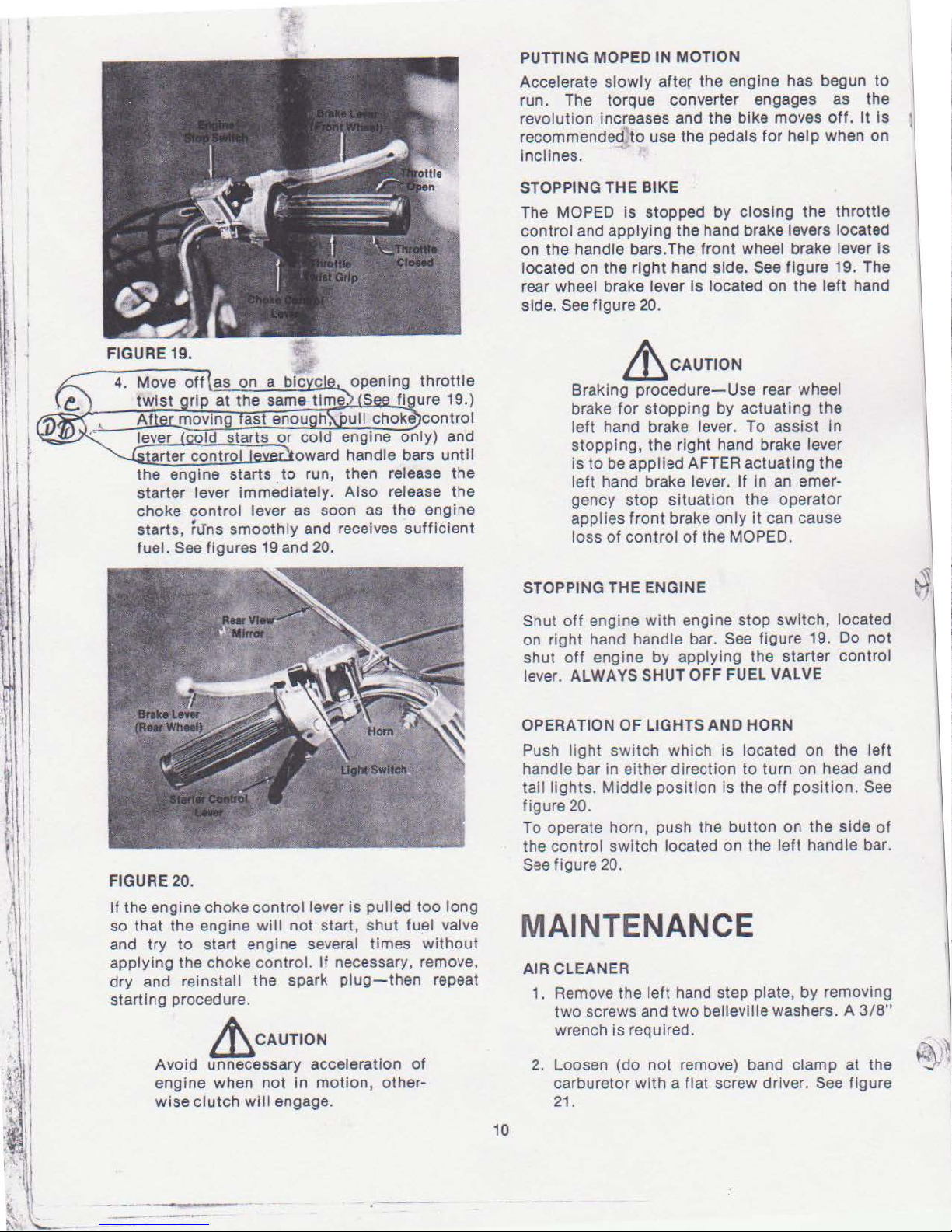
PUTTING
Accelerate
run. The torque converter engages as the
revolution increases and the bike moves
recommended
inclines.
STOPPING THE BIKE
The MOPED
control and applying the hand brake levers located
on the handle bars. The
located on the right hand side.
rear wheel brake lever
side.
MOPED IN MOTION
slowly
See figure 20.
after
to
use the pedals for help when on
is
stopped
the
engine has begun
by
closing the
front
wheel brake lever Is
See
figure 19. The
Is located on the
off.
throttle
left
hand
It
to
Is
~CAUTION
Braking
brake
left
stopping, the right hand brake lever
is
to
left
gency
applies
loss
procedure-Use
for
stopping
hand brake lever. To
be applied AFTER actuating
hand brake lever.
stop
situation
front
brake
only
of
control
of
the MOPED.
rear wheel
by
actuating the
assist
If
In
an
the operator
it
can cause
In
the
emer-
FIGURE 20.
If
the engine choke control lever
so that the engine
and try
applying the choke
dry and reinstall the spark plug- then repeat
starting procedure .
to
start engine several times
will
contr
not
ol.
is
pulled
start , shut fuel valve
If
necessary, remove,
too
long
without
~CAUTION
Avoid unnecessary acceleration
engine when
wise
clutch
not
will
in motion, other-
engage.
of
STOPPING THE ENGINE
Shut
off
engine
on right hand handle bar.
shut
off
engine by applying the starter control
lever.
ALWAYS SHUT OFF FUEL VALVE
OPERATION OF LIGHTS AND HORN
Push
li
ght
handle bar in either direction to turn on head and
taillights.
figure 20.
To operate horn, push the button on the side
the control sw itch located on the
See figure 20.
with
engine stop switch, located
See figure 19. Do
switch
Middle position is the
which
is
located on the
off
position.
left
not
left
See
of
handle bar .
MAINTENANCE
AIR CLEANER
1. Remove the
two
screws and
wrench
2.
Loosen (do not remove) band clamp at the
carburetor with a
21.
left hand step plate,
two
belleville washers. A 3/ 8"
is
required.
flat screw driver. See figure
by
removing
10
 Loading...