

Montgomery Ward ZDW-57008A, 61M-208B Owner's Manual
MOPED
Model
ZDW-570
ZDW-57061A
ZDW-57062A
Form No. ·
61M-208
Nos
08A
B*
.'
Fuel
Two Cycle
Mixture-
50
:1
.IMPORTANT
SAFE OPERATION PRACTICES
Local
licensing,
age and
traffic
regulations
may vary
from
state
to
state.
Check
existing
local
laws
.
TRAINING
1. Read
the
Owner
's
Manua
l carefully. Be
thoroughly
familiar
with
the
controls
and
proper use
of
the
equipment.
2. Never
allow
children
to
operate a MOPED
without
proper
and
close
adult
supervision.
Children
should
be
of
sufficien
t age,
understanding
and capacity.
PREPARATION
1. Check fuel before
starting
engine. Fuel
mixture
50:1 (2112
oz.
two
cycle
oil
to 1 gallon
of
regular gasoline}. Do not ·
fill
gasoline
tank
indoors, when engine
is
running,
or
while
the
engine is
still
hot.. Wipe
off any
spilled
gasoline before
starting
the engine.
2. Never
start
this
MOPED
without
being
in
proper
starting
position.
See page 9.
OPERATION
1. It is recommended the operator use a
safety
helmet
and eye protection.
2.
Manufacturer
recommends running
with
lights
on.
2
3.
It
is
the
absolute
understanding that
this
uni
t
is
not a fie
ld bike.
Any
licens
ing needed to
comply
with
the
existing
local
or
state
vehicle
requirements in
any
given area
is
the sole
responsibility
of.
the purchaser.
4. The
operator
should
never place his hands,
feet
or
any
part
of
his
body
near any moving
parts.
5.
This
MOPED is designed for ONE RIDER
ONLY. Carrier
is
not for passengers .
6.
This
MOPED
should
not
be used
in
a reckless
manner, such as
jumping
obstacles, racing
or
hill
climbing.
7.
This
MOPED is designed
for
hard surfaces,
such as pavement .
8. Never operate
this
MOPED on
wet
or
slippery
surface.
MA
INTENANCE AND STORAGE
1. Keep
all
nuts,
bolts
, and screws
tight
to
be
sure
the
unit
is
in a safe operating
con
dit
ion.
2. Never
store
the
unit
inside
of a building with
gasoline
in
the
tank where the
fumes
may
reach an open flame
or
spark.
Allow
the
engine
to
cool
before
storing
in
any
enclosure.
3.
Prior
to
each use, the
tire
pressure
should
be
checked and maintained.
Front:
25 P.S.I.,
Rear:
32
P.S .I. Maxi
mum
36
P.S.I.
front and
rear.
4. The
tightness
of
the spokes should be
checked after every few hours
of
operat ion.
See Spoke
Adjustment
on page 15.
CONTENTS
Safe Operation Practices
Index and
Cons
Tire Reserve Load
Identification
Assembly
Prepare
Operating . . . . . . . . . . . . . . . . . . . . . . . . . . . . . . . . . 9
Maintenance . .
Adjustments
Wiring
Know
umer
Information
Instructions ...
for
Operation
....................
Diagram
Your
..........
...................
........
.....
......
MOPED
.......
..........................
.......................
...............
.......
. .
................
................
. .
...............
...
.....
. .....
.........
......
. 3
...
..
.
..
...
10
. 13
... 17
KNOW YOUR MOPED
Exploded
2
Parts
Exploded
4
Parts
5
Exploded
6
Exploded View and Parts
6
Exploded View and Parts
8
E
xploded
E
xploded
Parts Ordering Procedure
View for Fork and Handle Bar
List
for
View
List for Main Frame
View
View and Parts
View and Parts
Fork and Handle Bar
for
Main Frame
for
Torque Converter
.....
................
List
for
List
for
List
for
List
for
...........
.......
...........
. . .... . .
..........
Front Wheel 24
Rear Wheel .
Controls
Engine
....
BackCover
21, 22
.....
27-31
..
..
18
. 19
20
23
25
26
FIGU
RE
1. RIGH T
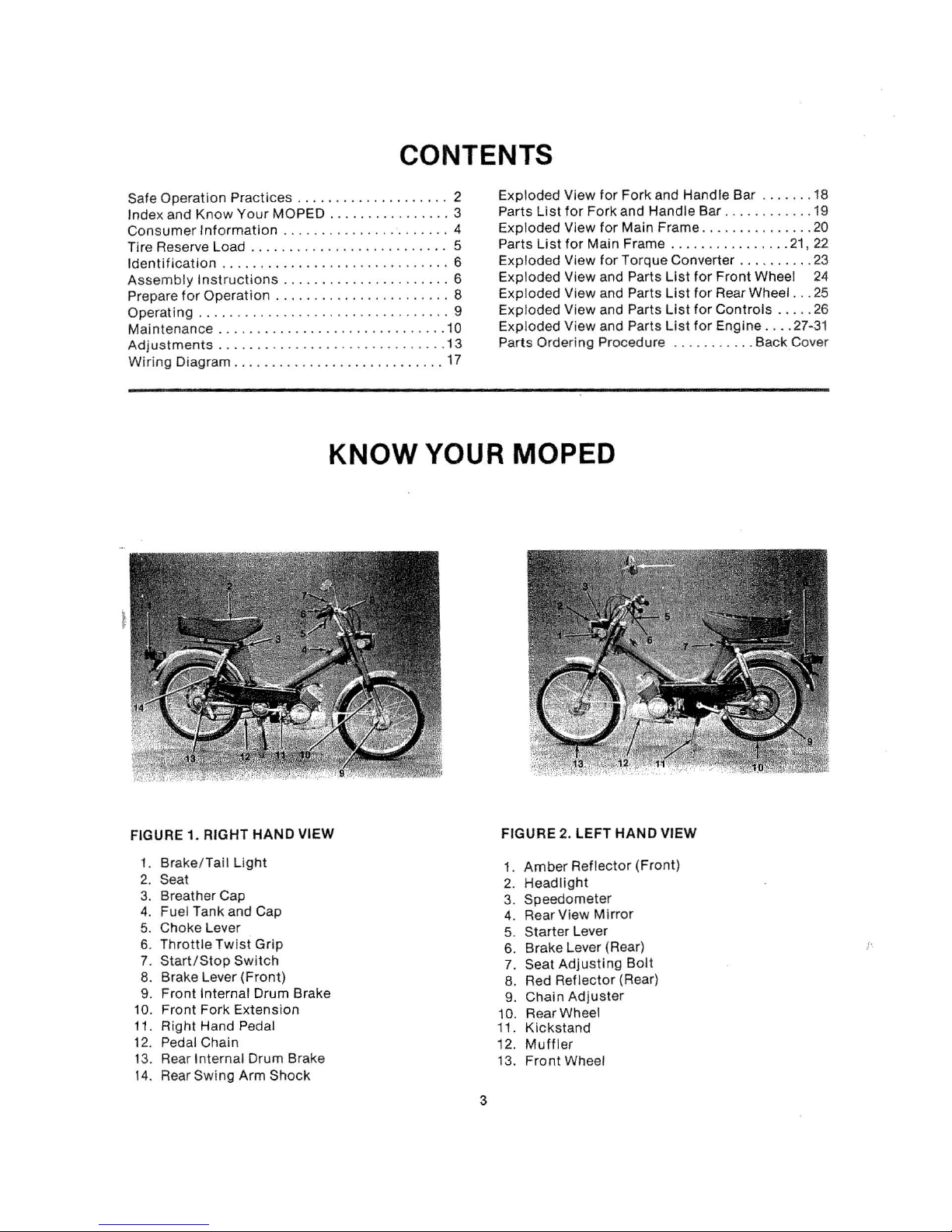
1. Brake / Tail
2.
Seat
Breather Cap
3.
4. Fuel Tank and Cap
HAND VIEW
Light
5. Choke Lever
Throttle Twist
6.
7.
Start/Stop
8. Brake Lever
9.
Front
Internal Drum Brake
10. Front Fork Extension
11.
Right
Hand Pedal
12.
Pedal Chain
Rear Internal Drum Brake
13.
Rear
14
Swing
.
Grip
Switch
(Front)
Arm Shock
FIGURE
Amber
1.
Headl ig
2.
Speedometer
3.
Rear View
4.
Starter Lever
5.
Brake Lever (Rear)
6.
Seat
7.
8.
9.
10.
11.
12.
13.
3
Adjusti
Red Reflector (Rear)
Chain
Rear Wheel
Kickstand
Muffler
Front
2. LEFT HAND VIEW
Reflector (Front)
ht
Mirror
ng
Bolt
Adjuster
Wheel
!'
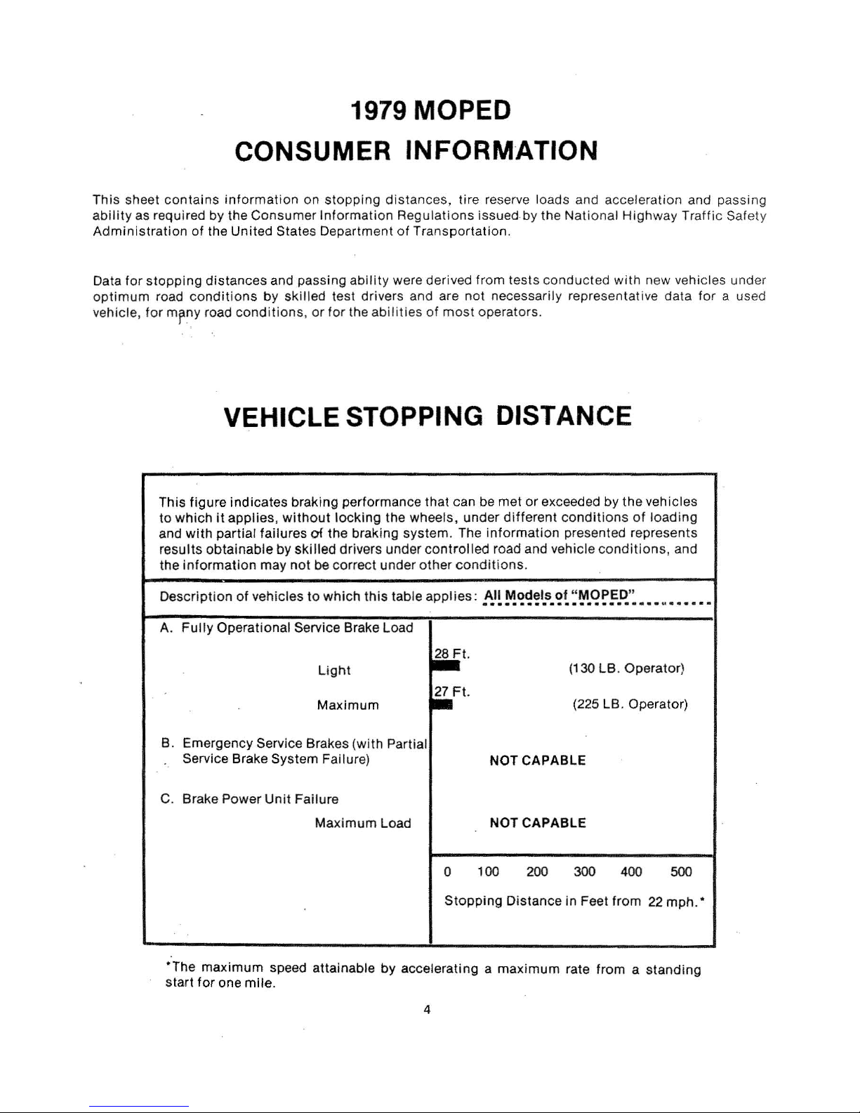
1979 MOPED
This sheet
ability
Administration
Data
optimum
vehicle,
contains
as required
tor
stopping
road
for
mrny
This figure indicates braking performance that can be met
to
which
and
results
the
CONSUMER
information
by
the Consumer
of
the
Unit
distances
conditions
road
conditions, or
on
stopp
ing
distances,
Inf
ormation R
ed
States Department
and passing
by
skilled test drivers and are
tor
ability
the
abilities
were derived from tests
INFORM
tire reserve loads and acceleration and passing
egulatio
of
Transportation.
ns issued by the
not
of
most
·ATION
conducted
necessarily repres
operators.
VEHICLE STOPPING DISTANCE
or
exceeded
it
applies,
with
partial failures
obtainable
information
by
may
without
not
locking
of
the braking system. The
skilled
drivers under
be correct under
the wheels, under
information
controlled
other
road and vehicle
conditions
different
.
National
condit
presented represents
Highwa
with
new vehicles under
enta
tive data
by
the
vehicles
ions
of
loading
conditions,
y Traffic Safety
and
for
a used
Descript
A.
B.
C. Brake Power
*The
start
ion
of
vehicles
Fully
Operational Service Brake Load
Emergency Service Brakes (with Partial
Service Brake System Failure)
Unit
maximum
for
one mile.
to
which
this
Light
Maximum
Failure
Maximum
speed attainable
table
applies:
~t
.
.Ft.
Load
0
Stopping
by
accelerating a maxi
All Models of "
••••••••••••••••••••••••
NOT
CAPABLE
NOT CAPABLE
100
200 300 400
Distance
mum
MOPED
(130 LB. Operator)
(225 LB. Operator)
in
Feet
rate
"
M
aaaaaa
500
from
22
mph.
from a standing
•
4
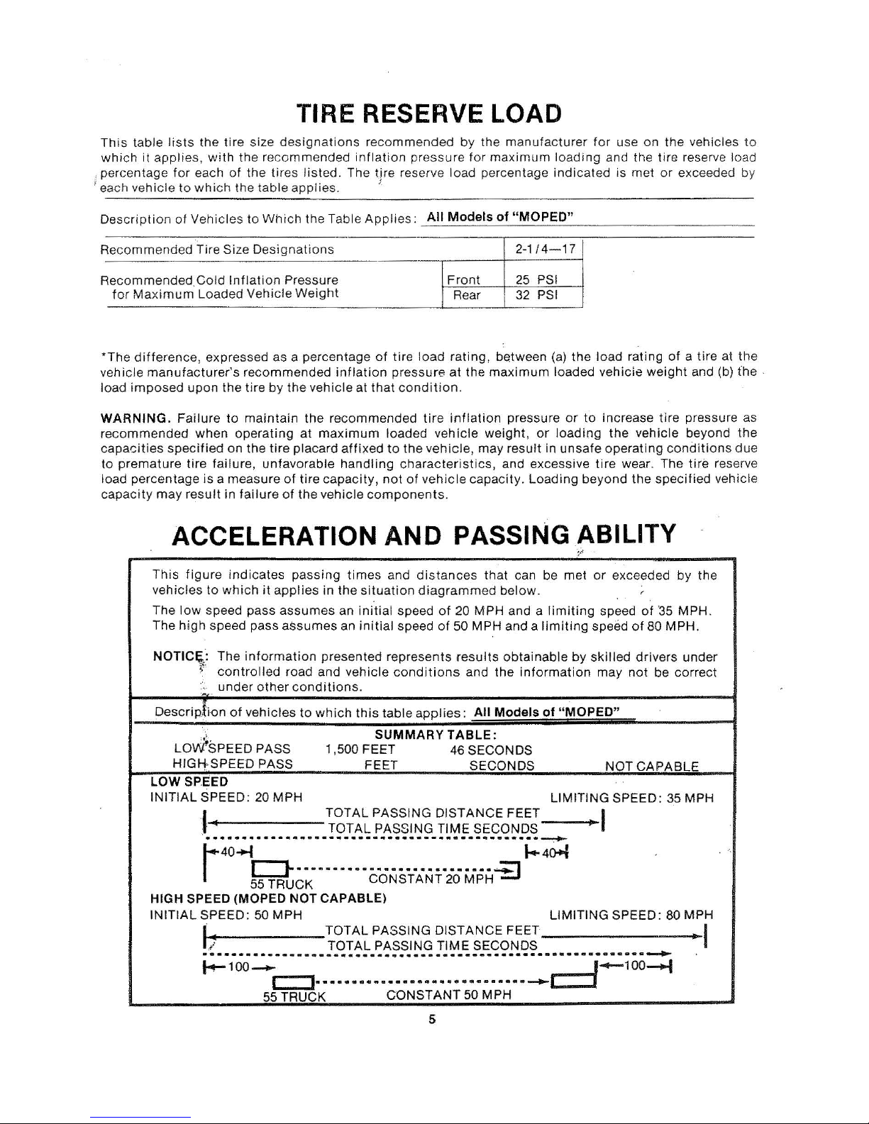
TIRE RESERVE LOAD
Th
is
table
lists the
tire
size
designations
recommended
by
the
manufacturer
for
use
on
the
vehicles
to
which
it
applie
s,
with
the
recommended inflation pressure
tor
maximum
loading
and
the
tire reser
ve
load
, percentage f
or
each
of
the tires
listed. The
tire
reserve load percentage
indicated
is
met
or
exceeded
by
1
eac h ve
hicle
to
which
the tab
le
applies.
:
Descr
ipt
ion
of
Vehicles
to
Which the
Table
Appl
ies:
_A_II
_M_
o_d
_e_l_s_o_f_
"_M_O_P_E
_D_"
__
_
__
_
__
__
_
-
R
ecommended
Tire Size
Designations
2-1/4-17
-
R
ecommended. Cold
Inflati
on Pressu
re
Front
25 PSI
for
Maximum Loaded Vehi
cle
Weight
Rear 32 P
SI
*
The
difference,
expressed as a
percentage
of
tire
load rating,
between (a)
the
load
rating
of
a tire at
the
ve
hicle
manufacturer's
recommended
inflation
pressure
at
the
maximum loa
ded
vehicie
weight
and (b)
the
·
load imposed upon
the
tire
by
the
vehi
cle
at
that
condition.
WARNING. Failu
re
to
maintain
the
recommended
tire
inflation
pressure
or
to
increase
tire
pres
sure
as
recom
mended
when
operating
at max
imum
loaded
vehicle
weight,
or
load i
ng
the
vehicle beyond
the
capacities
specified
on
the
tire
placard
affixed
to
the
vehicle, may
result
in
unsa
fe
operating
conditions
due
to
premature
tire
failur
e,
unfav
orable
handling
characteristics,
and e
xcessive
tir
e wear.
The
tire
reserve
load perce
ntage
is
a meas
ure
of
tire
capacity,
not
of
vehicle
capacity.
Loadi
ng
beyond
the
specified
vehicle
capaci
ty
may result in
failure
of
the
vehicle
components.
ACCELERATION
AND
PASSING ABILITY
This
figure
indicates
passing
times
and
distan
ces
that
can
be
met
or
exceeded
by the
ve
hicl
es
to
which
it
applies
in
the
situation
diagrammed
below.
. .
r
The
low
speed
pass
assumes
an
initial
speed
of
20
MPH
and a
limiting
speed
of
'35
MPH
.
The
hi
gh speed pass
assumes
an
initial
speed
of
50
MPH
and a
limiting
speed
of
80
MPH.
NOTIC~:
The
info
rmation
presented
represe
nts
results
obt
ainable by
skilled
drivers
under
~;
controlled
road and
vehicle
cond
itions
and
the
information
may
not
be
corre
ct
..
under other
cond
ition
s .
Desc
rip
.\i
on
of vehicles
to
which
this
table
app
lie
s:
All
Models
of
"MOPED"
LOviSPEED
PASS
SUMMARY
TABLE:
1,500
FEET
46
SECONDS
HIG!i
·SPEED PASS
FEET
SECONDS
NOT CAPA
BLE
LOW
SP.EED
INITIAL
SPEED
: 20
MPH
LIMITING
SPEED:
35
MPH
I
TOTAL
PASSING
DISTANCE
FEET
I
TOTAL
PASSING
TIME
SECONDS
·······························-·············-~
r40b·-····
·····
······
·
·········~
t-.4~
55 TRUCK
CONSTANT
20
MPH
HIGH SPEED (MOPED NOT
CAPABLE)
INITIAL SPEED:
50
MPH
LIMITING
SPEED:
80
MPH
L~
TOTAL
PASSING
DISTANCE
FEET
I
TOTAL
PASSING
TIME
SECONDS
····························································-~
~100~
r::::l·····
·····
···· ····
·····
-
·····~~~100~
55
TRUCK
CONSTANT
50
MPH
5
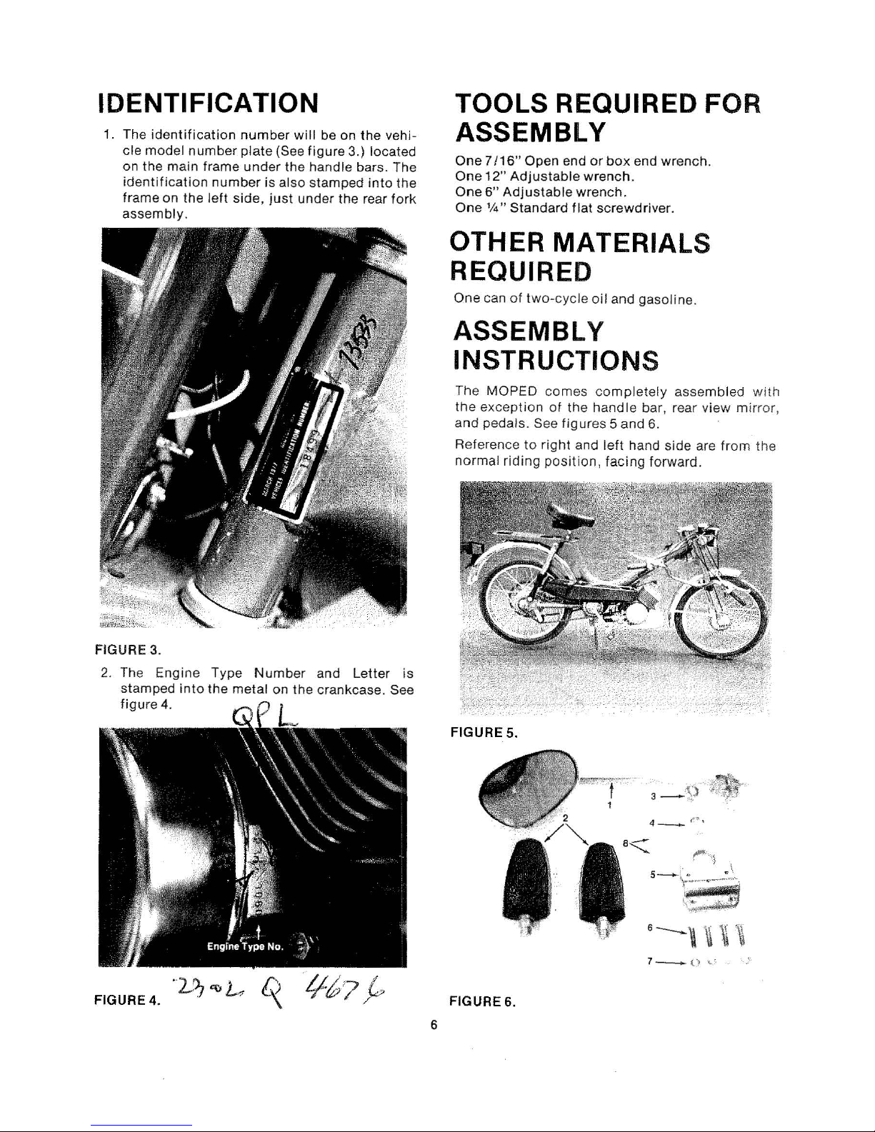
IDENTIFICATION
1.
The
identification
cle model
on
the
identifi
frame on the
assembly.
number
main
cation
frame
number
left
side,
number
plate (See
under
will
the
is also stamped
just
under
figure
handle bars. The
be
on
the rear
3.)
the
locat
into
vehi-
ed
the
fork
TOOLS REQUIRED FOR
ASSEMBLY
One
7/16"
One
One
One
Open end
12"
Adjustable
6"
Adjustable
1f4"
Standard
or box end wrench.
wrench.
wrench.
flat
screwdriver.
OTHER MATERIALS
REQUIRED
One
can of t
wo-cyc
le
oil
and gasoline.
ASSEMBLY
INSTRUCTIONS
FIGURE 3.
2. The Engine Type
stamped
figure
4.
into
the
Number
metal
on
and
Letter
the
crankcase. See
is
The MOPED
the
exception
and
pedals
Reference
normal
FIGURE 5.
riding
comes
of
. See
figures 5 and
to
right
position,
completely
the
handle
and
left
hand
facing
assembled
bar, rear
6.
side
forward.
view mirror
are
from
with
,
the
'2 ..
FIGURE 4. •
f).
'.J
"ttL
/:)
~
FIGURE 6.
6
7-
o
~·
. __ ,.
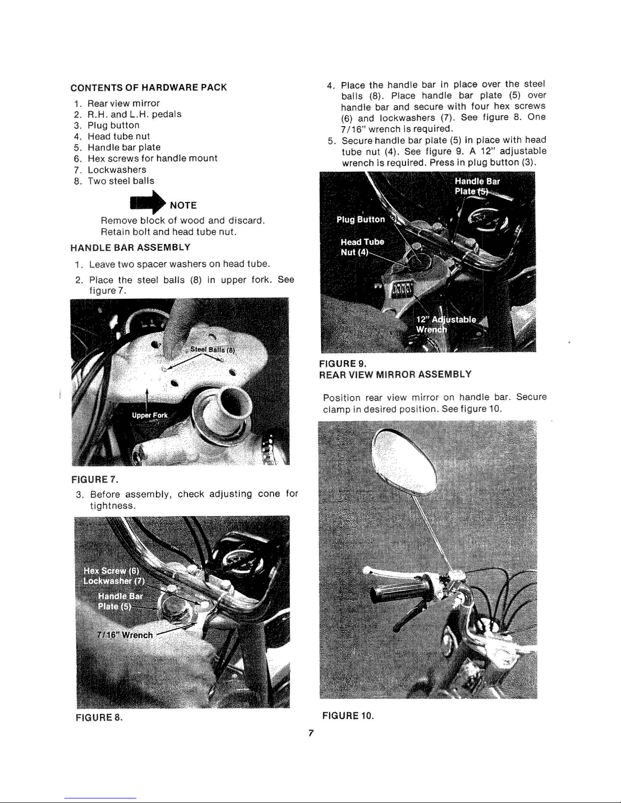
CONTENTS
1.
Rear view
2.
R.H.
3.
Plug
4. Head
5.
Handle
6. Hex
7.
Lockwashers
Two
8.
OF
mirror
and
L.H
button
tube
bar plate
screws
steel
balls
HARDWARE PACK
. pedals
nut
for
handle
.._,NOTE
Remove
Retain
block
bolt
of
wood
and head
HANDLE BAR ASSEMBLY
1.
Leave
two
2.
Place
figure?.
spacer
the
steel balls
washers on head
mount
and
discard.
tube
nut.
tube.
(8) in upper fork. See
4. Place
5.
the
handle bar In place over
balls
(8). Place handle bar
handle
(6) and
7/ 16"
Secure
tube
wrench
bar and secure
lockwashers (7). See f
wrench
nut (4). See figure
Is required.
handle
is
requi red. Press
FIGURE 9.
VIEW MIRROR ASSEMBLY
REAR
plate
with
four
hex screws
igur
bar plate (5) in place
9. A 12"
in
plug
button
the
steel
(5) over
e 8. One
with
head
adjustab
(3).
le
FIGURE 7.
3.
Before assem
tightness.
bly,
check
adjusting
cone
for
Position
clamp
rear view
in desired
mirror
position.
on handle bar. Secure
See
figure 10.
FIGU
RE
8.
FIGURE
7
10
.
SEAT ASSEMBLY
1. Place
the
seat
post
clamp
on
seat
post.
2. Line
up
the
two
rear
clamps
on
seat
with
holes
in
rear frame
of
MOPED.
3.
Tighten
the
pillar
clamp
nut
and
bolt
securely.
4.
Tighten
the
rear seat
clamp
nuts
and screws.
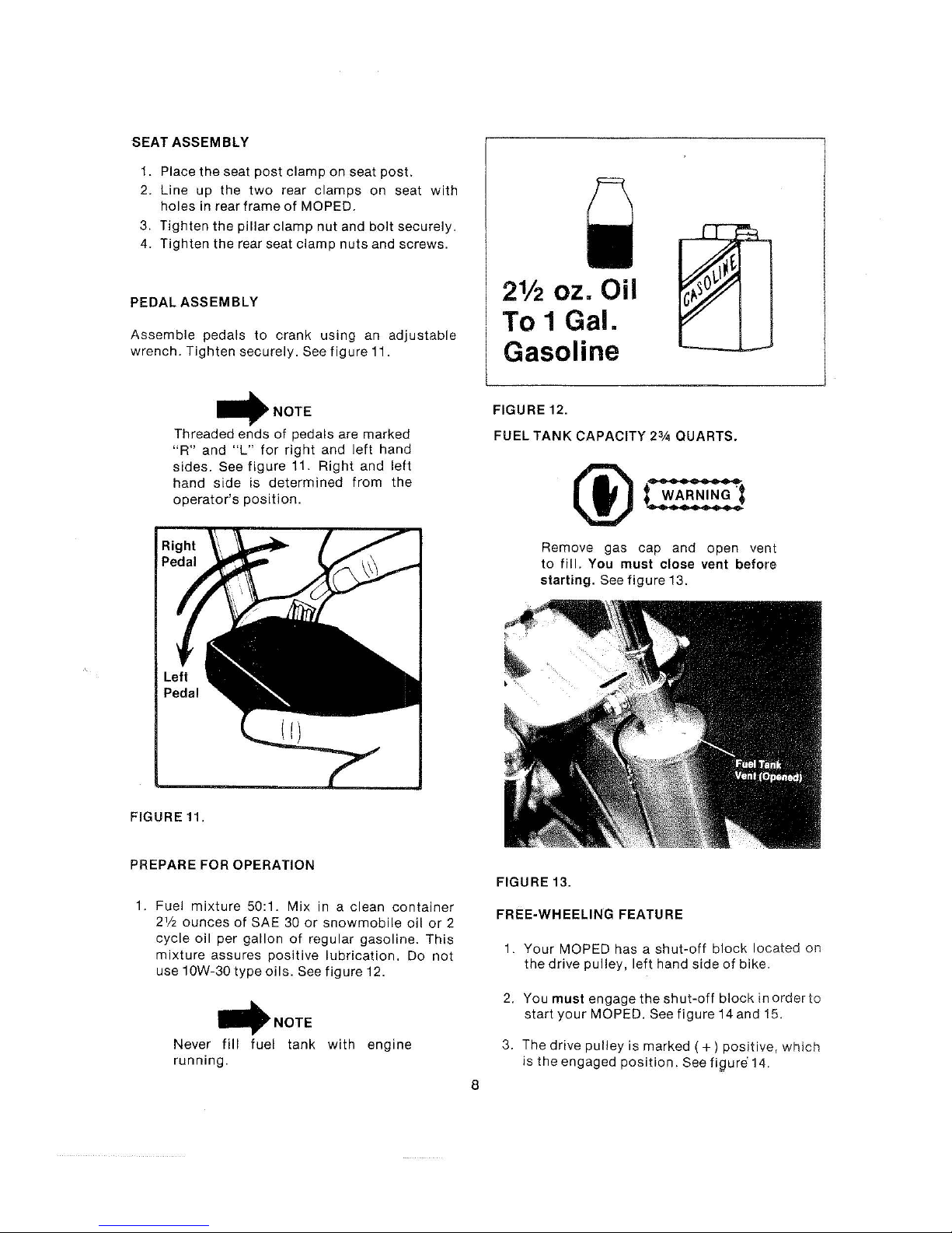
PEDAL
ASSEMBLY
Assemble
pedals
to
crank
using
an
adjustable
wrench.
Tighten
securely.
See
figure
11.
~NOTE
Threaded ends
of
pedals are marked
"R"
and
"L"
for
right
and
left
hand
sides.
See
figure
11.
Right
and
left
hand
side
is
determined
from
the
operator
's
position.
FIGURE 11.
PREPARE FOR OPERATION
1. Fuel
mixture
50:1.
Mix
in a clean
container
2112
ounces
of
SAE 30
or
snowmobile
oil
or
2
cycle
oil
per
gallon
of
regular
gasoli
ne.
This
mixture
assures
positive
lubrication.
Do
not
use 10W-30
type
oils.
See
figure
12.
~NOTE
Never
fill
fuel
tank
with
engine
running.
8
21/2
oz. Oil
To 1 Gal.
Gasoline
FIGURE 12.
FUEL
TANK
CAPACITY
2%
QUARTS.
Remove gas cap and ope n vent
to
fill.
You
must
close
vent
befor
e
starting.
See
figure
13.
FIGURE 13.
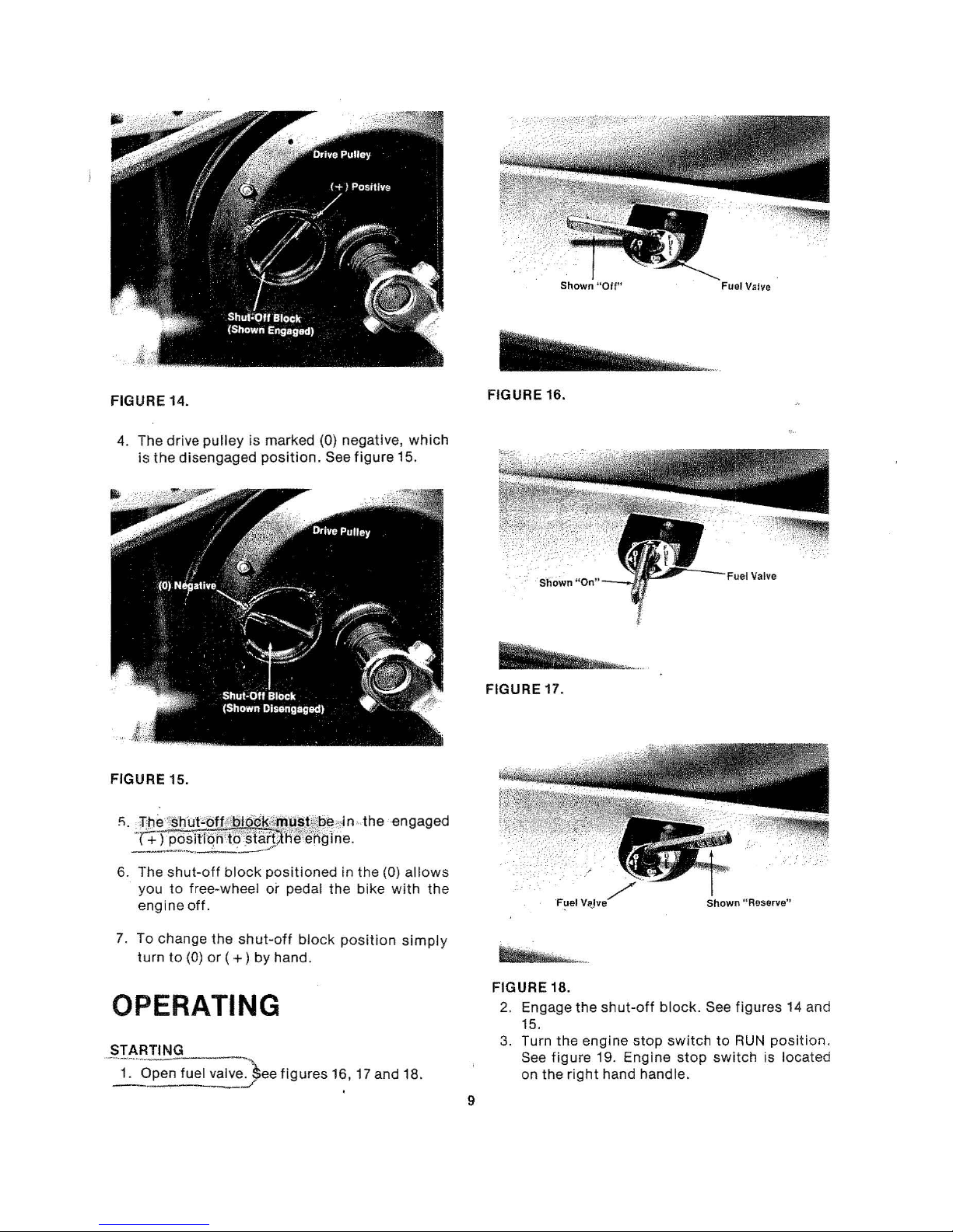
FREE-WHEELING FEATURE
1.
Your
MOPED has a
shut-off
block
located
on
the dr
ive
pulley, left
hand side
of
bike.
2. You
must
engage
the
shut
-off
block
in order
to
start your
MOPED. See f
igure
14 and 15.
3. The drive
pulley
is
marked ( + )
posit
ive,
which
is
the
engaged
position.
See fifJure 1
4.
Shown "
Off"
Valve
FIGURE
4. The drive
FIGURE 15.
~.
is
the
:p
!~'~
14.
disengaged
pulley
!~;~
is
marked (0) negative,
position.
lf~~~~
See
mf
ri~··
figure
the
FIGURE 16.
which
15.
FIGURE 17.
engaged
6. The
7. To change
shut-off
you
to
engine
turn
to
block
free-wheel
off.
the
shut-off
(0)
or
(
+)
positioned
or
pedal
block
by hand.
OPERATING
STARTING
--·1:---o;;;;~uel
- -
v;,:')ee
../
figures
in
the
(0)
allows
the
bike
with
position
16, 17 and 18.
simpl
the
y
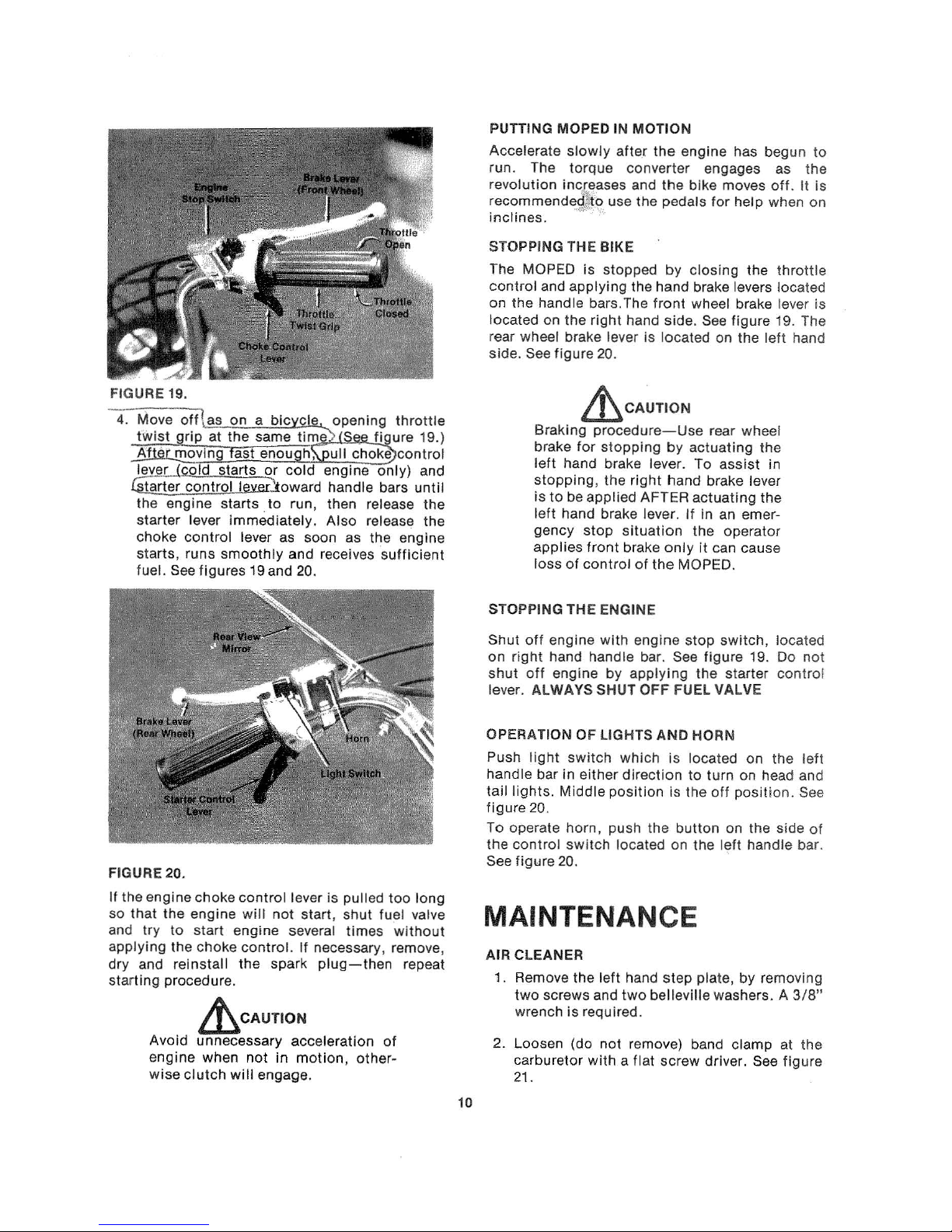
FIGURE 18.
2. Engage
3.
9
15.
Turn the
See
figure
on the
right
the
shut-off
engine
19
. Engine
hand handle.
stop
block.
switch
stop
Shown
~~Reserve"
See figures 14 and
to
RUN
position
switch
is
locat
ed
.
PUTTING MOPED IN MOTION
Accelerate
run. The torque converter engages as
revolution increases and
recommendej:i() use the pedals
inc
lines.
slowly
··
···
after
the
engine has begun
the
bike moves
for
help when on
off.
the
It
to
is
FIGURE 19.
4:
-Move
Gi_a
off
l as
twist
grip
At
···
·moving
ley~r
(cold starts
rter £Q!l!IQ.Llwer)oward handle bars
the engine starts .
starter
choke
starts, runs
fuel. See
lever
control
figures
on
a bicyctg, opening
at
the
same time'> S
fast
enou h, ull choke
or
cold
engine
to
run, then release
immediately.
lever as soon as the engine
smoothly
19
and 20.
Also
and receives
release the
throttle
figure
19.)
control
only)
and
until
sufficient
the
STOPPING
The MOPED
control
on
the
located on
rear wheel brake lever is located on
side.
THE BIKE
is
stopped
and applying the hand brake levers located
handle bars.The
the
right
See
figure
20.
by closing
front
wheel brake lever
hand side. See
~CAUTION
Braking
brake
left
stopping,
is
left
gency
applies
loss
STOPPING THE ENGINE
Shut
off
on
right
shut
off
lever. ALWAYS SHUT
procedure-Use
for
stopping
hand brake lever. To
the
to
be
applied
hand brake lever.
stop sit
front
of
control
engine
hand handle bar. See
engine
with
by
by
right
hand
AFTER
uat
ion
brake
only
of
the
engine
applying
OFF
If
MOPED.
stop
FUEL VALVE
rear wheel
actuating
assist
brake lever
actuating
in
an emer-
the
it
can cause
figu
the
the
figure
the
left hand
the
in
the
operator
switch,
re
19. Do not
starter
throttle
is
19. The
located
contro
l
FIGURE20.
If
the engine c
so
that
and
try
applying
dry and
starting procedure.
Avoid unnecessary acceleration
engine
wise
hoke
control
the engine
to start engine several
the
reinstall
clutch
will
not
choke
control.
the
spark plug- then repeat
~CAUT
when
will
I
not
in
engage.
ON
lever is pulled
start, shut fuel valve
If
necessary, remove,
motion
too
times without
of
, other-
long
OPERATION OF LIGHTS AND HORN
Push
lig
ht
switch which
handle bar
tail
lights.
figure
To operate horn, push the
the
control
See
in
Middle
20.
switch
figure 20.
either
position
direction
located on
MAINTENANCE
AIR CLEANER
1.
Remove
two
wrench is required.
2. Loosen (do
carburetor
21.
10
the
left hand
screws and
not
with a fla
step
two
belleville washers. A 3/
remove) band clamp at
t screw driver. See
is located
to
turn on head and
Is the
off
position
button
on the side of
the
l~ft
plate,
on
the l
. See
handle bar.
by
removing
figure
eft
8"
the
 Loading...