

Page 1

Page 2

Safe Operation Practices
Assembly Instructions. .
Controls. Operation. Adjustments Lubrication. Maintenance Off-Season Storage.
...3 Trouble Shooting Chart. ...4 Electrical System. ...9 Illustrated Parts for Rider. ...
22,24,26,28,3023,25,27,29,31
..11 Parts List for Rider ..12 Illustrated Parts for Transaxles
32,34
..14 Parts List forTransaxles ..14 Parts Information ..18
NOTICE: A data plate with the model number and serial numbers of your unit is located on the frame,
under the seat. Record these numbers in the spaces provided on the back cover of this guide.
33,35
Back Cover
19
21
This
~ WARNING:
unit is equipped with an internal combustion engine and should not be used on or near any unimproved forest-covered, brush-covered or grass-covered land unless the engine's exhaust system is
equipped with a spark arrester meeting applicable local or state laws (if any). If a spark arrester is used, it
should be maintained in effective working order by the operator.
In the State of California the above is required by law (Section 4442 of the California Public Resources
Code). Other states may have similar laws. Federal laws apply on federal lands. A spark arrester muffler is
available at your nearest engine authorized service center.
2
Page 3
(t) :C~~~EI~Ej
To reduce the potential for any injury, comply with the following safety instructions. Failure to comply
with the instructions may result in personal injury.
SAFE OPERATION PRACTICES FOR RIDING VEHICLES
1. Read this owner's manual carefully in its en- 16. Disengage power to attachment(s) and stop
tirety before attempting to assemble or engine before making any repairs or adoperate this unit. Keep this manual in a safe justments. Disconnect the spark plug wire
place for future and regular reference and for and keep the wire away from the plug to preordering replacement parts. vent accidental starting.
2. This unit is a precision piece of power equip- 17. Before attempting to unclog the mower or
ment, not a plaything, Therefore exercise ex- discharge chute, stop the engine. The mower
treme caution at all times. blade(s) may continue to rotate for a few
3. Know the controls and how to stop quickly- seconds after the engine is shut off.
READ THIS OWNER'S MANUAL. Therefore, be sure the blade(s) have stopped
4. Do not allow children to operate vehicle. Do completely. Disconnect the spark plug wire
not allow adults to operate it without proper and keep the wire away from the plug to preinstruction. Only persons well acquainted vent accidental starting.
wit!! these rules of safe operation should be 18. Disengage power to attachment(s) when
allowed to use your mower. transporting or not in use.
5. ~o one sho~ld op.erate th,is u.nit whil~ int'?x- 19. Take all possible precautions when leaving
Icated or while takl~g medication that Impairs vehicle unattended such as disengaging
the senses or reactions. power-take-off, lowering attachments, shift-
6. Wear ~t~rdy, rough-soled work shoe~ and ing into neutral, setting parking brake, stopclose-fitting slacks and shirts to avoid en- ping engine and removing key
tanglement in the moving parts. Never operate .i
a unit in bare feet, sandals, or sneakers. 20. Do ,not stop or, start suddenly when go ng
7. To prevent injury, do not carry passengers or uphill or dow.nhili. Mow up and down face of
give rides. Keep children, pets and by- steep slop~s, ~e~er. across the face. l:'se exstanders out of the area while mowing. Only treme cautlo~ If .It IS necessary to drive th~
the operator should ride on the unit and only trac.tor ~p an Incline or back the tractor dow
r'de in the seat an Incline because the front of the tractor
8. ~heck overhea.d clearance carefully before could lift and raJ;>idly !Iip over backward which
driving under power lines, guy wires, bridges could cause serious Injury.
or low hanging tree branches, before entering 21. Reduce speed on slopes and in sharp turns to
or leaving buildings, or in any other situation prevent tipping or loss of control. Always
where the operator may be struck or pulled keep the tractor in gear when going down
from the unit, which could result in serious in- steep hills to take advantage of engine brak.
jury. ing action.
9. To maintain control of the unit and reduce the 22. Stay alert for holes in terrain and other hidden
possibility of upset or collision, operate the hazards.
tractor .smoothly. Avoid erratic operation and 23. Use care when pulling loads or using heavy
excessive speed.. equipment.
10. Keep the ~rea of operation .clear of all per- A, Use only approved drawbar hitch points.
sons, particularly small children and pets. B Limit loads to those you can safely control,
Stop engine when they are in the vicinity. of C: Do not turn sharply. Use care when back.
your mower. Although the area of oP.eratlon ing.
.should be comple.tely cleared of foreign ob. D. Use counterweight(s) or wheel weights
Jects, a small object ~ay have been over. when suggested in owner's manual.
looked and could be accidently thrown by the ..
mower in any direction and cause injury. 24. Watch out for traffic when crossing or near
11. Clear work area of objects which might be roadways.
picked up and thrown by the mower in any 25. When using any a~tachments, never direct disdirection and cause injury. charge of material t?ward ~y~tanders .nor
12. Stop the blade(s) when crossing gravel drives, allow anyone near vehicle while In operation.
walks or roads. 26. Handle gasoline with care. It is highly flam-
13. Disengage all attachment clutches and shift mable,
into neutral before attempting to start engine. A. Use approved gasoline container.
14. Disengage power to attachment(s) and stop B. Never remove cap or add gasoline to a runengine before leaving operating position. ning or hot engine or fill fuel tank indoors.
15. Do not put hands or feet near or under rotating Wipe up spilled gasoline.
parts. Keep clear of the discharge opening at C. Open doors if engine is run in garage. Ex.
all times as the rotating blade(s) can cause in- haust fumes are dangerous. Do not run
jury. 3 engine indoors.
Page 4
27. Keep the vehicle and attachments in good
operating condition, and keep safety devices
in place. Use guards as instructed in
operator's manual.
28. Keep all nuts, bolts, and screws tight to be
sure the equipment is in safe working condi-
tion.
29. Never store the equipment with gasoline in
the tank inside a building where fumes may
reach an open flame or spark. Allow engine to
cool before storing in any enclosure.
30. To reduce fire hazard, keep engine free of
grass, leaves or excessive grease.
31. The vehicle and attachments should be
stopped and inspected for damage after strik-
ing a foreign object. The damage should be
repaired before restarting and operating the
equipment.
32. Do not change the engine governor settings
or overs peed the engine.33.
When using the vehicle with mower, proceed
as follows:
(1) Mow only in daylight or in good artificial
light.
(2) Never make a cutting height adjustment
while engine is running if operator must
dismount to do so.
(3) Shut the engine off and wait until the
blade comes to a complete stop before
removing the grass catcher.
(4) Check blade mounting bolts for proper
tightness at frequent intervals.
34. Check grass catcher bags frequently for wear
or deterioration. For safety protection, replace
only with new bag meeting original equipment
specifications.35.
Look behind to make sure the area is clear
before placing the transmission in reverse
and continue looking behind while backing
up. Disengage blades before shifting into
reverse and backing up.
36. This unit should not be driven up a ramp onto
a trailer or truck under power, because the
unit could tip over, causing serious personal
injury. The unit must be pushed manually to
load properly.
NOTE
This unit is shipped WITHOUT GASOLINE or OIL. After assembly, see
separate engine manual for proper
fuel and engine oil recommendations.
A_' ~ --J -fr
B--I;::;. K ~'
C-@ -f('
D--_~ ~ F
~r -.,~~ ~ r
H
~;:~~ 1
FIGURE 1.
ASSEMBLY
NOTE
Reference to right hand or left hand
side of machine is from the operat-
ing position, facing forward.
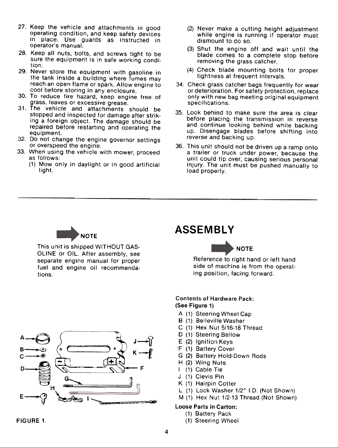
Contents of Hardware Pack:
(See Figure 1)
A (1) Steering Wheel Cap
B (1) Belleville Washer
C (1) Hex Nut 5/16-18 Thread
0 (1) Steering Bellow
E (2) Ignition Keys
'F (1) Battery Cover
G (2) Battery Hold-Down Rods
H (2) Wing Nuts
I (1) Cable Tie
J (1) Clevis Pin
K (1) Hairpin Cotter
L (1) Lock Washer 1/2" 1.0. (Not Shown)
~
M (1) Hex Nut 1/2-13 Thread (Not Shown)
Loose Parts in Carton:
(1) Battery Pack
(1) Steeri ng Wheel
E-')J
4
Page 5
BATTERY INFORMATION
~ ~A_R~I_N? -_t
Battery acid must be handled with great care
as contact with it can burn and blister the skin.
It is also advisable to wear protective clothing
(goggles, rubber gloves and apron) when work-
ing with it..
B. Should battery acid accidentally splatter into
the eyes or onto the face, rinse the affected
area immediately with clean cold water. If
there is any further discomfort, seek prompt
medical attention.C.
If acid spills on clothing, first dilute it with
clean water, then neutralize with a solution of
ammonia/water or baking soda/water.
Since battery acid is corrosive, do not pour it
into any sink or drain. Before discarding empty
electrolyte containers, rinse :hem with a
neutralizing solution.E.
NEVER connect or disconnect charger clips to
battery while charger is turned on as it can
cause sparks.
F. Keep all lighted materials (cigarettes, match-
es, lighters) away from the battery as the
hydrogen gas generated during charging can
be combustible.G.
As a further precaution, only charge the battery
in a well-ventilated area.
.Always shield eyes, protect skin and clothing
when working near batteries.
ACTIVATING AND INSTAlliNG THE BATTERY
1. Upon opening the battery pack, you should
receive acid pack, battery, drain tube, filling
adapter and i}9rdware.
WARNING;
FIGURE 2.
FIGURE 3.
BATTERIES CONTAIN SULFURIC
ACID AND MAY CONTAIN EXPLOSIVE GASES (when electrolyte has
been added).
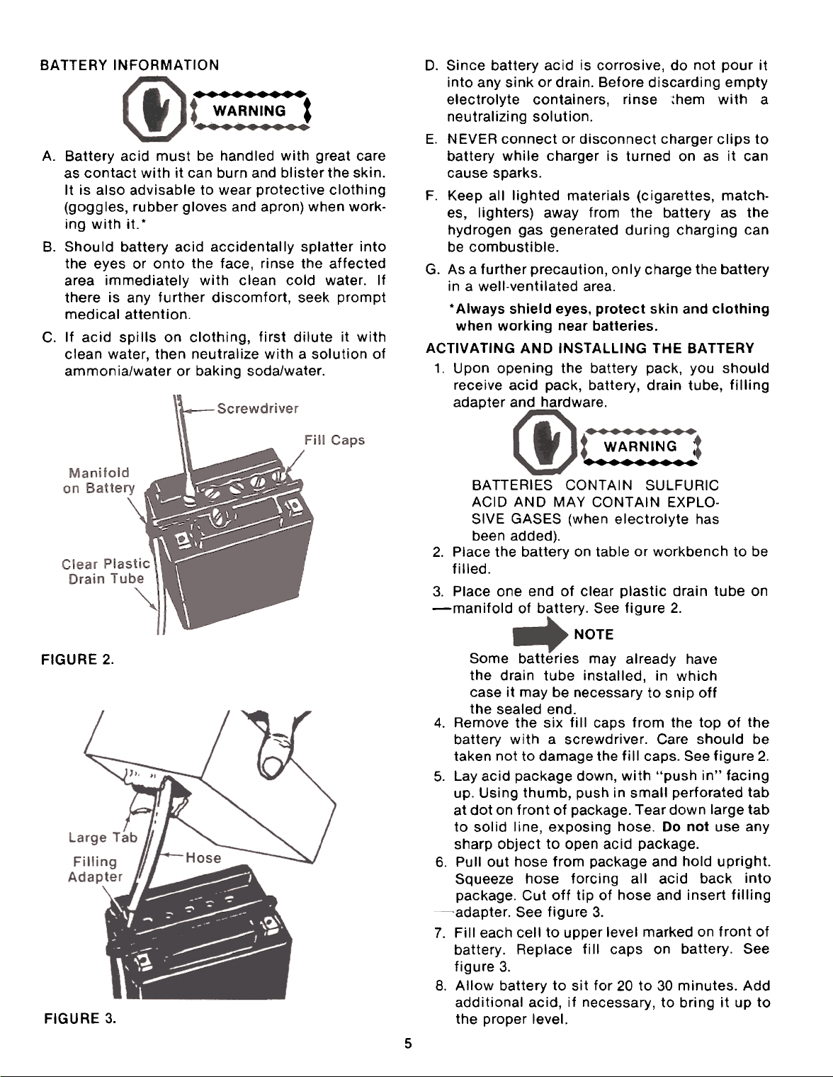
2. Place the battery on table or workbench to be
filled.3.
Place one end of clear plastic drain tube on-manifold
of battery. See figure 2.
NOTE
Some batteries may already have
the drain tube installed, in which
case it may be necessary to snip off
the sealed end.
4. Remove the six fill caps from the top of the
battery with a screwdriver. Care should be
taken not to damage the fill caps. See figure 2.
5. Lay acid package down, with "push in" facing
up. Using thumb, push in small perforated tab
at dot on front of package. Tear down large tab
to solid line, exposing hose. Do not use any
sharp object to open acid package.
6. Pullout hose from package and hold upright.
Squeeze hose forcing all acid back into
package. Cut off tip of hose and insert filling~adapter.
See figure 3.
7. Fill each celt to upper level marked on front of
battery. Replace fill caps on battery. See
figure 3.
8. Allow battery to sit for 20 to 30 minutes. Add
additional acid, if necessary, to bring it up to
the proper level.
D.
A.
5
Page 6
Battery contains sulfuric acid. Refer to warning on
page 5. Antidote: EXTERNAL-Flush with water.
INTERNAL-Drink large quantities of water or
milk. Follow with milk of magnesia, beaten egg or
vegetable oil. Seek prompt medical attention.
EYES: Flush with cool water for at least 15
minutes, then seek immediate medical attention.
Since batteries produce explosive gases, keep all
lighted materials (cigarettes, lighters, matches,
etc.) away. Be sure to charge battery only in wellventilated areas.
KEEP BATTERIES
OUT OF THE REACH OF CHILDREN!
9. The battery can be charged after the 20
minutes sitting period. SLOW CHARGE THE
BATTERY (DO NOT FAST CHARGE) at a maximum bench rate of 1.4 amperes until the
specific gravity reading is 1.260-1.280. Charge
for a minimum of 2 hours and a maximum of 8
hours.
NOTE
Charging rate after battery has been
put into operation: The battery is to
be charged for a period of 14-16
hours. NO LONGER THAN 30
HOURS.
~CAUTION
After battery has been in service,
add only distilled water. DO NOT
ADD ACID.
This engine is equipped with an
alternator. The current for the bat-
tery charger alternator is u nregulated. During normal operation, it is
only necessary to charge the battery:
1. When it is activated for the first
time.
2. Before winter storage.
3. Before using the lawn tractor
after winter storage.
FIGURE 4.
FIGURE 5.
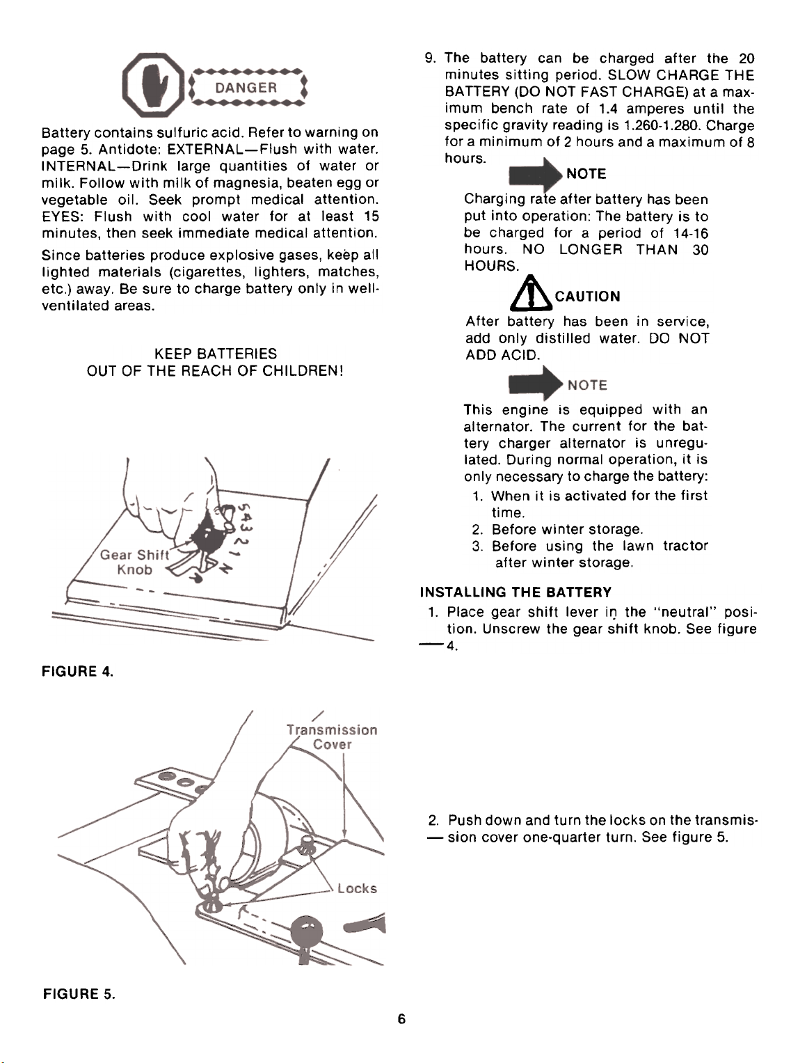
INSTAlliNG THE BATTERY
1. Place gear shift lever it) the "neutral" position. Unscrew the gear shift knob. See figure-4.
2. Push down and turn the locks on the transmis--sian
cover one-quarter turn. See figure 5.
6
Page 7
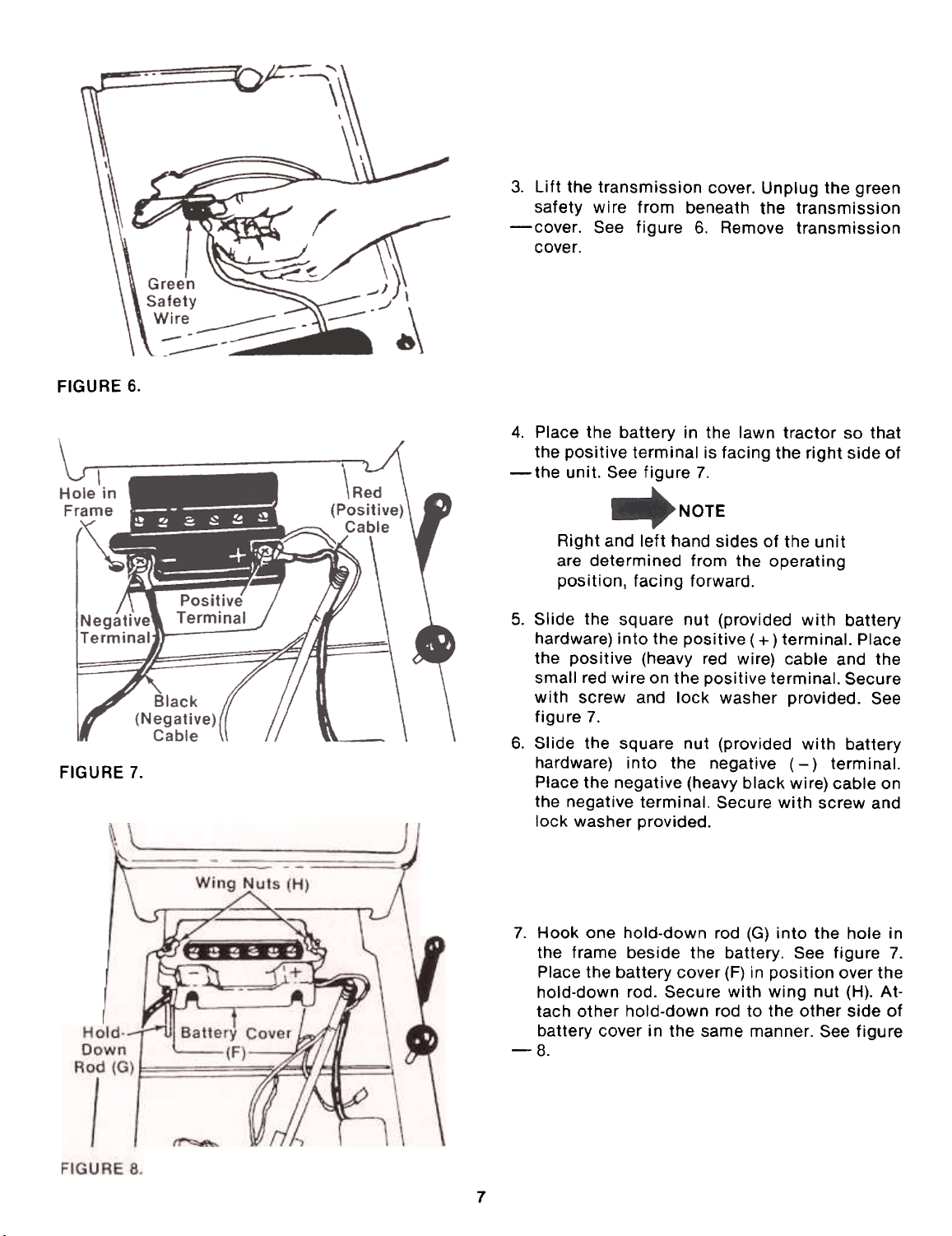
FIGURE 6.
FIGURE 7.
Lift the transmission cover. Unplug the green
safety wire from beneath the transmission-cover.
See figure 6. Remove transmission
cover.
4. Place the battery in the lawn tractor so that
the positive terminal is facing the right side of-the
unit. See figure 7.
NOTE
Right and left hand sides of the unit
are determined from the operating
position, facing forward.
Slide the square nut (provided with battery
hardware) into the positive (+) terminal. Place
the positive (heavy red wire) cable and the
small red wire on the positive terminal. Secure
with screw and lock washer provided. See
figure 7.6.
Slide the square nut (provided with battery
hardware) into the negative (-) terminal.
Place the negative (heavy black wire) cable on
the negative terminal. Secure with screw and
lock washer provided.
3.
5.
7. Hook one hold-down rod (G) into the hole in
the frame beside the battery. See figure 7.
Place the battery cover (F) in position over the
hold-down rod. Secure with wing nut (H). At-
tach other hold-down rod to the other side of
battery cover in the same manner. See figure-8.
7
Page 8
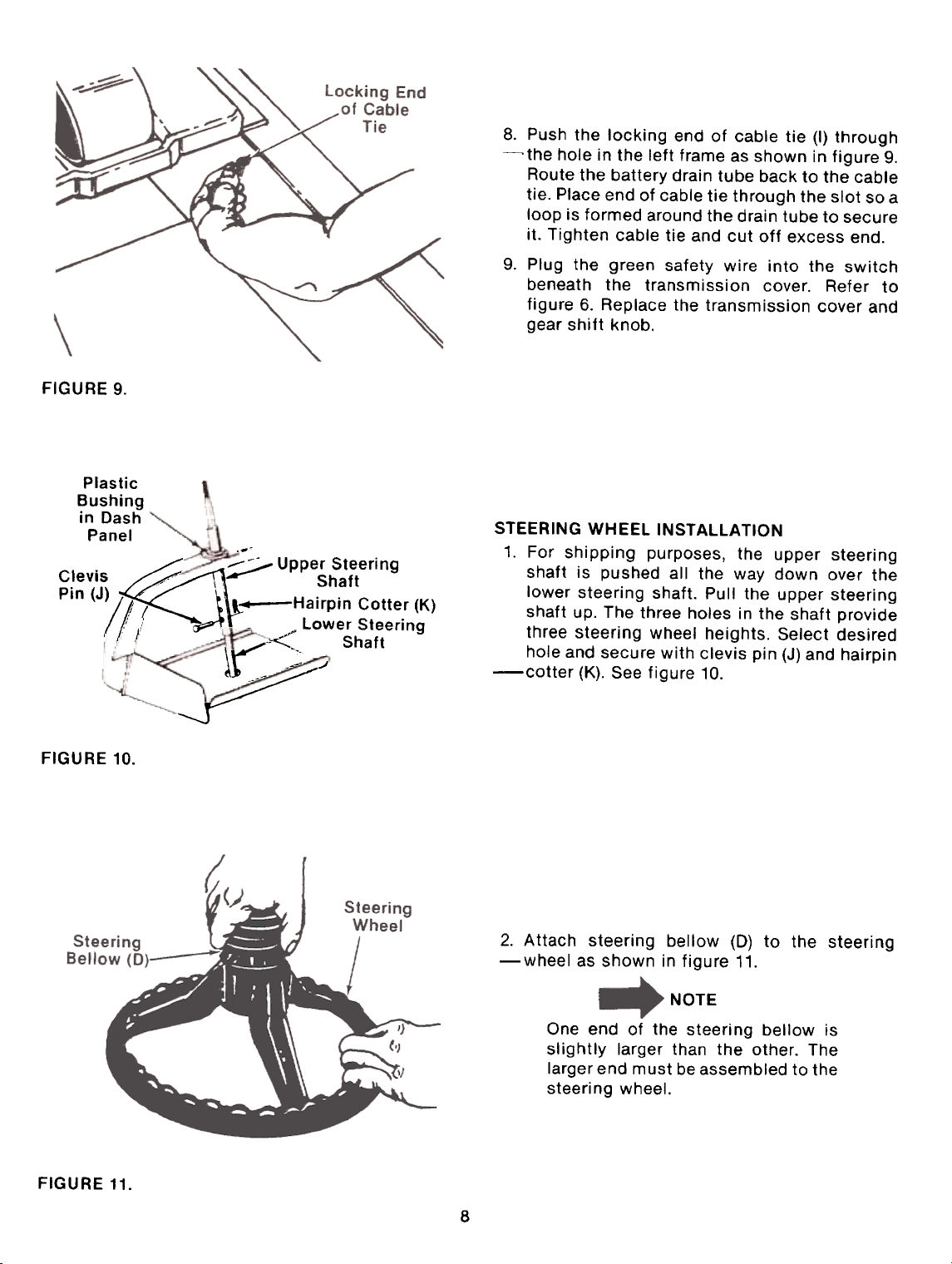
FIGURE 9.
Plastic
Bushing
in Dash
Panel
~! -Hairpin Cotte: (K)
._~
~ :;;;./ Upper Steering Clevis "' \ Shaft Pin (J)
,: I -Lower Steering
, I ;..~~ Shaft
.,..-
lr-::"~
Push the locking end of cable tie (I) through~the
hole in the left frame as shown in figure 9.
Route 1he battery drain tube back to the cable
tie. Place end of cable tie through the slot so a
loop is formed around the drain tube to secure
it. Tighten cable tie and cut off excess end.9.
Plug the green safety wire into the switch
beneath the transmission cover. Refer to
figure 6. Replace the transmission cover and
gear shift knob.
STEERING WHEEL INSTAllATION
1. For shipping purposes, the upper steering
shaft is pushed all the way down over the
lower steering shaft. Pull the upper steering
shaft up. The three holes in the shaft provide
three steering wheel heights. Select desired
hole and secure with clevis pin (J) and hairpin-cotter
(K). See figure 10.
FIGURE 10.
FIGURE 11.
~J--~
2. Attach steering bellow (D) to the steering-wheel
as shown in figure 11.
NOTE
One end of the steering bellow is
slightly larger than the other. The
larger end must be assembled to the
steering wheel.
8.
...t~
8
Page 9
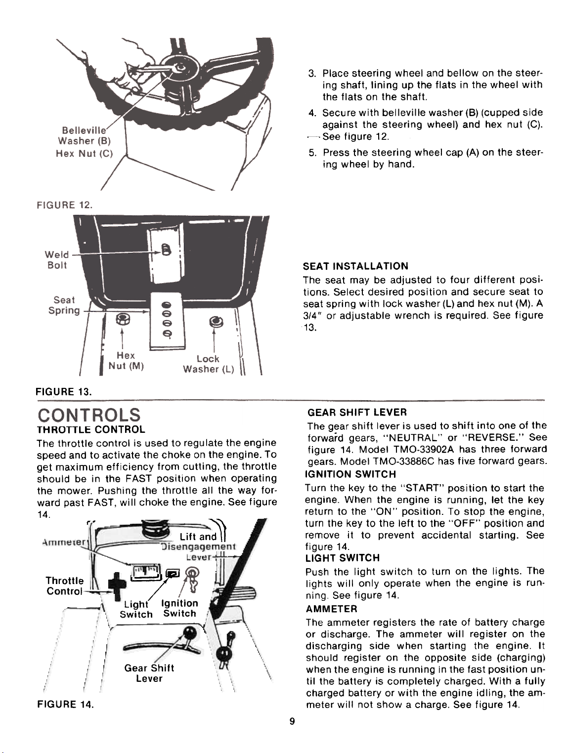
Place steering wheel and bellow on the steering shaft, lining up the flats in the wheel with
the flats on the shaft.4.
Secure with belleville washer (6) (cupped side
against the steering wheel) and hex nut (C).
~ See figure 12.
5. Press the steering wheel cap (A) on the steering wheel by hand.
SEAT INSTAllATION
The seat may be adjusted to four different posi.
tions. Select desired position and secure seat to
seat spring with lock washer (l) and hex nut (M). A
3/4" or adjustable wrench is required. See figure
13.
FIGURE 13.
THROTTLE CONTROL
The throttle control is used to regu late the eng ine
speed and to activate the choke on the engine. To
get maximum efficiency from cutting, the throttle
should be in the FAST position when operating
the mower. Pushing the throttle all the way forward past FAST, will choke the engine. See figure
14.
t'~
,-- ~
Lift an~
Throttle
Control~
FIGURE 14.
k..==!J/:,
Light Ignition
Switch Switch
Gear Shift
Lever
GEAR SHIFT LEVER
The gear shift lever is used to shift into one of the
forward gears, "NEUTRAL" or "REVERSE." See
figure 14. Model TMO-33902A has three forward
gears. Model TMO-33886C has fivE forward gears.
IGNITION SWITCH
Turn the key to the "START" position to start the
engine. When the engine is running, let the key
return to the "ON" position. To stop the engine,
turn the key to the left to the "OFF" position and
remove it to prevent accidental starting. See
figure 14.
LIGHT SWITCH
Push the light switch to turn on the lights. The
lights will only operate when the engine is run-
ning. See figure 14.
AMMETER
The ammeter registers the rate of battery charge
or discharge. The ammeter will register on the
discharging side when starting the engine. It
should register on the opposite side (charging)
when the engine is running in the fast position un-
til the battery is completely charged. With a fully
charged battery or with the engine idling, the am-
meter will not show a charge. See figure 14.
3.
9
Page 10
CLUTCH.BRAKE PEDALThe
clutch-brake pedal is located on the right side
of the lawn tractor. Depressing the clutch-brake
pedal part way disengages the clutch. Pressing
the pedal all the way down disengages the clutch
and engages the disc brake. See figure 15.
NOTE
The clutch-brake pedal must be
depressed to start the engine.
PARKING BRAKE
To set the parking brake, depress the clutch-brake
pedal and press the parking brake knob down. To
release the parking brake, depress and release the
clutch-brake pedal. See figure 15.
CUTTING CONTROLS
A. LIFT AND DISENGAGEMENT LEVER
The lift and disengagement lever is used to raise
and lower the cutting deck. Pulling it all the way
back and locking it disengages the blades. The lift
and disengagement lever must be in the disengaged position when starting the engine and
when shifting into reverse. See figure 14.
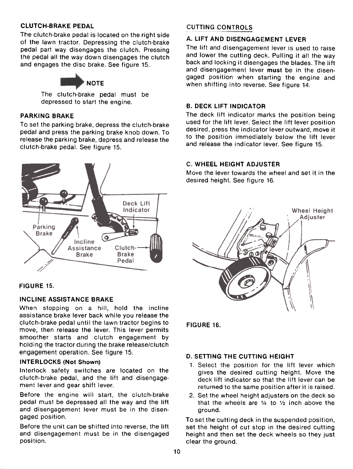
B. DECK LIFT INDICATOR
The deck lift indicator marks the position being
used for the lift lever. Select the lift lever positiondesired,
press the indicator lever outward, move it
to the position immediately below the lift lever
and release the indicator lever. See figure 15.
C. WHEEL HEIGHT ADJUSTER
Move the lever towards the wheel and set it in the
desired height. See figure 16.
FIGURE 15.
INCLINE ASSISTANCE BRAKE
When stopping on a hill, hold the incline
assistance brake lever back while you release the
clutch-brake pedal until the lawn tractor begins to
move, then release the lever. This lever permits
smoother starts and clutch engagement by
holding the tractor during the brake release/clutch
engagement operation. See figure 15.
INTERLOCKS (Not Shown)
Interlock safety switches are located on the
clutch-brake pedal, and the lift and disengagement lever and gear shift lever.
Before the engine will start, the clutch-brake
pedal must be depressed all the way and the lift
and disengagement lever must be in the disen-
gaged position.
Before the unit can be shifted into reverse, the lift
and disengagement must be in the disengaged
position.
FIGURE 16.
D. SETTING THE CUTTING HEIGHT
1. Select the position for the lift lever which
gives the desired cutting height. Move the
deck lift indicator so that the lift lever can be
returned to the same position after it is raised.
2. Set the wheel height adjusters on the deck so
that the wheels are 1/4 to 1/2 inch above the
ground.To
set the cutting deck in the suspended position,
set the height of cut stop in the desired cutting
height and then set the deck wheels so they just
clear the ground.
10
Page 11

OPERA TION
~ ~ CAUTION
~ 1. Keep all shields in place.
". 2. Before leaving operator's position:
~ a. Shift transmission to neutral
". b. Set parking brake
~ c. Disengage attachment clutch
". d. Shut off engine
~ e. Remove ignition key
". 3. Wait for all movement to stop before
~ servicing machine.
'" 4. Keep people and pets a safe distance
~ away from machine.
'" 5. Look to the rear before backing up.
TIRE PRESSURE
For shipping purposes, the tires on your unit may
be over.inflated. Tire pressure should be reduced
before unit is put into operation. Pressure should
be approximately 15 p.s.i. Equal tire pressure
should be maintained on all tires. Maximum tire
pressure is 30 p.s.i.
STARTING THE ENGINE
NOTE
To open the hood, simply lift
up on both sides of the hood.
Do not operate the lawn tractor if
the interlock system is malfunctioning because it is a safety device,
designed for protection.
Set the throttle control in the CHOKE posi-
tion. See figure 14.5.
Turn the ignition key to the "START" position.
When the engine is running, let the key return
to the "ON" position. See figure 14.6.
Move the throttle control to desired engine
speed.
STOPPING THE ENGINE
Turn the ignition key to the left to the "OFF" posi-
tion. Remove the key to prevent accidental start-
ing.
NOTE
A brief break-in period is essential
to ensure maximum engine and
mower life. The break-in consists of
running the engine at half speed for
a period of time required to use one
tank of gasoline. It is also recommended to change crankcase oil
after the first 5 hours of operation.
IMPORTANT
1. Service the engine with oil and gasoline as
described in the engine manual.
2. Depress the clutch-brake pedal and set the
parking brake. See figure 15.3.
Place the lift and disengagement lever in the
DISENGAGED position. See figure 15.
This unit is equipped with a safety
interlock system for your protec-
tion. The purpose of the safety inter-
lock system is to prevent the engine
from cranking or starting unless the
clutch-brake pedal is depressed
and the lift and disengagement
lever is in the disengaged position.
In addition, the lift and disen-
gagement lever must be in the disengaged position when the unit is
put into reverse or the engine will
shut off.
If you strike a foreign object, stop
the engine. Remove wire from sparkplug,
thoroughly inspect the unit
for any damage, and repair the damage before restarting and operating
the mower.
OPERATING THE MOWER
1. Set the desired cutting height.
2. Start the engine as instructed on page 11.
3. Move throttle control to desired engine speed.
4. Depress the clutch-brake pedal and shift into
first gear or reverse.
5. Release clutch-brake pedal slowly to put unit
into motion.
6. Depress the clutch-brake pedal when shifting
gears.
Do not force the gear shift lever!
11
4.
Page 12

The lawn tractor is brought to a stop by
depressing the clutch-brake pedal. The drive
belt will be disengaged and the brake will be
applied.
~ CAUTION
If the unit is not to be used for a
long period, place the gear shift
lever in NEUTRAL, stop the engine,
set the parking break and remove
the key. DO NOT leave the machine
on an incline.
OPERATING THE CUTTING BLADES
The cutting blades may be engaged while the lawn
tractor is moving or standing still. DO NOT engage
the cutting blades abruptly as the sudden belt tension on the pulley may cause the engine to stall.
NOTE
Under normal usage bag material is
subject to wear, and should be
checked periodically. Be sure any
replacement bag complies with the
mower manufacturer's recommen-daitons.
For replacement bags, use only fac-
tory authorized replacement bag
No. 764-0121.
SEAT ADJUSTMENT
The seat may be adjusted to one of four positions.
Remove hex nut and lock washer from under seatspring.After
When the blade drive is engaged,
keep feet and hands away from the
discharge opening, the blades or
any part of the deck.
Move the lift and disengagement lever into the
DISENGAGED position to raise the deck and
disengage the blades.
When the machine is used for other
than mowing operations, the blade
drive should be disengaged.
GRASS CATCHER Part No. 194-015-088 is
available as optional equipment for the lawn trac-
tor shown in this manual.
The mower should not be operated
without the entire grass catcher or
chute deflector in place.
desired seat location is selected, secure
seat to seat spring with lock washer and hex nut.
A 3/4" or adjustable wrench is required. See figure
17.
FIGURE 17.
STEERING WHEEL ADJUSTMENTThere
are three height positions for the steeringwheel.
To adjust the height of the steering wheel,
remove the hairpin cotter and clevis pin shown in
figure 18. Place the steering wheel in the positiondesired
and secure with hairpin cotter and clevispin.
7.
12
Page 13

r---~
J\
FIGURE 18.
WHEEL ADJUSTMENTThe
caster (forward slant of the king pin) and the
camber (tilt of the wheels out at the top) require no
adjustment. Automotive steering principles have
been used to determine the caster and camber on
the tractor. The front wheels should toe.in 1/8
inch.To
adjust the toe-in, follow these steps.
1. Remove the hex nut and lock washer, and
drop the tie rod end from the wheel bracket.
See figure 19.
2. Loosen the hex jam nut on tie rod.
3. Adjust the tie rod assembly for correct toe-in.
J
FIGURE 20. TOE-IN DIAGRAM
CARBURETOR ADJUSTMENT
Front of Tractor
-----
R
',
~ WARNING t
'
If any adjustments are made to the
engine while the engine is running(e.g.
carburetor), disengage allclutches,
and blades. Keep clear of
all moving parts. Be careful of
heated surfaces and muffler.
Minor carburetor adjustment may be required to
compensate for differences in fuel, temperature,
altitude and load. To adjust the carburetor, refer to
the separate engine manual packed with your unit.
BRAKE ADJUSTMENT
During normal operation of this machine, the
brake is subject to wear and will require periodic
examination and adjustment.
& CAUTION
Do not have the engine running
FIGURE 19.
Dimension "B" should be approximately 1/8" less
than Dimension "A." See figure 20.
A.) To increase Dimension "B," screw tie rod into
tie rod end.
B.) To decrease Dimension "B." unscrew tie rod
from tie rod end.
C.) Reassemble tie rod. Check dimensions. Read-
just if necessary.
L
To adjust the brake, proceed as follows.
13
when you adjust the brake.
1. Tighten the inside nut until the cam lever can
not be moved by hand.
2. Loosen the inside nut until the cam lever can
be pushed forward so that there is a 1/8" to
3/16" space between the cam lever and stop
bolt. See figure 21.
Page 14

FIGURE 21.
FIGURE 23.
Tighten the outside nut against the inside nut,
using two 1/2 II wrenches. See figure 22.
NOTE
Friction pads must be replaced when
the inside of cam lever touches the
housing.
FIGURE 22.
STEERING SHAFT
Lubricate steering shaft at least once a season
with light oil.
TRANSAXLE
The transaxle is lubricated and sealed at the factory and does not require checking. If disassembled for any reason, lubricate with 24 oz. of E.P.
Lithium grease.
FRONT WHEELS
The front wheels are provided with grease fittings.
Lubricate at least once a season with automotive
multi-purpose grease.
PIVOT POINTS
Lubricate all pivot points with light oil at least
once a season.
..:;;.
~WARN~N_G- .
Disconnect the spark plug wire
and ground against the engine before performing any repairs or main-
tenance.
STEERING GEARS
Lubricate teeth of steering gears with automotive
multi-purpose grease after every 25 hours of
operation or once a season. See figure 23.
3.
,'
CRANKCASE OIL
Check the oil level in the crankcase before each
use of the machine and after every five hours ofoperation.
Oil level should be maintained as in-
structed in the separate engine manual.
After the first five hours of operating a newengine,
drain the oil from the crankcase while
engine is still hot and refill crankcase with new
oil; thereafter change the oil every 25 hours ofoperation.
Refer to the engine manual.
14
Page 15

AIR CLEAN ER
Under normal operating conditions, the air
cleaner, located on top of the carburetor, must be
serviced after every ten hours of use. Under ex-
tremely dusty operating conditions, the air
cleaner must be serviced after every hour of
operation. To service the air cleaner, refer to the
separate engine manual packed with your unit.
CLEANING ENGINE AND BLADE HOUSING
Any fuel or oil spilled on the machine should be
wiped off promptly. Grass, leaves, and other dirt
must not be left to accumulate around the cooling
fins of the engine or on any part of the machine.
Clean the underside of the blade housing after
each mowing.
SPARK PLUG
The spark plug should be cleaned and the gap
reset once a season. Spark plug replacement is
recommended at the start of each mowing
season; check engine manual for correct plug
type and gap specification.
CUTTING BLADE
A. Removal for Sharpening or Replacement
t WARNING:
.~ Be sure to disconnect and ground
the spark plug wire and remove
ignition key before working on the
cutting blade to prevent accidentalengine
starting.
1. Remove the large bolt and lock washer which
holds the blade and adapter to the blade spin-
dle.2.
Remove the blade and adapter from the spin-
dle. Be careful not to lose the key on the spin-
dle.3.
If the blade or blade adapter needs replacing,
remove the two small bolts, lock washers and
nuts which hold the blade to the adapter.
B. Sharpening
Remove the cutting blade by following the direc-
tions of the preceding section.
When sharpening the blade, follow the original
angle of grind as a guide. It is extremely important
that each cutting edge receives an equal amount
of grinding to prevent an unbalanced blade. An unbalanced blade will cause excessive vibration
when rotating at high speeds, may cause damage
to the mower and could break, causing personal
injury.
blade can be tested for balance by balancing
it on a round shaft screwdriver. Remove metal
from the heavy side until it balances evenly.
NOTE
It is recommended that the blade
always be removed from the adapter
for the best test of balance.
Reassembly
Before reassembling the blade and the blade
adapter to the unit, lubricate the spindle and the
inner surface of the blade adapter with light oil.
Lubricating the bolt holes, bolts and inner surface
of the nuts with light oil is also recommended, A 4
oz. plastic bottle of light oil lubricant is available.
Order part number 737-0170. Engine oil may also
be used.
When replacing the blade, be sure to install the
blade with the side of the blade marked "Bottom"
(or with part number) facing the ground when the
mower is in the operating position. Make certain
key is in place on the crankshaft.
Blade Mounting Torque
3/8" Dia, Bolt 375 in. lb. min., 450 in, lb. max,
5/16" Dia. Bolt 150 in. lb. min., 250 in. lb. max.
To insure safe operation of your unit, ALL nuts
and bolts must be checked periodically for correct
tightness.
FUEL FILTER
Your unit is equipped with a replaceable in-line
fuel filter. Replace filter whenever contamination
or discoloration is noticed. Order replacement
filter through your engine authorized service
dealer,
BELT REMOVAL AN D REPLACEM ENT
Disconnect the spark plug wire and
ground it against the engine.
Figures 24 throlAgh 28 are shown
with the unit tipped up for clarity.
It is not necessary to tip the unit
to remove the belts.
Removing the Deck Belt
1. Place the lift lever in the disengaged position.
2. Remove the two hex bolts (belt keepers) from
the engine pulley belt guard. See figure 24.
The
C.
15
Page 16

FIGURE 24.
3. Unhook the deck belt from the engine. pulley.
4. Place the lift lever in the engaged (all the way
forward) position.
5. Disconnect the six deck links by removing the
hairpin cotters and flat washers.
6. Slide the deck from beneath the lawn tractor.
7. Remove the belt guards at each deck pulley by
removing the hex bolts, lock washers and hex
nuts. See figure 25.
8. Remove and replace the belt, following the in-
structions in reverse order.
u
..."
Pulleys ,.f
,f"
~ .
~ .
Bolts
Lock Washers
Hex Nuts,
~
;)7
FIGURE 25.
Removing the Drive Belt
1. Follow steps 1 through 3 on removing the
deck belt.
2. Remove the two bolts, lock washers and nuts
on each side of the frame which hold the
engine pulley belt guard to the frame. See
figure 26.
,;/
f.
FIGURE 26.
Remove the engine pulley belt guard by slip.
ping it back and to the right. See figure 27.
FIGURE 27.
Remove the bolt, lock washer and nut which
hold the idler pulley to the idler bracket. See
figure 28.
NOTE
Upon reassembly, the hub side of
the idler pulley must be assembled
against the idler bracket.
3.
11M""",,
4.
16
Page 17

G.ound 10 F,.m.
1
I
~
,j II Vr
~
16 ,
\
/
_3
6,
---4
"I -' T~~ I I f
~
;. 0'
j ,Ic
r~1
~uu..d
I
14 I (
PARTS LIST FOR ELECTRICAL SYSTEM MODEL TMO.33902A
REF. PART DESCRIPTION REF. PART DESCRIP
1 725.0459 Circuit Breaker 9 725-0916 Ground Wire
2 725-0759 Spring Switch (Reverse 10 725-0222 Head Light
Safety) 11 725.0976 Ground Wire 7.25" Lg.
3 725-0975 Ground Wire 9.0" Lg. (Black (Black)
Neg.) 12 725-1042 Wire Harness
4 725-0514 12 Volt Battery 13 725-0925 Ammeter
5 725-0577 Safety Switch (Clutch) 14 725-0803 Safety Switch (P.T.a.)
6 725-0201 Ignition Key 15 725-0771 Solenoid
7 725-0267 Ignition Switch 16 725-0150 Electric Wire (Red Pas.)
8 725-0634 Light Switch
~-\ -:--~~
8
~~ 81ue
7 81ac
~ "."'4
~_.
I r
!;Ic'\,2;,,-:C,," ,..
12 I
Tecum.e" Eng;ne~'-:--"'",,[==J
===::~~-~ "'O". _
&\
SI.'le, 11 /1
Yellow (JI G,o"nO
Black /
B'ue
F,.me
10,
I.
10
TIONNO. NO. NO. NO.
G'~un.
r-E
I/~
9
2 GrounC 10
/ (0)
,~
£ 15
Rd ~
~ ~
~ .
n~l: ~r~
.Bloc.
~-G L ~ed ---
-~ ,
16 --ROd---:-? ~
0.
a;
""0
~~-~-'-'"~--~ I~ .
~?~~
9
!~ ;,,0".. -..,
10
"c 1
~~: ~ All
j&S Eng,ne
/ ~~; ~;l
,~=::~ ~
/ G..un~
11 to
St.,t.,
'W1 ~~2
G'oun.~
~,
/~
F..me
2
~,.a--<5
~13
~
~I~~
~
~~~~
~~~~
-~".
.
---
Page 18

Page 19

TM Q.33902A
T M Q.33886C 10 H.P. 38// LAWN TRACTORS
PARTS LIST FOR MODELS TMO.33902A AND TMO-33886C
\NO.
732-0414
14665 -615
3 '
712-0272
4
736-0463
5
723-0302
6
710-0473
7
723-0155
751-0172
8
9
726-0153
751-0173
726-0207
09960
712-0287
736-0329
725-0222
710-0118
723-0360
14781 -615
712-0113
14606
13863
14619
13862
710-0726
710-0524
PART
NO.
REF,
T!
10
11
12
13
14
15
16
17
18
19
22
23
24
25
26
27
28 710-0134
DESCRIPTION
Hood Spri ng
Hood
Hex Sems Nut #10-24 Thd.*
FI-Wash. .281" 1.0. x .62"
0.0. x .051
Hood Stop 7" Lg.
Truss Hd. Scr. #10-24 x 112"
Lg.*
Fuel Cap Gauge
Fuel Tank
Tie Strap
Fuel Line
Hose Clamp
Headlight Retainer
Hex Nut '/4-20 Thd.*
L-Wash. '/4" 1.0.*
Headlight
Hex Bolt 5/16-18 x .75" Lg.*
Foot Pad
Grille Ass'y.
Wing Nut '/4-20 Plastic
Lower Frame
Grille Mount Brkt.-L.H.
Front Pivot Brkt.
Grille Mount Brkt.-R.H.
Hex Wash. Hd. AB- Tap Scr.
5/16 x .75" Lg.
Truss Hd. Scr. '/4-20 x 1.75"
Lg.*
Carriage Bolt '/4 -20 x .62"
REF.I
~I
48
50
51
52
54
57
59
61
63
64 710-0258
67
69
70
71
72
73
75
79
80
81
82
PART
NO.
726-0222
14607
712-0267
736-0119
757-0264
710-0726
731-0561
726-0151
710-0227
749-0517
710-0255
14748
14749
15933
831-0692
746-0500
746-0504
725-0267
725-0201
712-0206
736-0921
710-0376
Lg.*
29
30
33
36
37
38
39
42
43
44
45
46
47
14604 -615
761-0169
710-0323
14671
14655
710-0118
14602
731-0708
711-0222
725-0514
14603
15823
725-0759
Running Board (R.H. & L.H.:
Blade Brake Ass'y.
Truss Mach. Scr. 5/16-18 x
.75" Lg.*
Fender Clamp
Fender (R.H. & L.H.)
Hex Bolt 5/16-18 x .75" Lg.*
R.H. Side Frame
Battery Cover
Battery Hold Down Rod
12-Y Battery
L.H. Side Frame
Transmission Panel
Reverse Safety Switch
732-0354
83
725-0634
84
725-0925
86
731-0511
88
738-0526
89
712-0287
90
91
710-0621
93
735-0144
712-032494
9596757-0272
736-0463
DESCRIPTION
Insulator Nut Plate
Hitch Plate
Hex Nut 5/16-18 Thd.*
L-Wash. 5/16" 1.0.*
Seat Ass'y.
Hex Wash. Hd. AB- Tap Scr.
5/16 x .62" Lg.
Tool Tray
Fastener
Truss Hd. Scr. #8 x .50"
Lg.
Hex Bolt 1/4-20 x .62"
Lg.*
Grille Support Rod (R.H. &
L.H.)
Truss Hd. Scr. 1/4-20 x .75"
Lg.*
R.H.-Grille Side Panel
L.H.-Grille Side Panel
Dash Panel Ass'y.
Throttle Control Box Ass'y.
Throttle Control Wire
(TMO-33902A)
Throttle Control Wire
(TM 0-33886C)
Ignition Switch
~gnition Key
Hex Nut V2-13 Thd.*
L-Wash. V2" 1.0.*
Hex Bolt 5/16-18 x 1.00"
Lg.*
Seat Spring
Light Switch
Ammeter
Molding Strip 27" Lg.
Running Board Rod
Hex Nut 1/4-20 Thd.*
Hex Bolt 5/16-18 x .75" Lg.*
Rubber Wash. V2" 1.0. x
1.0" 0.0.
Hex Sems Ins. L-Nut 1/4-20
Thd.
Trim Strip
FI-Wash. .296 1.0. x .62" 0.0.
*Common Hardware-May be purchased locally.
Important: Do not order by reference number
(Ref. No.).
NOTE: Specifications subject to change without
notice or obligation.
23
Page 20

Page 21

Page 22

Page 23

Page 24

Page 25

Page 26

Page 27

Page 28

Page 29

Page 30

Page 31

Page 32

HOW TO 08T AIN
REPLACEMENT PARTS AND SERVICE
The merchandise you have purchased from us has been
carefully engineered and manufactured under Wards rigid
quality standards and should give you satisfactory and
dependable operation. However, like all mechanical merchan-
dise, it may occasionally require adjustment, replacement
parts or maintenance. Should you ever need technical
assistance or parts, please contact or write your nearest Wards
Retail Store, Central Service Center, Catalog Store or Catalog
House.
Provide the following:
1. Model, serial number and all of the other data shown on the
model plate
2. The date and the Wards branch from which you purchased
your merchandise.
3. State briefly the trouble you are having.
4. Also give the part number or numbers as shown in the parts
list that came with the product.
Replacement Parts will be made available at current prices. If
requested, prices will be quoted in advance when not listed.
If you order parts by mail, you will pay the transportation
charges from the shipping point.
PART NO. 770-3439
UNIT MODEL NO.
UNIT SERIAL NO.
ENGINE MODEL NO.
TYPE NO.
CODE NO.
PRINTED IN U.S.A.
134-696-088
134-697-088
 Loading...