

Page 1
Instruction Manual
Item No.: 724723
120V~, 60Hz, 15W
Wards.com 1•888•557•3848
Montgomery Ward Customer Service
1112 7Th Avenue, Monroe, WI 53566
8:00 am to Midnight, Monday through Friday
Wards.com 1•888•557•3848
Sewing Machine
Free Arm
Sewing!
MODEL: JW12
Page 2

Thank you for purchasing your Sewing Machine by Montgomery Ward®.
It will perform to the highest standard, time after time, with all the
convenience and durability you rely on from Wards.
We guarantee it!
Perfect for basic or advanced sewing, this machine is a real workhorse. The
54 stitching features lets you make buttonholes to zippers and everything in
between. You’ll love the light weight portability and well lit LED work surface.
3
PLEASE READ THESE INSTRUCTIONS BEFORE USE
Basic safety precautions should always be followed when using your sewing machine,
especially when children are present.
WARNING: TO AVOID THE RISK OF ELECTRICAL SHOCK, ALWAYS MAKE
SURE THE PRODUCT IS UNPLUGGED FROM THE ELECTRICAL OUTLET
BEFORE ASSEMBLING, DISASSEMBLING OR RELOCATING. DO NOT TRY TO
SERVICE THIS PRODUCT YOURSELF.
1. Do not allow to be used as a toy. Supervision is necessary when used by or
near children.
2. To protect against electrical shock, do not place cord, plug or appliance in water
or other liquid.
3. Unplug from outlet when not in use and before cleaning.
4. Do not operate any appliance with a damaged cord or plug, or after the appliance malfunctions or has been damaged in any manner. Call our toll-free
customer service number for information regarding replacement, or returning
the product.
5. The use of accessory attachments not recommended by the manufacturer may
cause personal injury or damage to the appliance.
6. Do not use outdoors.
7. Never drop or insert any object into any opening. Never operate the appliance
with any air opening blocked. Keep ventilation openings of this sewing machine
and foot controller free from accumulation of lint, dust and loose cloth.
8. Do not operate where aerosol (spray) products are being used or where oxygen
is being administered.
9. Do not use appliance for other than intended use.
10. To disconnect, turn all controls to the off (“O”) position, then remove plug from
outlet. Do NOT pull out by cord.
11. Keep fingers away from all moving parts. Special care is required around the
sewing machine needle.
12. Always use the proper needle plate. The wrong plate can cause the needle to
break.
13. Do not use bent needles.
14. Do not pull or push fabric while stitching. It may deflect the needle causing it to
break.
Important Safeguards ........................3-4
Polarized Plug ......................................4
Parts & Features ................................5-6
Operating Instructions .....................6-15
How to Use ....................................16-26
Cleaning & Care ............................27-28
Thread & Needle Guide ...................... 29
Troubleshooting .................................. 30
Warranty & Return Information ......32-33
Table of Contents
2
1•888•557•3848
Wards.com
Important Safeguards
PLEASE SAVE THESE INSTRUCTIONS
THIS APPLIANCE IS FOR HOUSEHOLD USE ONLY
© 2015 Montgomery Ward, Inc. All rights reserved.
ank you
for your
purchase!
3102543
Conforms to UL Std. 471
Certified to CSA Std. C22.2 No. 120-13
Page 3
4
1•888•557•3848
Wards.com
5
Parts & Features
Polarized Plug
This appliance has a polarized plug (one blade is wider than the other). As a safety
feature to reduce the risk of electrical shock, this plug is intended to fit a polarized
outlet only one way. If the plug does not fit fully in the outlet, reverse the plug. If it
still does not fit, contact a qualified electrician. Do not attempt to modify the plug in
any way.
SHORT CORD INSTRUCTIONS
1. A short power supply cord is provided to reduce the risk resulting from
becoming entangled in or tripping over a longer cord.
2. Longer detachable power-supply cords or extension cords are available and may
be used if care is exercised in their use.
3. If a long detachable power cord or extension cord is used:
• The marked electrical rating of the detachable power supply cord or extension
cord should be at least as great as the electrical rating of the appliance.
• If the appliance is of the grounded type, the extension cord should be the same
type 3-wire.
• The longer cord should be arranged so that it will not drape over the countertop
or tabletop where it can be pulled on by children or tripped over.
Important Safeguards (cont’d)
15. Switch this sewing machine off (“O”) when making any adjustment in the needle
area, such as threading the needle, changing the needle, threading the bobbin
or changing the presser foot, and the like.
16. Always unplug this sewing machine from the electrical outlet when removing
covers, lubricating, or when making any other adjustments mentioned in this
manual.
17. Do not store the machine in a high-humidity area, near a heat radiator, or in
direct sunlight.
18. Dispose of this appliance in accordance with local regulations.
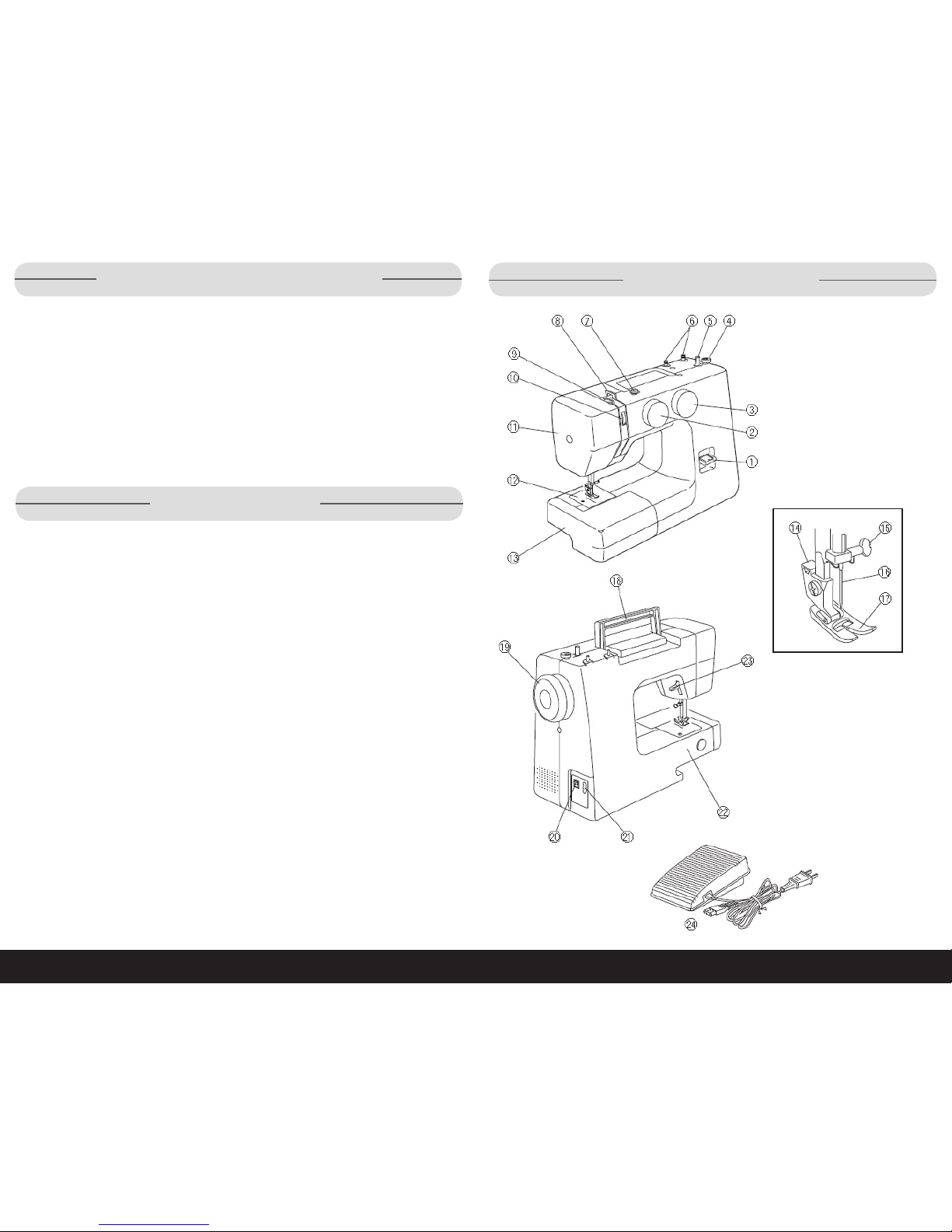
1. Reverse stitch button
2. Pattern selector dial
3. Stitch length dial
4. Bobbin winder stopper
5. Bobbin winder spindle
6. Spool pins
7. Bobbin winder thread guide
8. Thread guide
9. Thread take-up lever
10. Thread tension dial
11. Face cover
12. Needle plate
13. Extension table
14. Presser foot holder
15. Needle clamp
16. Needle
17. Presser foot
18. Carrying handle
19. Handwheel
20. Power switch
21. Machine socket
22. Free arm
23. Presser foot lifter
24. Foot control
Page 4
7
6
1•888•557•3848
Wards.com
Operating Instructions
Parts & Features (cont’d)
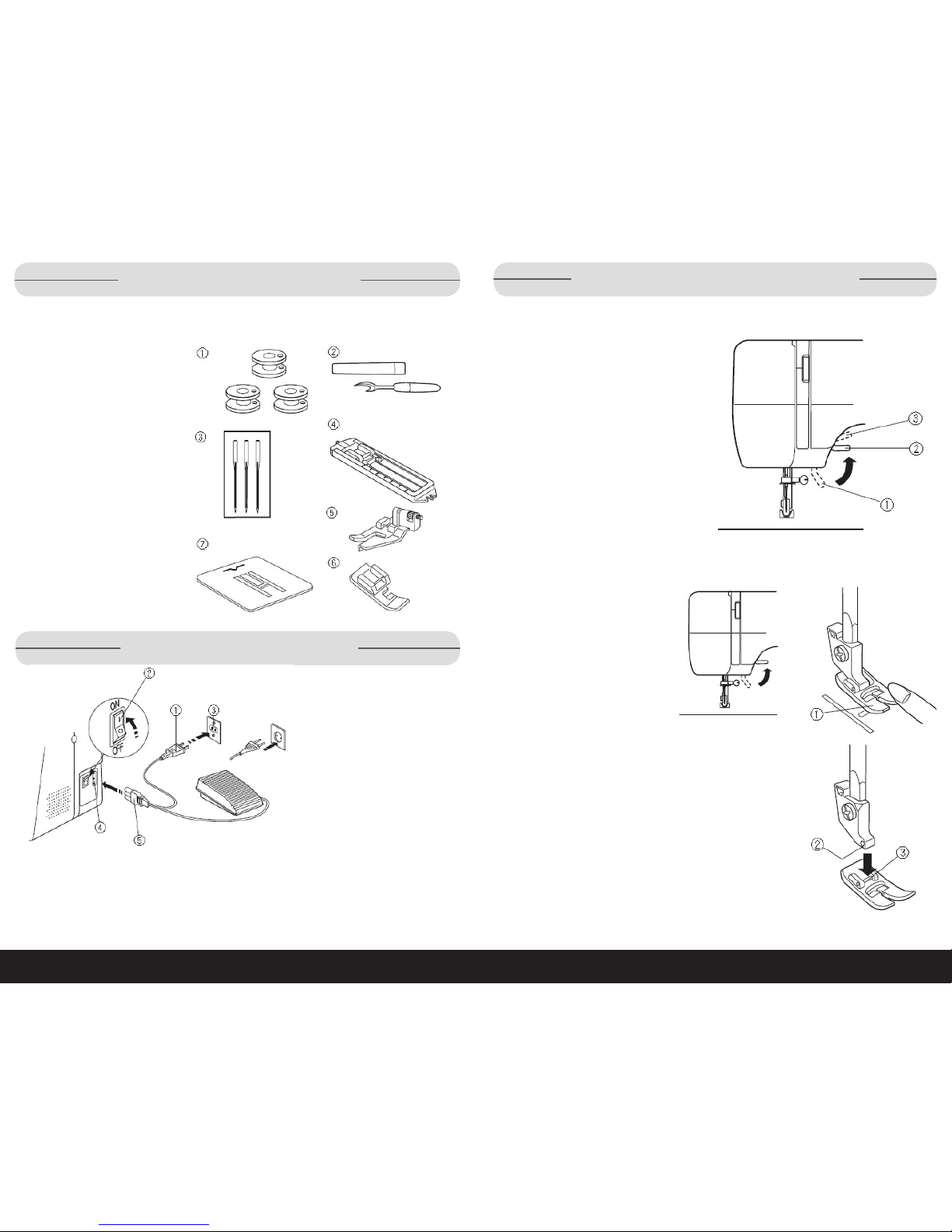
Accessories
Sewing accessories are conveniently located in the extension table.
1. Bobbins
2. Seam ripper/ Buttonhole
opener
3. Needle set
4. Sliding buttonhole foot
5. Blind hem foot
6. Zipper foot
7. Darning plate
1. Turn the power switch (2)
to OFF.
2. Insert the machine plug
(5) into the machine
socket (4).
3. Insert the power supply
plug (1) into the outlet (3).
4. Turn the power switch (2)
to ON.
While in operation, always keep your eyes on the sewing area, and do not touch
any moving parts such as the thread take-up lever, handwheel or needle. Always
turn off the power switch and unplug from the power supply when leaving the machine unattended, attaching or removing parts.
Do not place anything on the foot control causing the machine to run inadvertently.
Operating Instructions (cont’d)
Presser Foot Lifter
The presser foot lifter raises and lowers
the presser foot. It can be raised 1/4"
higher than the normal up position for
easy removal of the presser foot or for
ease of placement of heavier material.
Presser Foot Positions
1. Lowest
2. Normal
3. Highest
Changing Presser Foot
CAUTION: When removing or
attaching presser foot, turn
the power switch to OFF.
Remove:
1. Turn the handwheel toward
you to raise the needle bar to
its highest position.
2. Raise the presser foot.
3. Push down on the toe of the
presser foot (1) to snap it off
the foot holder.
Attach:
1. Place the presser foot so that
the pin (3) on the foot lines up
directly below the groove (2) of
the foot holder.
2. Lower the foot holder to lock
the foot in place.
Page 5
7
8
9
1•888•557•3848
Wards.com
Operating Instructions (cont’d) Operating Instructions (cont’d)
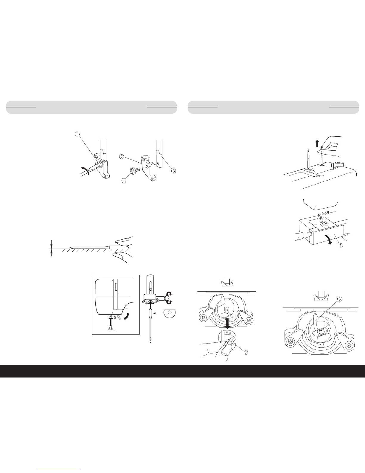
Foot Holder
Remove:
Remove the thumb screw (1) by
turning it counterclockwise with
a screwdriver.
Attach:
1. Match the hole in the foot
holder (2) with the threaded
hole in the presser bar (3).
2. Fit the thumb screw (1) into
the hole.
3. Tighten the screw by turning it clockwise with screwdriver.
Needles
Before changing needles, confirm that they are not bent or warped. Place the
flat side of the needle on something flat (needle plate, glass etc.). The clearance
between the needle and flat surface should be consistent. Never use a bent or
blunt needle.
Changing:
1. Raise the needle by turning the
handwheel toward you.
2. Lower the presser foot.
3. Loosen the needle clamp screw
by turning it counterclockwise.
4. Remove the needle from the
clamp.
5. Insert the new needle into the
clamp with the flat side away from
you.
6. Push it up as far as it will go and
tighten the clamp screw firmly with
the screwdriver.
Spool Pins
The spool pins are used for holding the spool of thread in order to feed it to the machine. To use, pull the spool pin up. Push down to store.
Bobbin Case
Inserting or removing:
Open hook cover (1).
Raise the needle by turning the handwheel toward you. Take out the bobbin case by
holding the latch (2). Insert the bobbin case by placing the horn (3) into the recess
of the hook race.
Page 6
10 11
1•888•557•3848
Wards.com
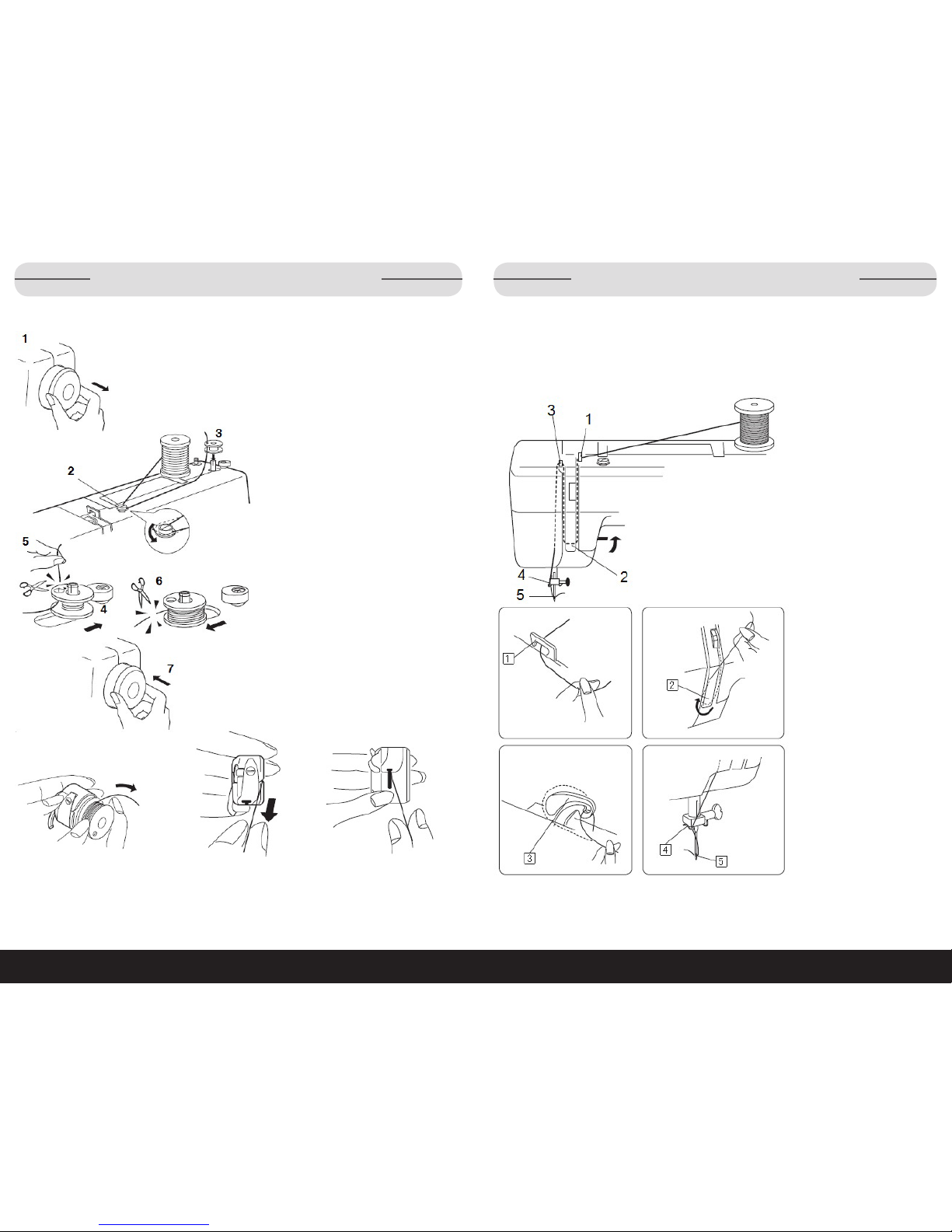
Operating Instructions (cont’d)
Bobbin Winding
1. Pull the handwheel (1) out.
2. Draw the thread from the spool
and guide the thread around the
bobbin winder thread guide (2).
3. Insert the thread through the hole
in the bobbin (3) from the inside to
the outside. Put the bobbin on the
bobbin winder spindle.
4. Push it to the right.
5. With the free end of the thread
held in your hand, depress the
foot control. Stop the machine
when it has made a few turns and
cut the thread (5) close to the hole
in the bobbin.
6. Depress the foot control again.
When the bobbin (6) is fully
wound, stop the machine. Return
the bobbin winder spindle to its
original position by moving the
spindle to the left, and cut the
thread.
7. Push the handwheel (7) back into
the original position.
Note: Return the bobbin winder
spindle when the machine stops.
Operating Instructions (cont’d)
Bobbin Case Threading
Place the bobbin into the
bobbin case. Make sure
the thread unwinds in the
direction of arrow.
Pull the thread into
the bobbin case
slot.
Draw the thread under
the tension spring and
into the delivery eye,
leaving about 4" of
free thread.
Threading the Machine
First, raise the take-up lever to its highest position by turning the handwheel toward
you. Next, raise the presser foot. Then place a spool on the spool pin as shown,
with thread coming from back of the spool.
1. Draw the thread into
thread guide (1) using
both hands.
2. While holding the
thread near spool,
draw thread down into
the tension area and
then around the check
spring holder (2).
3. Firmly draw the thread
up and through the
take-up lever (3) from
right to left.
4. Then draw the thread
down and slip it into
needle bar thread
guide (4) on the left.
5. Thread the needle eye
(5) from front to back.
Page 7

1312
Wards.com
1•888•557•3848
Operating Instructions (cont’d)
Drawing Up Bobbin Thread
Raise the presser foot and hold
the needle thread lightly with
your left hand.
Turn the handwheel slowly
toward you with your right hand
until the needle goes down and
continue turning the handwheel
until the take-up lever is at its
highest position. Lightly draw
up the needle thread forming a
loop of the bobbin thread.
Pull 6" of both threads back and under the presser foot.
Operating Instructions (cont’d)
Thread Tension Dial
Correct tension:
The thread tension is adjusted
depending on the sewing materials,
layers of fabric and sewing method.
For an ideal zigzag stitch, the bobbin thread does not show on the right
side (top side) of the fabric, and the
needle thread shows slightly on the
wrong side (bottom side) of the fabric.
(1) Needle thread (Top thread)
(2) Bobbin thread (Bottom thread)
(3) Right side (Top side) of fabric
(4) Wrong side (Bottom side) of fabric
(5) Thread tension dial
(6) Setting mark
Tension too tight:
When the bobbin thread (2) (bottom
thread) appears on the right side (3)
(top side) of the fabric, loosen the
needle thread tension by moving the
dial (5) to a lower number.
Tension too loose:
When the needle thread (1) (top
thread) appears on the wrong side (4)
(bottom side) of the fabric, tighten the
needle thread tension by moving the
dial (5) to a higher number.
Page 8

14
15
1•888•557•3848
Wards.com
Operating Instructions (cont’d)
Stitch Selector Dial
Turn the stitch selector dial to set the setting
mark (1) with the symbol corresponding to the
desired pattern.
CAUTION: To avoid needle or fabric damage,
make sure the needle is up and out of the fabric
while selecting a stitch.
Stitch Length Dial
• Turn the stitch length dial to set the
setting mark (1) with the desired stitch
length. The higher the number, the
longer the stitch length.
• Adjust the dial in the 0.5-4 range
when you sew the zigzag stitch.
• Set the dial at “S.S.” to sew the
stretch stitch pattern sewing.
• If the stretch stitch pattern is uneven,
turn the stitch length dial in the direction of “–” to compress it, or “+” to
expand it.
Operating Instructions (cont’d)
Reverse Stitch Button
To sew in reverse, keep the reverse stitch button depressed.
Darning Plate
Position the darning plate with 3 pins on the bottom.
Fit the darning plate pins into the needle plate holes.
The feed dogs will show through the darning plate holes.
Extension Table
The extension table provides added sewing surface and can be easily
removed for free arm sewing by pulling the table away from the machine.
Free Arm Sewing
Avoid fabric bunching around the needle when
bartacking to reinforce pockets, plackets and
waistlines. For stitching sleeves, waistbands,
pant legs or any circular garment area. For
darning socks or mending knees, elbows or
areas of wear in children’s clothes.
Page 9

16 17
1•888•557•3848
Wards.com
How to Use
Basic Sewing
Straight Stitch
(1) Pattern selector: A or B
(2) Presser foot: Zigzag foot
(3) Thread tension: 2–6
(4) Stitch length: 1.5–4
1. Raise the presser foot and position
the fabric with its edge lining up with
a seam guide line on the needle
plate.
2. Lower the needle into the fabric.
3. Lower the presser foot and smooth
the threads toward the back.
4. Depress the foot control.
5. Gently guide the fabric along the
guide line letting the fabric feed by
itself.
• For fastening the end of seams,
press the reverse stitch lever and
sew several reverse stitches.
6. Raise the presser foot and remove
the fabric, drawing the threads to the
back.
7. Cut the threads with the thread cutter (1).
• The threads are now the right
length to begin sewing the next
seam.
How to Use (cont’d)
Changing Direction
1. Stop the machine and turn
the handwheel toward you to
bring the needle down into the
fabric.
2. Raise the presser foot.
3. Pivot the fabric around the
needle to change sewing
direction as desired.
4. Lower the presser foot and
continue sewing.
Seam Guidelines
The numbers on the needle plate indicate the distance between the center needle
position and the guideline.
The numbers in front are centimeters and on back are fractions of an inch.
Number 15 20 4/8 5/8 6/8
Distance (in.) 19/32 25/32 33/64 5/8 3/4
(1) Center needle position
(2) Guidelines
(3) Numbers
Page 10

1312
Wards.com
1•888•557•3848
18 19
1•888•557•3848
Wards.com
How to Use (cont’d)
Turning a Square Corner
To turn a square corner 5/8” (1.6 cm) from the fabric edge.
1. Stop stitching and lower the needle by turning the handwheel counterclockwise.
2. Raise the presser foot and turn the fabric to line the edge with the 5/8” (1.6 cm)
seam guide.
3. Lower the presser foot and begin stitching in the new direction.
4. Line up the fabric edge facing you with the cornering guide (1) shown.
Zigzag Stitch
Simple zigzag stitching is widely used for
overcasting, sewing on buttons, etc.
(1) Pattern selector: C
(2) Presser foot: Zigzag foot
(3) Thread tension: 2–5
(4) Stitch length: 0.5–4
Turn the pattern selector between
the zigzag stitch (C) and straight
stitch (left position) (B) to adjust
the stitch width.
How to Use (cont’d)
Utility Stitching
Tricot Stitch
This stitch is used to finish the
raw edge on synthetics and other
fabrics that tend to pucker.
(1) Pattern selector: D
(2) Presser foot: Zigzag foot
(3) Thread tension: 1–4
(4) Stitch length: 0.5–4
Place your fabric to allow a 1.6 cm (5/8”) seam.
Trim the seam allowance after sewing.
Be careful not to cut the stitches.
Knit Stitch
This knit stitch is ideal for sewing
swimwear and stretch velour
because it provides the greatest
amount of elasticity and strength.
(1) Pattern selector: G
(2) Presser foot: Zigzag foot
(3) Thread tension: 1–4
(4) Stitch length: S.S.
Place your fabric to allow a 1.6 cm (5/8˝) seam.
Trim the seam allowance after sewing.
Be careful not to cut the stitches.
Page 11

20 21
1•888•557•3848
Wards.com
How to Use (cont’d) How to Use (cont’d)
Straight Stitch
(1) Pattern selector: A
(2) Presser foot: Zigzag foot
(3) Thread tension: 2–6
(4) Stitch length: S.S.
This strong, durable stitch is recommended
where both elasticity and strength are necessary to ensure comfort and durability.
Use it to reinforce areas such as crotch
and armhole seams as well as to eliminate
puckering on knits and stretch fabrics. Also
use when constructing items requiring
extra strength such as backpacks.
Rick-Rack Stitch
(1) Pattern selector: C
(2) Presser foot: Zigzag foot
(3) Thread tension: 2–6
(4) Stitch length: S.S.
Sew on stretch fabrics in any area that you might
use a zigzag stitch. This stitch is also used as a
decorative topstitch.
Decorative Stitching
Shell Tuck
(1) Pattern selector: G
(2) Presser foot: Zigzag foot
(3) Thread tension: 6–8
(4) Stitch length: 2–3
1. Use a lightweight fabric (tricot, for example).
2. Fold and stitch on the bias.
3. When the needle swings to the right, allow
the needle to just clear the folded edge of
the fabric.
4. After stitching, open the fabric and iron press
the tucks flat to one side.
Note: Increase the needle thread tension to form
prominent tucks.
Smocking
(1) Pattern selector: D
(2) Presser foot: Zigzag foot
(3) Thread tension: 1–4
(4) Stitch length: S.S.
1. With the stitch length at “4,” sew straight
stitching lines (1) 1 cm (3/8") apart,
across the area to be smocked.
2. Knot the threads along one edge.
3. Pull the bobbin threads and distribute
the gathers evenly.
4. Secure the threads at the other end.
5. Sew the decorative stitch between the
gathering stitches.
6. Pull out the gathering stitches.
Page 12

22 23
1•888•557•3848
Wards.com
How to Use (cont’d)
How to Use (cont’d)
Sewing Buttons
(1) Pattern selector: C
(2) Presser foot: Zigzag foot
(3) Thread tension: 3–7
(4) Stitch length: Any
(5) Darning plate
1. Attach the darning plate.
2. Match the holes in the button with the horizontal slot on the presser foot.
3. Adjust the stitch width matching the distance of the holes in the button.
4. Lower the foot to hold the button in place.
5. Check to see if the needle enters into the holes in the button by manually turning
the handwheel.
6. Sew about ten (10) stitches.
To strengthen the shank:
1. Cut the threads leaving about 4.0" (10.0 cm).
2. Bring the needle thread down through one of the holes in the button and wind it
around the shank.
3. Bring the needle thread to the wrong side (bottom side) and knot.
4. After button sewing is completed, remove the darning plate.
Appliqué
(1) Pattern selector: C
(2) Presser foot: Zigzag foot
(3) Thread tension: 1–4
(4) Stitch length: 0.5–1
1. Baste (or fuse with iron-on fabric joiner) appliqué
pieces on the fabric.
2. Stitch around the appliqué making sure the needle
falls along the outer edge of the appliqué.
3. When sewing corners, lower the needle down into
the fabric.
4. Raise the presser foot and pivot the fabric to the
right or left.
Stretch Stitch Patterns
(1) Pattern selector: A-G
(2) Presser foot: Zigzag foot
(3) Thread tension: 1–4
(4) Stitch length: S.S.
If forward and reverse feeds become unbalanced
due to the type of fabric, adjust the balance by
turning the stitch length dial as follows:
If patterns are compressed, turn dial toward “+”.
If patterns are drawn, turn the dial toward “–”.
Page 13

2524
Wards.com
1•888•557•3848
How to Use (cont’d)
Buttonhole
(1) Pattern selector:
(2) Presser foot: Sliding buttonhole foot
(3) Thread tension: 1–5
(4) Stitch length:
Make a test buttonhole on a sample
using the same fabric, interfacing and
seams of the actual garment.
• Place the button on the fabric sample
and mark the top and bottom to determine the position of the buttonhole.
• Use interfacing on stretch fabrics.
How to Use (cont’d)
1. Carefully mark buttonhole length on fabric. Place the fabric under the foot with
the buttonhole marking running toward you.
2. Move the slider (A) toward you so that the top mark (C) on the slider meets the
start mark (B). Line up the markings on the foot with the top mark on the fabric.
Note: The scale on the slider is engraved in centimeters.
3. Set the pattern selector dial at “ ”. Sew forward until you reach the front marking of your buttonhole. Stop sewing at a left stitch.
4. Set the pattern selector dial at “ ”. Sew 5 stitches. Stop sewing at a right stitch.
5. Set the pattern selector dial at “ ”. Sew until you reach the back marking of the
buttonhole. Stop sewing at a right stitch.
6. Set the pattern selector dial at “ ”. Sew a few bartacks and raise the needle
from the fabric. Set the pattern selector dial to straight stitch. Sew a few locking
stitches.
7. Remove the fabric from the machine and cut the sewing thread. Insert a pin
inside the bartack. Then cut the opening with a seam ripper. Take care not to cut
the stitches.
Zipper Application
(1) Pattern selector: A
(2) Presser foot: Zipper foot
(3) Thread tension: 2–6
(4) Stitch length: 1.5-4
1. Pin or tack stitch zipper tape to fabric and place it under the foot.
2. Smooth the threads toward the back and lower the foot.
3. To sew the left side of the zipper, guide the zipper teeth along the edge of the
foot and stitch through the garment and zipper tape.
4. Turn the fabric and sew the other side of the zipper in the same way as you did
the left side.
Page 14

26 27
1•888•557•3848
Wards.com
How to Use (cont’d)
Blind Hem Stitch
(1) Pattern selector: E or F
(2) Presser foot: Blind hem foot
(3) Thread tension: 1–3
(4) Stitch length: 1–3
[A] - Heavyweight fabrics; [B] - Fine or medium weight fabrics
(1) Wrong side of the fabric
1. Fold the hem (2) leaving 1/4” (0.7 cm) of the hem edge showing.
2. Position the fabric so that the needle at its leftmost position just pierces the edge
of the fold.
3. Turn the guide screw (3) to adjust the guide (4) aligning the folded edge (5).
4. Sew along the folded edge guiding the fabric so the needle catches the folded
edge.
5. After hemming is complete, press together both sides of the finished hem. The
top side of the fabric should show only the blind stitches.
Cleaning & Care
Cleaning the Bobbin Case and the Hook
WARNING: Turn the power switch to OFF and unplug the machine before
dismantling or cleaning the machine.
WARNING: Do not dismantle the machine other than as explained in this section.
Dismantling Shuttle Race Unit
1. Raise the needle to its highest
position and open the hook cover.
2. Open the hinged latch of bobbin
case (1) and take it out of the
machine.
3. Push the shuttle race levers (2)
aside and remove the shuttle race
ring (3).
4. Remove the shuttle (4).
5. Clean the shuttle race (5) with a
brush and a soft dry cloth.
Assembling Shuttle Race Unit
1. Hold the shuttle (4) by the center
pin and fit it carefully back into the
shuttle race (5), forming a perfect
circle with the shuttle driver.
2. Attach the shuttle race ring (3)
making sure the bottom pin (6) fits
into the notch (7).
3. Lock the shuttle race ring (3) by
turning the holders back into
position.
4. Insert the bobbin case (1).
Page 15

28 29
1•888•557•3848
Wards.com
Cleaning & Care (cont’d)
Cleaning the Feed Dog
WARNING: Turn the power switch to OFF and unplug the machine before
dismantling or cleaning the machine.
1. Remove the needle and presser foot.
2. Remove the needle plate setscrews (1).
3. Remove the needle plate.
4. Use a brush to clean out any dust and
lint clogging the feed dog teeth.
Replacing the Light bulb
WARNING: Turn the power switch to OFF and unplug the machine before
dismantling or cleaning the machine.
CAUTION: Wait for light bulb to cool before replacing.
The sewing light is located behind the face
cover. To change the bulb take the face cover
off the sewing machine by removing the
setscrew.
To remove: Push and turn to the left.
To replace: Push and turn to the right.
Thread & Needle Guide
• In general, fine threads and needles are used for sewing thin fabrics, and thicker
threads and needles are used for sewing heavy fabrics.
• Always test thread and needle size on a small piece of the fabric which will be
used for actual sewing.
• Use the same thread for needle and bobbin.
• When sewing stretch, very fine fabrics and synthetics, use a BLUE TIPPED needle.
• The blue tipped needle effectively prevents skipped stitches.
Fabrics Thread Needle Size
Light
weight
Crepe de Chine, Voile, Lawn,
Organdy, Georgette, Tricot
Fine Silk,
Fine Cotton,
Fine Synthetic,
Fine Cotton
Covered Polyester
9 or 11
Medium
weight
Linens, Cotton, Piqué, Serge,
Double Knits, Percale
50 silk
50 to 80 Cotton
50 to 60 Synthetic
Cotton Covered
Polyester
11 or 14
Heavy
weight
Denim, Tweed, Gabardine,
Suiting, Drapery and
Upholstery Fabric
50 silk
40 to 50 Cotton
40 to 50 Synthetic
Cotton Covered
Polyester
14 or 16
Page 16

30 31
1•888•557•3848
Wards.com
Troubleshooting
Problem Possible Cause Reference
Needle thread breaks. Needle thread is not threaded properly.
Needle thread tension is too tight.
Needle is bent or blunt.
Needle is incorrectly inserted.
Needle thread and the bobbin thread are not set properly
under the presser foot at the beginning of sewing.
Fabric is not drawn to the rear when sewing has finished.
Thread is too heavy or too fine for the needle.
Page 11
Page 13
Page 8
Page 8
Page 16-17
Page 16-17
Page 29
Bobbin thread breaks. Bobbin thread is not threaded properly in the bobbin case
and shuttle.
Lint has collected in the shuttle area.
Bobbin is damaged and doesn’t turn smoothly.
Page 10
Page 27
Change
bobbin
Needle breaks. Needle is incorrectly inserted.
Needle is bent or blunt.
Needle clamp screw is loose.
Needle thread tension is too tight.
Fabric is not drawn to the rear when sewing has finished.
Needle is too fine for the fabric being sewn.
Page 8
Page 8
Page 8
Page 13
Page 16-17
Page 29
Skipped stitches Needle is incorrectly inserted.
Needle is bent or blunt.
Needle and/or threads are not suitable for work being sewn.
A blue tipped needle is not being used for sewing stretch,
very fine fabrics and synthetics.
Needle thread is not threaded properly.
Wrong needle is being used.
Page 8
Page 8
Page 29
Page 29
Page 11
Change
needle
Seam puckers Needle thread tension is too tight.
Needle thread is not threaded properly.
Needle is too heavy for the fabric being sewn.
Stitch length is too long for the fabric.
Page 13
Page 11
Page 29
Make stitch
shorter
Cloth is not feeding
smoothly
Feed dog is packed with lint.
Stitches are too fine.
Page 28
Make stitch
longer
Machine doesn’t work Machine is not plugged in.
Thread is caught in the shuttle race.
Page 6
Page 27
Noisy operation Thread caught in the shuttle race.
Lint has built up in the shuttle or the shuttle race.
Page 27
Page 27
This page is intentionally left blank
Page 17

32 33
1•888•557•3848
Wards.com
Returns
If any item, for any reason, does not meet your expectations, just return it to us.
We’ll gladly either:
• Refund your merchandise amount
• Credit your account
• Send a replacement
You can return any unused item in its original packaging within 60 days of its
receipt for a full refund of the purchase price (excluding shipping and handling
charges).
Please send returns to:
Montgomery Ward, Inc.
Attn: Customer Returns
2000 Harrison Suite 100
Clinton, IA 52732-6676
When returning an item:
• Use the original packaging and pack it securely.
• Please adequately insure your item in case you need to make a claim
with the carrier you choose for returning your item.
• Include your order number and reason for return.
• We recommend keeping the receipt for 4 weeks.
Wards.com 1•888•557•3848
Montgomery Ward, Inc. warrants this product
to be free from defects in material and workmanship
for one year from provable date of purchase.
Within this warranty period, Montgomery Ward will repair or
replace, at its option, defective parts of this
product at no charge, provided the product is returned,
freight prepaid with proof of purchase to Montgomery Ward.
Allow 2-4 weeks for return shipping.
This warranty does not cover improper installation, misuse,
abuse or neglect on part of the owner. Warranty is also
invalid in any case that the product is taken apart or
serviced by an unauthorized service station.
This warranty gives you specific legal rights and they may
vary from state to state.
THE FOREGOING WARRANTIES ARE IN LIEU OF ALL
OTHER WARRANTIES AND CONDITIONS,
EXPRESS OR IMPLIED, INCLUDING
BUT NOT LIMITED TO THOSE OF MERCHANTIBILITY
OR FITNESS FOR A PARTICULAR PURPOSE.
1 Year Limited Warranty
Montgomery Ward Customer Service
8:00 am to Midnight CST, Monday through Friday
 Loading...