

Montgomery Ward GIL-39012B Owner's Manual
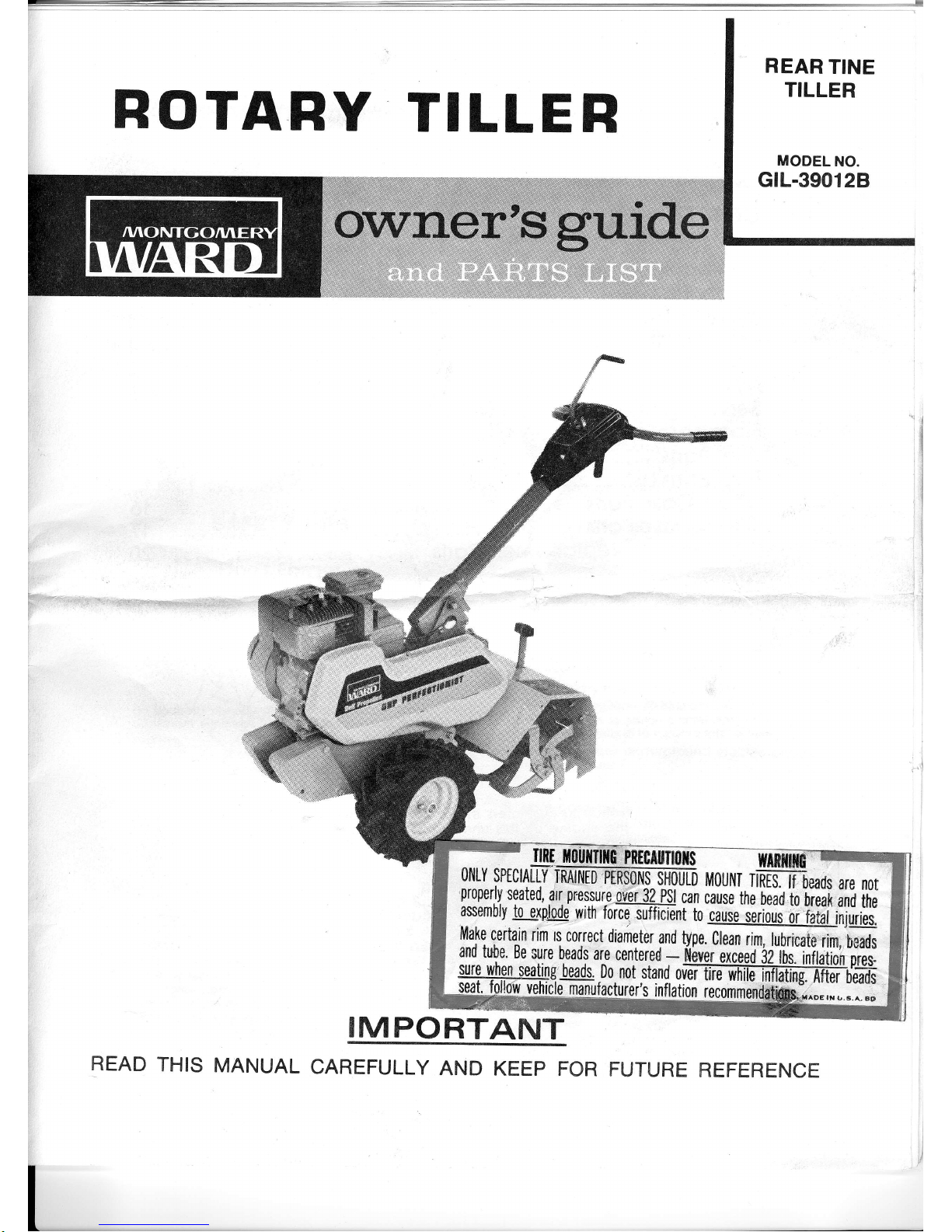
REAR
TINE
TILLER
ROTARY
TILLER
-
ilnlu0uulllc,Pnftfl||r|0tw
orlly
sptctRmW
tvt0tltlr
Tifrffibeads
are
nor
pr'perlv
seated,
arr
pnssure
ovbr
34
pgi
can
ciuie
ttre
ilil
hilert
ffi
ih;
assembly
lq_a\pbde
with
forielullicient
to
artae
iiri,iii
ol
Tiiii'i'ijii.iiii.
Make
certain
rim
rs
correct
diarireter
and
type.G.n
rim,
lubricat0,,rim,
,beads
:l9"t9:8"*1,'"ll'^,^{t,ttt'$eno_fl
ilvgiecotaI$iildiil;hp]"ei:
beads.
.Do
not
stand
ovTrffi
tltffi
tatrng-ffiiffi
:
manufacturer's
inflation
recommendetis["-.^:::,
-.
__
IMPORTANT
READ
THIS
MANUAL
CAREFULLY
AND
KEEP
FOR FUTURE
REFERENCE
GONTENTS
Generol
Introduction
Sofety
Tips
3
3
4
4
5
6
I
11
Initiol
Servicing
Controls
ond
Operotion
Storting
Your
Rotory
Tiiler
Adiustments
Seruicing
Storoge
Tiller
Ports
ond
Mointenqnce
Tiller
Ports
List
12
&14
r3&15
Chqin
Cose
Ports
Choin
Cose
Ports
List
16
17
20
How
to
Order
Replocement
ports
WARNING
IMpoRTANT!
Record
the
unit model
number
ond
its
seriol
number
on the
bock
poge
of this
monuol
for
fulure
reterence
when
ordering
repoir ports
or identificotion
if
unit is
lost
or stolen.
The
monufocturer
reseryes
the
right
lo
mqke
chonges
on
ond
to
odd
improvements
upon
its
products
ol
ony
time
without
notice
or obtigttion.
The
monufqLturer
qiso
resewes
lhe
right
to
discontinue
monufoc-
lure
of ony
product
ot its
discretion
ot ony
iime
Nolice
to
customers
in
lhe
Slofe
of
Colifornio
_
The.engine
on
this
unit
is
trtoT
equipped
with
o
spork
orresting
muffler
USE
OR
OPERATION
OF
THIS
ENGINE
Oil
ANY
lqnEsT
GOVERED,
BBUSH
COVERED
OR
GRASS
COVERED
LAIIID
WITHOUT
A
STATE
APPROVED
SPARK
ABRESTER
IN
EFFECTIVE
WORKIITIG
OR.
DER
COiISTITUTES
A
VIOLATIOil
OF
THE
LAW
OF
THE
STATE
OF
CALIFOBITIIA.
GENERAL
INTRODUCTION
This
Owneis
Guide
hos
been
especiolly
prepored
lo
provide
the
informotion
needed
to
op'eiote
your
tii
ler
with
greoler
sotisfoction.
Reod
this'Owne/i
Guide
ond
the
engine
inslrucfions
corefully.
Be
sure
you
know
whot
the
controls
ore
for
ond
how
they
o[er-
gte:
Ilte
core
your
tiiler
requires
is
smoil,
but'imior_
tont.
Keep
it
cteon
ond
weit
tubricofed.
Witn
prcjber
core
ond
operotion,
os
exploined
in
this
monuof,
you
will
obtoin
long
ond
efficient
service.
This.tiller,
is
.shipped
completely
ossembled.
Afler
reootng
this
monuol
ond
servicing
tiller
the
tiller
is
reody
to
operote.
Informolion
regording
operolion
ond
mointenonce
of
the.engine
is
nol
included
in
this
monuol.
A
sep_
orole
instruction
monuol
is
included
with
your
liller
ond
should
be
consulted
for
oll informoiion
con_
cerning
engine
odjustmenls
ond
operolion.
O Inspect
work
oreo
ond
cleor
ony
objects
thot
ore
not
eorth
or mulch.
o
lmproper
use
of the
rotory
tiller
con resull
in in_
jury.
Give
complete
ond
undivided
ottention
fo
the
work
you
ore
doing.
O
Know
lhe
conlrols
ond
how
they
operote.
o
K.noy
how
to
stop
the
rotory
tiller
ond
engine
in_
stontly.
o
Disengoge
power
ond
stop
engine
before
cleon_
ing,
removing
obstocles,
or
mlking
odjuslment.
a
Keep
children
ond
pets
o
sofe
dislonce
owoy
from
rotory
tiller.
o
Do.
not
ollow
onyone
to
operote
rotory
tiller
with_
out
proper
instruction
ond
supervision.
O
Exercise
coution
to
ovoid
folling.
o
.?on't
sio.rt
the
gngine ond
tines
until
you
ore reocty
lo
slort
tilling.
Stop
the
engine
whenever
you
leov6
the
mochine.
O
Disengoge
clutch
before
slorting
engine.
Keep
honds,
feet
ond
clothing
owoy
from
power_driven
porfs.
Weor
odequoie
footweor
to
prevent
foof
InJury.
O
Keep rotory
tiller
in
good
operoting
condition
ond
keep
sofety
devices
in
ploce.
Do
not
till
neor
underground
electric
cobles
or ir_
rigotion
hoses.
Store
gosoline
in
o
sofe
contoiner.
Store
the
con_
toiner
in
o cool,
dry
ploce.
Not
in
the
house
or
near
heating
appliances.
Open
doors if
engine
is
run
in
goroge.
Exhoust
goses
ore
dongerous.
Fill
gos
tonk
outdoors.
Avoid
spillinq
oosoline.
Don't
fill
lonk
white
engine
is
running
dr inite
you
ore
smoking.
The
replocement
of
ony
porf
on
fhis
product
by
ofher
thon
the
monufocture/s
outhorizdd
reploce_
ment
p.orl
moy
odversely
offect
the
performonce,
durobility
or sofety
of
this
producl.
SAFETY
TIPS
Don't
Forget
thot
SAFETY
storts
with
you!
Yo.ur
rotory
tiller
wos
built
to
the
highest
slondords
in
the
industry.
Howeve_r,
a
rotary
tilleir
is
only
as
safe
as
the
operaror.
As
with
ony
ty-pe
of
powei
equip_
ment,
coretessness
or
error
on
th6
pon
dr the
opeiotbr
con
re.sulf
in injury.
pleose
reoci
ond
follo*
these
Insrructions gn
sofe
operotion
ond
be
cerloin
ony_
one
using
this
rotory
tiller
is
fomilior
with
fhese
sim_
ple
rules:
1.
2.
4.
INITIAL
SERVICING
Before
storling
the
engine,
refer
fo
the
engine
in-
sfructions.
Be
cerloin
lhe
the
engine
cronkcose
is
filled
with
the
proper
type
oil ond thot
oll
en-
gine
service
instructions
hove
been followed
com-
pletely.
Fill
fuel tonk
wilh
o cleon,
fresh,
leod-free
or leod-
ed
"regulor''
grode
of
outomotive
gosoline.
Do
not
mix
oil
with
gosoline.
All nuls
ond bolts
should
be
checked
ond
tight-
ened
during lhe
first
two
(2)
hours
of use.
periodic
checks
should
be mode
thereofler.
The
tires
ore normolly
over-infloted
for
shipping.
The
recommended
lire
pressure
is 20 lbs.
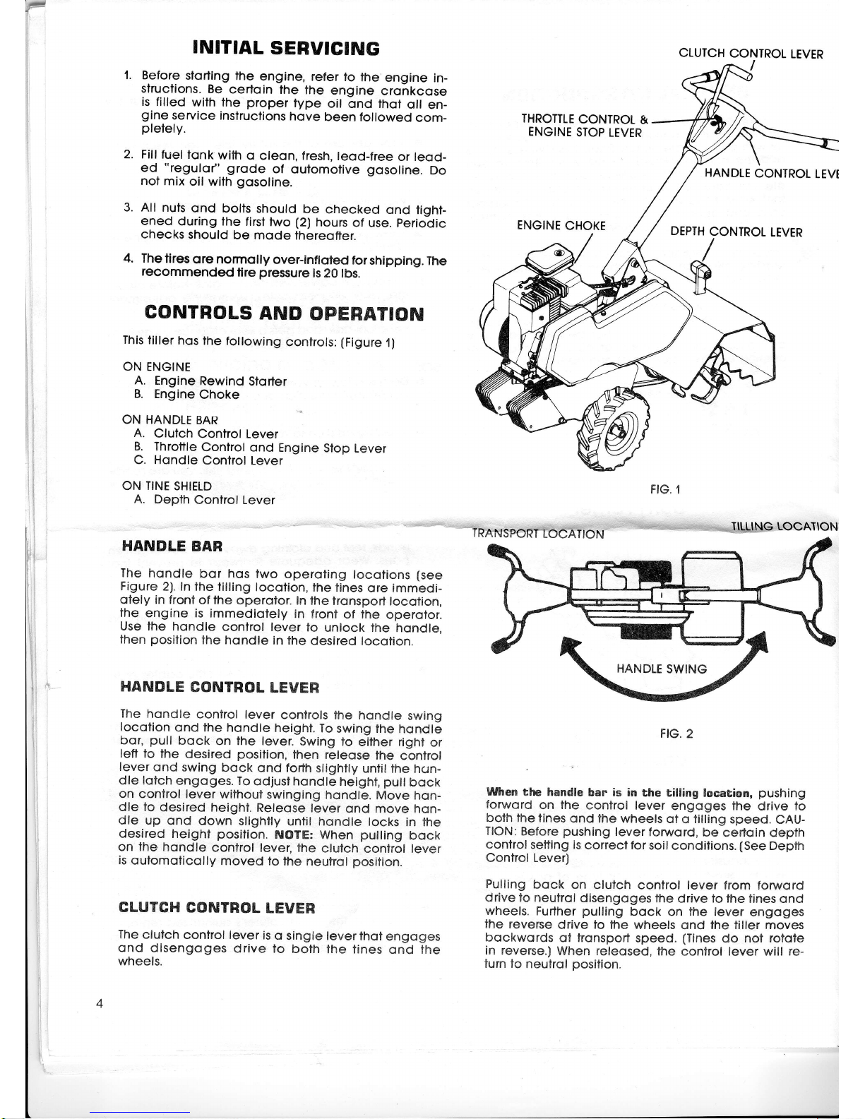
CONTBOLS
AND
OPERATION
This
liller
hos the
following
conlrols:
(Figure
1)
ON
ENGINE
A. Engine
Rewind
Storter
B.
Engine
Choke
ON HANDLE
BAR
A.
Clutch
Control Lever
B.
Throtlle
Control
ond Engine
Slop Lever
C. Hondle
Control
Lever
ON
TINE
SHIELD
A. Depth
Control Lever
HANDLE
BAR
The
hondle
bor
hqs two
operoting
locotions
(see
Figure
2). In the
filling
locotion,
lhe tines
ore
immedi-
otely in front
of the
operotor.
In
lhe tronsport
locotion,
the
engine is
immediotely
in front
of fhe
operofor.
Use lhe
hondle
control
lever
lo
unlock the
hondle,
then
position
the
hondle
in the
desired
locotion.
HANDLE
CONTROL
LEVER
The hondle
control
lever
conlrols
the hondle
swing
locotion
ond
fhe hondle
height.
To
swing the
hqndle
bor,
pull
bock
on the lever.
Swing
lo
either righl
or
lett to
lhe
desired
posilion,
then releqse
the
conlrol
lever
ond swing
bock
ond forth
slighily
unfil
lhe h<.rn-
dle lofch
engoges.
To
odjusl hondle
heighl,
pull
bock
on control
lever
withoul
swinging
hondle.
Move hon-
dle to
desired
heighl.
Releose
lever
ond move
hon-
dle up
ond
down
slightly
unlil hondle
locks
in lhe
desired
height
position.
NOTE:
When
pulling
bock
on the
hondle
conlrol lever,
the
clutch
conirol lever
is
outomoticolly
moved
to
the neutrol
position.
CLUTCH
GONTROL
LEVER
The
clutch
control lever
is
o
single lever
thot
engoges
ond
disengoges
drive to
both
the tines
ond lhe
wheels.
FIG,2
When
the handle
bar is in
the tilling
location,
pushing
forwsrd
on
lhe
control lever
engoges the
drive fo
bolh
the fines
ond the
wheels
ot o tilling
speed.
CAU-
TION:
Before
pushing
lever
forword,
be
cerloin depih
control
setting is
correcf for
soil
conditions.
(See
Depih
Confrol Lever)
Pulling
bock
on clulch
control lever
from forword
drive lo
neutrol
disengoges
the drive to
the tines ond
wheels.
Further
pulling
bock
on lhe lever
engoges
lhe reverse
drive to the
wheels
qnd
the tiller moves
bockwords
ot fronsport
speed.
(Tines
do not
rotote
in reverse.)
When releosed,
the
confrol lever will
re-
lurn to
neutrol
position.
tl
j
i
I
CLUTCH
CONTROL
LEVER
THROTTLE
CONTROL
&
ENGINE
STOP
LEVER
HANDLE
CONTROL
LEVI
ENGINE
CHOKE
DEPTH
CONTROL
LEVER
When
the handle
bar is in
tnansport
location,
fhe
clufch
control
lever
will
only
operofe
by
pulling
the
lever
bock.
This
engoges
the
drive to
the
wheels
ond the
tiller moves
forword
of tronsporl
speed.
When
re-
leosed,
fhe
control lever
refurns
to
neulrol.
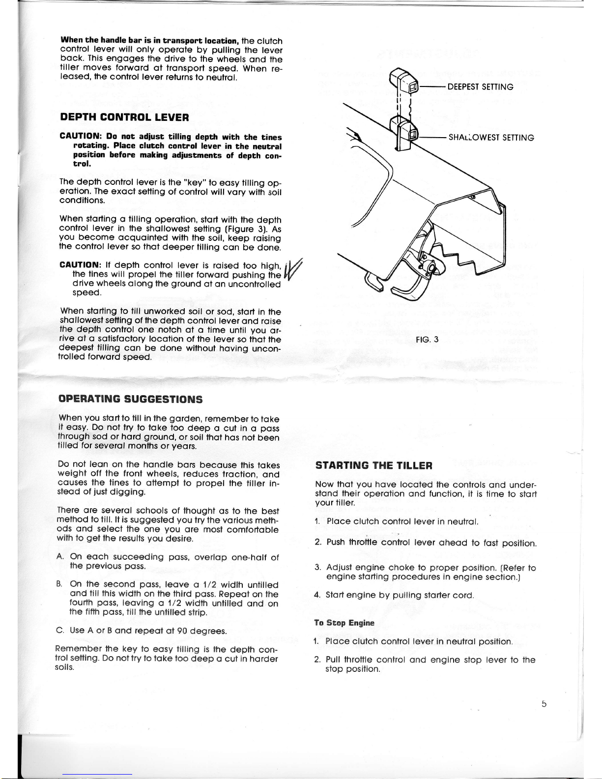
DEPTH
CONTROL
LEVER
GAUTION:
Do nor
adiust
rilling
depth
wfth
rhe tines
rotatang.
Place
clutch
control leyer
in
the neutral
position
before
makhrg
adiustments
of depth
con-
trol.
The
depth
conirol lever
is the
"key"
to
eosy tilling
op-
erotion. The
exoct setting
of
control will
vory
wilh
soil
condilions.
When
storling
o tilling
operotion,
stort with the
depth
confrol lever
in
lhe
shollowesf
setting
(Figure
3).
As
you
become
ocquointed
with
the soil,
keep roising
the
control lever
so thof deeper
tilling
con be done.
CAUTfON: ff
depth
control lever
is roised
loo
high,
iV
the
lines will
propel
the
tiller fonruord
pushing
the
lV
drive wheels
olong
the
ground
of on uncontrolled
speed.
When
sforting to till
unworked
soil
or sod,
sfort in the
shqllowest
setting
of fhe
depth
confrol lever
ond
roise
lhe
depth
control
one notch
ol o time
unlil
you
or-
rive
ol o
sofistocfory
locolion
of
the
lever
so thot the
deepest
tilling
con
be done
without hoving
uncon-
frolled
fonvord
speed.
OPEBATING
SUGGESTIONS
When
you
slortfo till
in the
gorden,
remember
to
toke
it
eosy.
Do
nol lry to
loke too
deep o
cul
in
o
poss
through
sod
or hord
ground,
or soil thot
hos
nol been
tilled for
severol
monfhs
or
yeors.
Do nol leon
on the hondle
bors
becouse
fhis tokes
weight
off the front
wheels, reduces
troction,
ond
couses the tines
to
ottempl
to
propel
the
filler in-
steod of
just
digging.
There
ore severol
schools of thought
os to the
best
method
to
till. lt is
suggested
you
lry
the vorious
meth-
ods ond
select the
one
you
ore
most
comfortoble
with lo
get
lhe resulfs
you
desire.
A.
On eoch succeeding
poss,
overlop
one-holf
of
the
previous
poss.
B.
On the
second
poss,
leove
o 1/2
width
untilled
ond till lhis
width
on lhe third
poss.
Repeot
on ihe
fourth
poss,
leoving
o 1/2 width
untilled ond
on
the
fiflh
poss,
tillthe
untilled
strip.
C. Use A or B
ond repeoi
ot 90
degrees.
Remember
the
key
to eosy tilling
is the
depth
con-
trol
setting. Do
nottry lo toke
loo
deep
o cut in horder
soils.
FIG.
3
STARTING THE
TILLER
Now thot
you
hove locoted
the
controls ond
under-
sfond lheir operotion
ond function, il is
time to
stort
your
tiller.
1. Ploce
clutch
confrol lever in neulrol.
2. Push
throttle
control lever
oheod
to
fosl
position.
3. Adjust
engine
choke
lo
proper posilion.
(Refer
to
engine slorting
procedures
in
engine seclion.)
4.
Slort
engine by
pulling
slorler
cord.
To Stop
Engine
1. Ploce
clutch
control
lever
in neutrol
position.
2. Pull
fhrottle
control ond engine
slop
lever
to the
stop
posilion.
SHAULOWEST
SETTING
ADJUSTMENTS
CAUTION:
Never
ofiempt
to
moke-odjustments
on
fhe
liller
while
the
engine
is
running.
Alwoys
stop
lhe
engine
ond
disconnecl
the
wirelrom
tn6
spoit
plug
before
ottempling
to
moke
odjustments.
BELT
ADJUSTMENTS
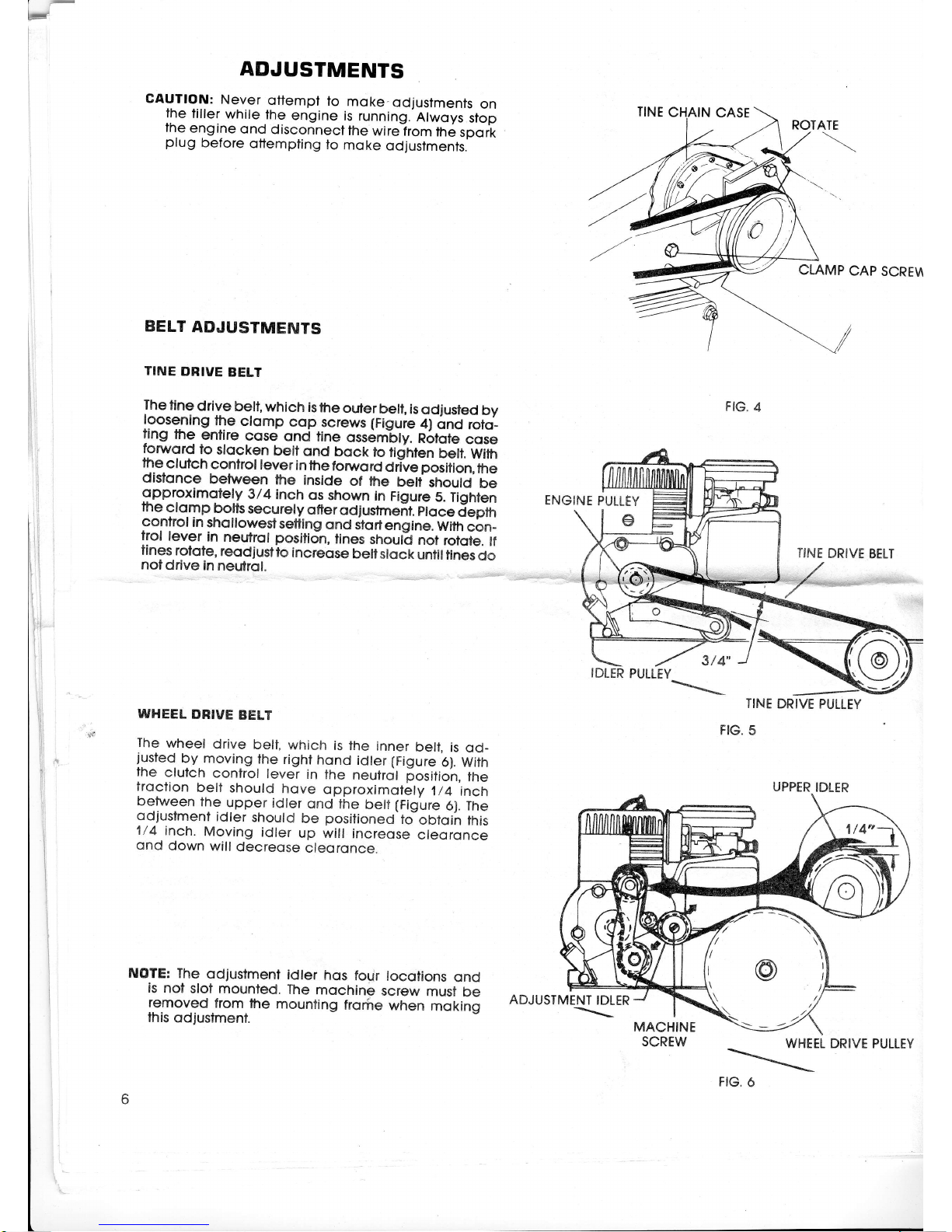
TINE
DBIVE
BELT
The
tine
drive
belt,
which
is
the
outer
be[,
is
odjusted
by
l9_9s9ning
the
ctomp
cop
screws (Figuie
4)
onct
roto_
ang
me
enflre
cose
qnd
tine
ossembly.
R6lote
cose
fonrord
to
stocken
belt
ond
bock
to
fidnten
belt,
With
the
clutch
control
lever
in
the
forword
drlve
position,
the
disfonce
between
the
inside
of fhe
betf
shoutd
be
$Pproximotely
3/4
inch
os
shown
in
Figure
5.
Tighten
the
clo.m
p
bolts
secu
rety
ofter
od
j
ustmeit.
eto
ce
jepm
control
in
shollowestsetting
ond
itortensine.
With
cbn_
trol
lever
in
neutrol
position,
tines
shoult
not
rofote.
lf
flnes
rotote,
reodjustto
increqse
bellslock
untiltines
do
notdrive
in
neutrol.
WHEEL
DRIVE
BELT
The
wheel
drive
belt,
which
is the
inner
beli,
is
od_
justed
by. moving
the
right
hond
idter
(Figure
6).
With
the
clutch
confrol
lever
in
the
neutrcjl
[ositioh,
tfre
troclion
belt
should
hove
opproximoiely
1/4
inch
between
the
upper
idler
ond
the
belf
(Figure
6). The
qdiustment
idler
should
be
positioneO-to
oOtqih
this
1/4
inch.
Moving
idler
up will
increose
cteoronce
ond
down
will
decreose
cleoronce.
ENGINE
PULLEY
c
ADJUSTMENT
IDLER
\
TINE
DRIVE
PULLEY
FIG.
5
CLAMP
CAP
SCRE\A
TINE
DRIVE
BELT
FIG.
4
3t4
NOTE:
The
odjustment
idler
hos
four
locotions
ond
is
nol
sloi
mounted.
The
mochine
screw
must
be
removed
from
the
mounting
frorire
when
moking
this
odjustmenl.
MACHINE
SCREW
WHEEL
\
FIG.
6
ROTATE
UPPER
IDLER
DRIVE
PULLEY
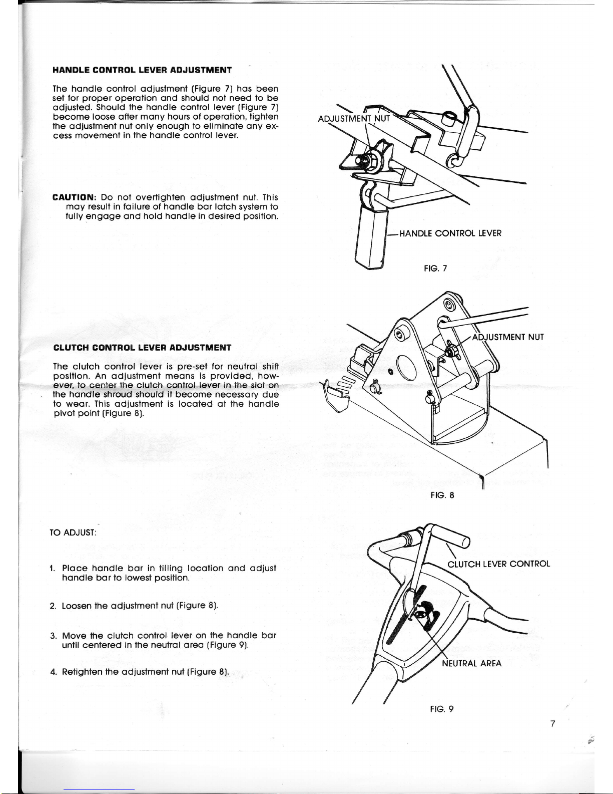
HANDLE CONTROL LEVER
ADJUSTMENT
The hondle
control odjustmenl
(Figure
7) hos been
set
for
proper
operotion ond
should not need to
be
odiusfed.
Should the hondle control lever
(Figure
7)
become
loose ofter
mony hours
of operolion,
tighlen
the
odjustmenl
nul only
enough
lo eliminote ony ex-
cess movement
in the hondle confrol lever.
CAUTION: Do nol overtighlen odjuslmenf nut. This
moy
result
in foilure of hondle bor lotch system lo
fully
engoge ond
hold hondle in
desired
position.
CLUTCH CONTROL LEVER
ADJUSTMENT
The
clutch control
lever is
pre-set
for neutrol
shitt
position.
An odjustmenf
meons is
provided,
how-
ever, lo center the clulch control
lever in
lhe slot on
the hondle shroud should it become necessory
due
to weor. This
odiustmenl
is locoted
ot
fhe hondle
pivol point
(Figure
8)
TO ADJUST:
1. Ploce hondle
bor
in litling locotion ond odjusl
hondle bor to lowesf
posifion.
2. Loosen
the odiustment
nut
(Figure
8).
3.
Move lhe
clutch
control
lever on
the hondle
bor
unfil cenfered
in lhe neutrol oreo
(Figure
9).
4. Retighten fhe odjustmenl nut
(Figure
8).
ADJUSTMENT
NUT
CLUTCH
LEVER CONTROL
NEUTRAL AREA
 Loading...