

Montesa COTA 4RT RACE REPLICA, COTA 4RT-260 Owner's Manual

Important
This motorcycle is designed and constructed as an operator-only model. The motorcycle load limit and seating configuration do not safety permit the carrying
of a passenger.
Read this manual carefully.
This manual should be considered as a permanent part of the motorcycle and should remain with the motorcycle when resold.
Safety Messages
Your safety and the safety of others is very important. We have provided
important safety messages in this manual and on the COTA 4RT. Please read
these messages carefully.
A safety message alerts you to potential hazards that could hurt you or others.
Each safety message is preceded by a safety alert symbol and one of three
words, DANGER, WARNING, or CAUTION.
Significan:
!
DANGER
You WILL be KILLED or SERIOUSLY HURT if you
don’t follow instructions.
!
WARNING
You CAN be KILLED or SERIOUSLY HURT if you
don’t follow instructions.
!
CAUTION
You CAN be HURT if you don’t follow instructions.
Each message tells you what the hazard is, what can happen and what you can
do to avoid or reduce injury.
Damage Prevention Messages
You will also see other important messages that are preceded by the word
NOTICE.
This word means:
NOTICE
Your COTA 4RT or other property can be damaged if you don’t follow
instructions.
The purpose of these messages is to help prevent damage to your COTA
4RT, other property, or the environment.

MONTESA COTA 4RT
Owner’s Manual
The following diagram shows the 4 different versions of the COTA 4RT model:
All information in this publication is based on the latest product information available at the time of approval for printing.
MONTESA HONDA, S.A.U. reserves the right to make changes at any time without notice and without incurring any obligation.
No part of this publication may be reproduced without written permission.
(ED) Street version, COTA 4RT-260 (2E) Street version, COTA 4RT RACE REPLICA
(3E) Racing version, COTA 4RT-260 (4E) Racing version COTA 4RT RACE REPLICA.
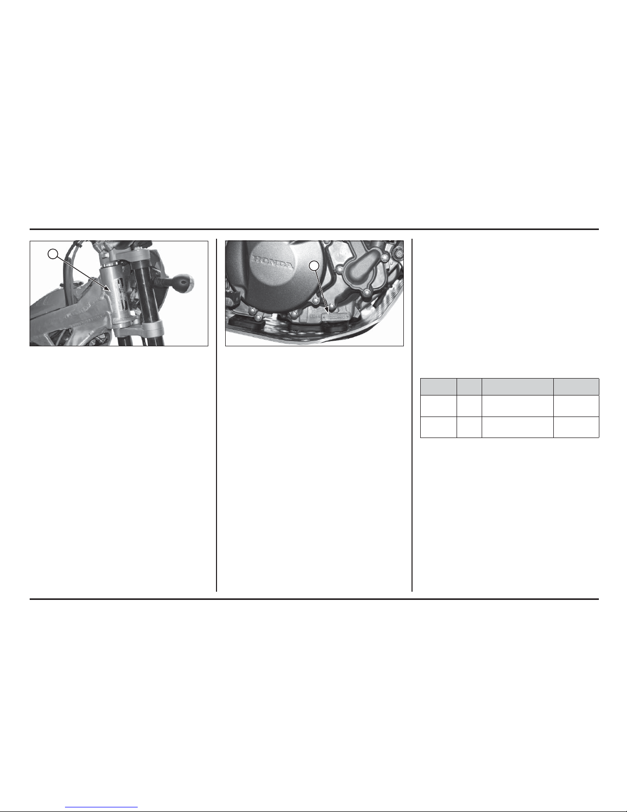
(1) FRAME NUMBER (1) ENGINE NUMBER
Serial numbers
The Vehicle Identification Number (VIN) is stamped on the
right side of the steering head.
The serial number of the engine is stamped on the lower
right side of the crankcase.
MODEL TYPE FRAME No. ENGINE No.
MRT 260 F ED / 2E *VTDMT04F?FE200001* NN4E5201200
MRT 260 F 3E / 4E *VTDMT04C?FE200001* NN4E5201200
1
1

Labels
The following pages show the meanings and locations of the labels on your Cota.
Others provide important safety information. Read this information carefully and don’t remove the labels.
If a label comes off or becomes hard to read, contact your dealer for a replacement.
There is a specific symbol on each label. The meanings of each symbol and label are as follows.
1
Tire information (ED / 2E)
Cold tire pressure (driver only)
Front: 100kpa
Rear: 100kpa
2
Keep chain adjusted and lubricated
25-35 Mm (1.0 -1.4 In)
Read owners manual
3
Caution label
- For yourprotection always wear your helmet while riding.
- Read owner’s manual carefully
- Usepremium unleaded gasoline only.
4
Radiator cap label
Danger
Never open when hot.
Hot coolant will scald you.
Relief pressure valve begins to open at 1.1 Kgf/cm
2
.
5
Safety label (3E / 4E)
6
EC label
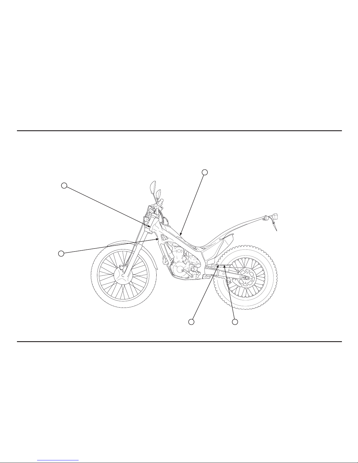
Labels ED / 2E
4
3
21
6
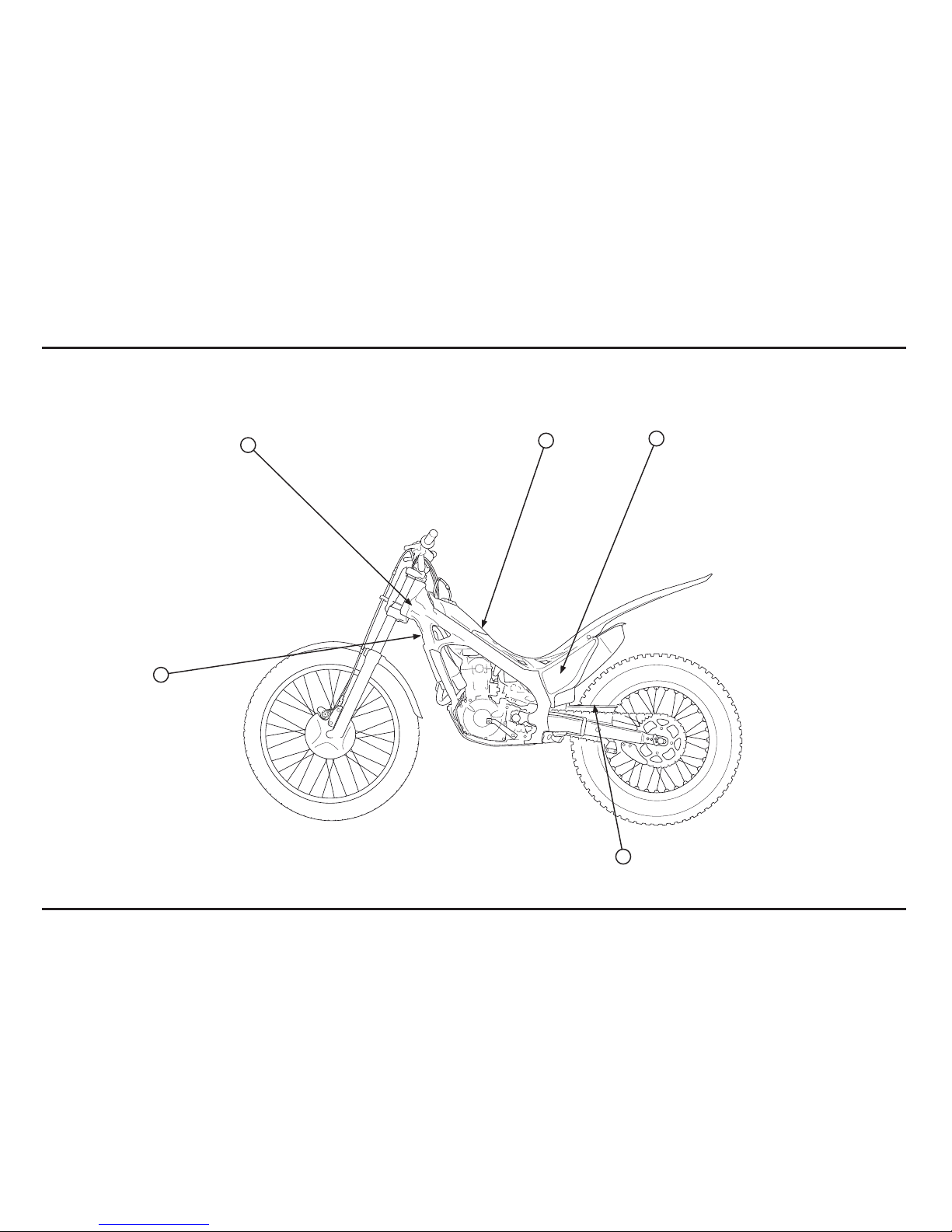
Labels 3E / 4E
4
2
6
5
3

Important Safety Precautions
Your Cota can provide many years of pleasure, if you
take responsibility for your own safety and understand
the challenges you can meet in competitive racing.
As an experienced rider, you know there is much you can
do to protect yourself when you ride.
The following are a few precautions we consider to be
most important.
Never Carry a Passenger.
Your Cota is designed for one operator only.
Carrying a passenger can cause crashes in which you and
others can be hurt.
Wear Protective Gear.
Whether you’re practicing to improve your skills, or riding
in competition, always wear an approved helmet, eye
protection, and proper protective gear.
Take Time to Get to Know Your Cota.
Because every motorcycle is unique, take time to become
thoroughly familiar with how this one operates and
responds to your commands before placing your machine,
and yourself, in competition.
Learn and Respect Your Limits.
Never ride beyond your personal abilites or faster than
conditions warrant. Remember that alcohol, drugs, illness
and fatigue can reduce your ability to perform well and
ride safely.
Don’t Drink and Ride.
Alcohol and riding don’t mix. Even one drink can reduce
your ability to respond to changing conditions, and your
reaction time gets worse with every additional drink. So
don’t drink and ride, and don’t let your friends drink and
ride either.
Keep your Montesa in Safe Condition.
Maintaining your Cota properly is critical to your safety. A
loose bolt, for example, can cause a breakdown in which
you can be seriously injured.
Accessories & Modifications
Modifying your Cota or using non-Montesa accessories
can make your Cota unsafe.
Before you consider making any modifications or adding
an accessory, be sure to read the following information.
!
WARNING
Improper accessories or modifications can cause a
crash in which you can be seriously hurt or killed.
Follow all instructions in this owner’s manual
regarding modifications and accessories.
Accessories
We strongly recommend that you use only Montesa
Genuine accessories that have been specifically designed
and tested for your Cota. Because Montesa cannot test
all other accessories, you must be personally responsible
for proper selection, installation, and use of non-Montesa
accessories.
Check with your dealer for assistance and always follow
this guideline:
Make sure the accessory does not reduce ground clea-
rance and lean angle, limit suspension travel or steering
travel, alter your riding position, or interfere with operating any controls.
Modifications
We strongly advise you not to remove any original
equipment or modify your Cota in any way that would
change its design or operation.
Such changes could seriously impair your Cota’s handling,
stability, and braking, making it unsafe to ride.
General Competition Maintenance
Perform maintenance on firm, level ground using the side
stand, a workstand, or equivalent support.
When tightening bolts, nuts or screws, start with the
larger diameter or inner fasteners, and tighten them to
the specified torque using a crisscross pattern.
Use Montesa Genuine Parts or their equivalent when
servicing your Cota.
Clean parts in non-flammable (high flash point) cleaning
solvent (such as kerosene) when disassembling. Lubricate
any sliding surface, Orings, and seals before reassembling.
Grease parts by coating or filling where specified.
After any engine disassembly, always install new gaskets,
O-rings, cotter pins, piston pin clips, snap rings, etc. when
reassembling. After reassembly, check all parts for proper
installation and operation.

Contents
1. Operating instructions
Operation component locations ...................... 1-1
Fuel ............................................................ 1-2
Coolant ....................................................... 1-2
Basic Operation ............................................ 1-2
Odometer/Speedometer (ED/2E) ..................... 1-4
Steering lock ................................................ 1-4
Shifting gears .............................................. 1-4
Braking ....................................................... 1-5
Parking ........................................................ 1-5
Controls ...................................................... 1-6
2. Service data
Specifications .............................................. 2-1
Service data ................................................. 2-2
Torque Values .............................................. 2-6
Tools .......................................................... 2-8
Lubrication & Seal Points ............................... 2-9
Cable & Harness Routing ............................... 2-12
3. Service and maintenance
Maintenance schedule ................................... 3-1
Pre-ride Inspection ........................................ 3-1
Warming-up Inspection .................................. 3-2
Ride Inspection ............................................. 3-2
After Ride Inspection .................................... 3-2
Replacement Parts ........................................ 3-2
Fuel Line ..................................................... 3-3
Air Cleaner .................................................. 3-3
Spark Plug ................................................... 3-4
Valve Clearance ........................................... 3-4
Engine Oil/Oil Filter ....................................... 3-6
Engine Idle Speed ......................................... 3-8
Transmission Oil ........................................... 3-8
Coolant ....................................................... 3-9
Clutch System ............................................. 3-10
Exhaust Pipe And Muffler .............................. 3-10
Drive Chain .................................................. 3-11
Drive Chain Slider ......................................... 3-11
Drive/Driven Sprockets .................................. 3-12
Brake Fluid .................................................. 3-13
Brake Pad Wear ............................................ 3-14
Brake System ............................................... 3-14
Handlebar And Steering Head Bearings ............ 3-15
Wheels And Tires ......................................... 3-15
Front Suspension .......................................... 3-16
Fork (ED / 3E) .............................................. 3-16
Fork (2E /4E)
................................................ 3-17
Rear Suspension ........................................... 3-18
Front headlight and front and rear position light. 3-19
Cleaning ...................................................... 3-20
Storage ....................................................... 3-20
4. Engine servicing
Oil Pressure Relief Valve ................................ 4-1
Oil Pump ..................................................... 4-1
Fuel Line Inspection ...................................... 4-4
Fuel Tank/Fuel Pump ..................................... 4-6
Injector ....................................................... 4-9
Throttle Body ............................................... 4-10
Water Seal And Bearing Replacement .............. 4-12
Radiator Removal/Installation ......................... 4-14
Cylinder Compression ................................... 4-17
Cylinder Head Removal ................................. 4-20
Cylinder Head Disassembly ............................ 4-22
Cylinder Head Inspection ............................... 4-23
Valve Guide Replacement .............................. 4-24
Valve Seat Inspection/Refacing ...................... 4-25
Cylinder Head Assembly ................................ 4-28
Cylinder/Piston ............................................. 4-29
Cylinder Head Installation .............................. 4-34
Right Crankcase Cover .................................. 4-37
Clutch Slave Cylinder .................................... 4-38
Clutch ......................................................... 4-40
Kickstarter ................................................... 4-43
Gearshift Linkage .......................................... 4-44
Left Crankcase Cover .................................... 4-46
Flywheel ..................................................... 4-49
Crankcase Separation/Disassembly ................. 4-51
Crankshaft/Transmission Inspection ................ 4-53
Crankcase Bearing Replacement ..................... 4-53
Transmission Assembly ................................. 4-55
Crankcase Combination ................................. 4-56
5. Frame servicing
Front Wheel ................................................. 5-1
Fork ............................................................ 5-3
Steering stem .............................................. 5-12
Rear Wheel .................................................. 5-15
Shock Absorber ............................................ 5-16
Shock Linkage .............................................. 5-20
Swingarm .................................................... 5-21
Brake pad replacement .................................. 5-25
Front brake caliper ........................................ 5-28
Rear brake caliper ......................................... 5-29
Front master cylinder .................................... 5-30
Rear master cylinder ..................................... 5-31
Brake pedal .................................................. 5-31
Clutch master cylinder .................................. 5-32
6. Electrical servicing
Charging system inspection ........................... 6-1
Ignition system inspection ............................. 6-3
PGM-FI System inspection ............................. 6-5
PGM-FI ........................................................ 6-6
PGM-FI Self-diagnosis malfunction
indicator lamp (mil) failure codes .................... 6-7
Bank angle sensor inspection ......................... 6-8
Engine stop switch inspection ........................ 6-9
Cooling fan system inspection ........................ 6-9
Chapter lights / instruments / switches ............ 6-10
Speed sensor ............................................... 6-14
Battery ........................................................ 6-15
Wiring diagram (ED / 2E) ............................... 6-16
Wiring diagram (3E / 4E) ................................ 6-17

How To Use This Manual
The purpose of this Owner’s Manual is to help ensure that
you obtain the greatest possible satisfaction from your
new COTA trialer; satisfaction with the performance of
the motorcycle, and through success in competition.
If you plan to do any service on your COTA, section 3
describes standard maintenance and sections 4 through
6 contain in information on repair, disassembly, assembly
and special tools.
Follow the Maintenance Schedule recommendation (page
3-1) to ensure that your COTA is always in peak operating
condition.
Importance Of Proper Preparation
Proper pre-competition preparation and regular service
is essential to rider safety and the reliability of the
motorcycle. Any error or oversight made by the technician
during preparation or servicing can easily result in faulty
operation, damage to the machine, or injury to the rider.
Parts Availability
Orders for the parts tend to be concentrated during the
season, so you need to plan your parts orders carefully.
To prevent delays in shipment, place orders on regularly
replaced and fast-wearing parts well ahead of the season
(see page 3-2).
To The New Owner
By selecting a MONTESA COTA 4RT as your new
machine, you have placed yourself in a distinguished
family of owners and riders.
The COTA is a high performance trial motorcycle utilizing
the latest trial technology. This motorcycle is intended for
competition use by experienced riders only.
This new trialer was designed to be as competitive as
possible. But motorcycle trial is a physically demanding
sport that requires more than just a fine racing machine.
To do well, you must be in excellent physical condition
and be a skillful rider. For the best possible results, work
diligently on your physical conditioning and practice
frequently.
The purpose of this Manual is to help ensure that you
obtain the greatest possible satisfaction from your new
COTA trialer.
Start-up recommendations
Adjusting the idle
If using your motorcycle at different heights, bear in mind
that you must adjust the idle; otherwise, you may have
problems operating the vehicle. (See page 3-8)
Engine start
If you have problems starting your vehicle, follow the
steps below:
1. Open the throttle all the way (100%) and hold.
2. Without releasing the throttle, operate the kick-starter
once or twice.
3. Close the throttle and start your motorcycle as normal.

Memo
1-1
1-1
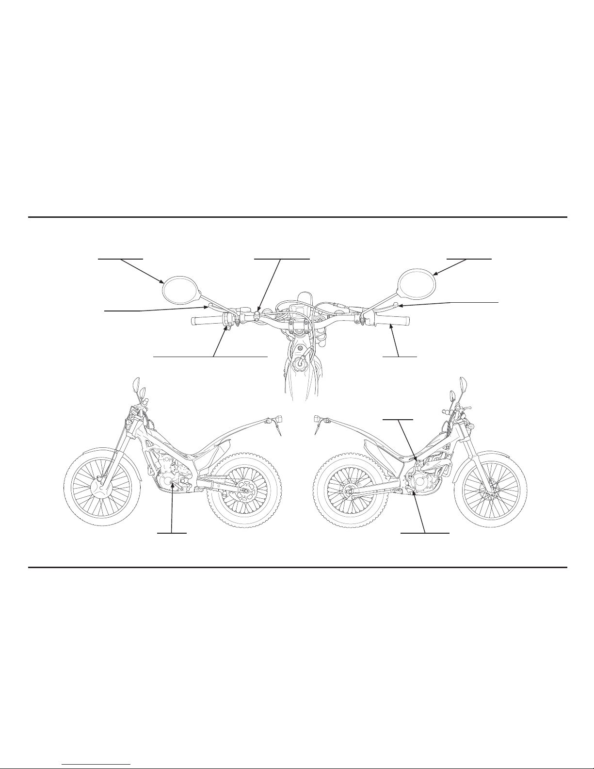
1. Operating instructions
Operation component locations
front brake lever
throttle grip
engine stop buttonrearview mirror rearview mirror
shift lever
kickstarter
Rear brake pedal
light control, turn signal & horn switch
clutch lever
Operating instructions
1-2
1-2
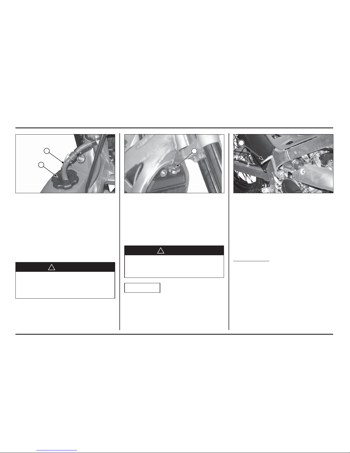
(1) BREATHER HOSE
(2) FUEL TANK CAP
(1) RADIATOR CAP (1) KICKSTARTER PEDAL
Fuel
Gasoline: Premium unleaded gasoline (commercially
available unleaded; pump octane number 91
or higher)
Fuel tank capacity: 1.9 liter (0.5 US gal, 0.4 Imp gal)
Disconnect the fuel tank breather hose clamp from the
clutch hose.
Turn the fuel tank cap counterclockwise, then remove the
cap.
!
WARNING
Gasoline is highly flammable and is explosive.
You can be burned or seriously injured when refueling.
Stop engine and keep heat, sparks, and flame away.
Refuel only outdoors.
Wipe up spills immediately.
Install the fuel tank cap by turning it clockwise.
Install the breather hose clamp onto the clutch hose.
Coolant
The engine of COTA is a water-cooled type. In order to
provide adequate cooling, it is essential that the radiator
be filled with coolant up the proper level (See pag. 3-9).
Coolant: 50/50 Mixture of Coolant and Distilled Water
!
WARNING
Removing the radiator cap while the engine is hot will
allow the coolant to spray out, seriously scalding you.
Always let the engine and radiator cool down before
removing the radiator cap.
NOTICE
When fi lling the coolant system, be sure to bleed air
completely. If not, the system cannot be suffi ciently fi lled
and will cause overheating.
Basic Operation
Starting The Engine
Your COTA exhaust contains poisonous carbon monoxide
gas. High levels of carbon monoxide can collect rapidly in
enclosed areas such as a garage. Do not run the engine
with the garage door closed. Even with the door open,
run the engine only long enough to move your COTA out
of the garage.
Cold Engine Starting
1. Shift the transmission into neutral.
2. With the throttle fully closed, operate the kickstarter.
Starting from the top of the kickstarter stroke, kick
through to the bottom with a rapid, continuous motion.
3. After the engine starts, run it for a few minutes, “blipping” the throttle, until it warms up enough to idle.
1
1
1
2
Operating instructions
1-3
1-3
Break-In Procedure
New Motorcycle
Following proper break-in procedure helps ensure that
the most important and expensive components on your
new motorcycle will provide maximum performance and
service life. (Also follow proper break-in procedure for a
newly rebuilt engine.)
When riding a new motorcycle, operate the motorcycle
for the first 20 minutes using not more than half throttle
and shifting gears so that the engine does not lug:
Reconditioned Motorcycle
After replacing the cylinder and crankshaft, operate the
motorcycle 20 minutes observing the same cautions as
for a new motorcycle.
When the piston, piston ring, gears, etc. are replaced,
they must be broken in observing the first 30 minutes
using not more than half throttle and shifting gears so
that the engine does not lug
When you shift the transmission into gear, apply front
brake to prevent the motorcycle move forward.
Stopping The Engine
1. Shift the transmission into neutral.
2. Push the engine stop button until the engine stops
completely.
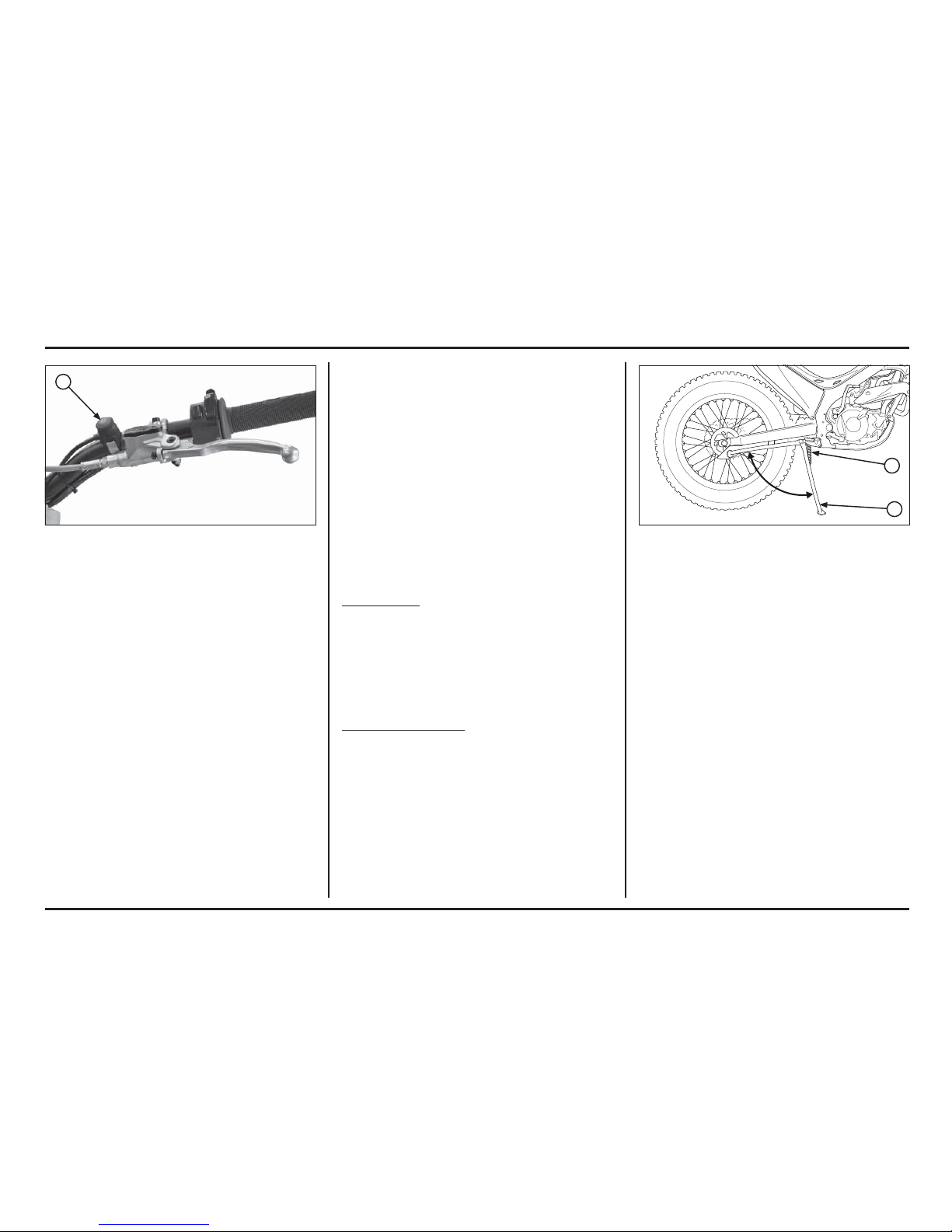
(1) ENGINE STOP BUTTON
1
2
1
(1) SIDE STAND
(2) SIDE STAND SPRING
Side Stand
The side stand is used to support your Cota while parked.
To operate, use your foot to lower the side stand until it
is fully extended.
Before riding, raise the side stand.
Inspection
1. Check the side stand spring for damage and loss of
tension.
2. Check the side stand assembly for freedom of
movement.
If the side stand is stiff or squeaky, clean the pivot area
and lubricate the pivot bolt with grease.

Operating instructions
1-4
1-4
1
4
3
2
1
ED / 2E
ED / 2E
(1) SPEEDOMETER
(2) TURN SIGNAL INDICATOR
(3) HIGH BEAM INDICATOR
(4) ODOMETER
Odometer/Speedometer (ED/2E)
Instruments and indicators
The indicators are located in the speedometer.
The display has two functions, odometer and speedometer.
Speedometer: Shows riding speed. This shows your
speed in kilometers per hour
(km/h).
Odometer: Shows accumulated mileage.
High beam indicator (blue): Lights when the headlight
is on high beam
Right turn signal indicator (green): Flashes when the
right turn signal operates.
Left turn signal indicator (green): Flashes when the left
turn signal operates.
(1) STEERING LOCK
Steering lock
The steering lock is on the steering stem. To lock the
steering, turn the handlebar all
the way to the left, insert the steering key into the lock,
turn the key counterclockwise
as far as possible. Then, press the lock all the way in, turn
the key back to the original
position, and remove the key.
To unlock the steering, perform the locking sequence in
the reverse order.
Shifting gears
Your Cota has five forward gears in a one-down, four-up
shift pattern.
To start riding, after the engine has been warmed and the
side stand raised.
1. Close the throttle and pull the front brake lever in.
2. Pull the clutch lever all the way in.
3. Depress the shift lever from neutral down to first gear.
4. Release the front brake lever. Gradually open the
throttle while you slowly release the clutch lever. If the
engine min-1 (rpm) (speed) is too low when you release
the clutch lever, the engine will stall.
If the engine min-1 (rpm) (speed) is too high or you
release the clutch lever too quickly, your Cota may
lurch forward.
5. When you attain a moderate speed, close the throttle,
pull the clutch lever in, and raise the shift lever. After
shifting, release the clutch lever and apply the throttle.
6. To continue shifting up to each higher gear, repeat step 5.
7. To shift down to a lower gear, close the throttle, pull
the clutch lever in, and depress the shift lever. After
shifting, release the clutch lever and apply the throttle.
Operating instructions
1-5
1-5
Braking
To slow or stop, apply the front brake lever and rear brake
pedal smoothly, while downshifting to match your speed.
Gradually increase braking as you feel the brakes slowing
your speed. To prevent stalling the engine, pull the clutch
lever in before coming to a complete stop. For support,
put your left foot down first, then your right foot when
you are through using the rear brake pedal.
For maximum braking, close the throttle and firmly apply
the front brake lever and rear brake pedal controls.
Applying the brakes too hard may cause the wheels to
lock and slide, reducing control of your Cota. If this happens, release the brake controls, steer straight ahead until
you regain control, then reapply the brakes more gently.
Generally, reduce your speed or complete braking before beginning a turn. Avoid braking or closing the throttle
quickly while turning. Either action may cause one or both
wheels to slip. Any wheel slip will reduce your control of
your Cota.
When riding in wet or raining conditions, or on loose surfaces, the ability to maneuver and stop will be reduced.
All of your actions should be smooth under these conditions. Rapid acceleration, braking, or turning may cause
loss of control. For your safety, exercise extreme caution
when braking, accelerating, or turning.
When descending a long, steep grade, use engine compression braking by downshifting, with intermittent use
of both brakes.
When you brake to a stop, pull the clutch lever in before
stopping completely to prevent stalling the engine. For
support, put your left foot on the ground first, then your
right foot when you have finish braking.
Remember to close the throttle and pull the clutch lever in
completely before shifting.
NOTICE
Improper shifting may damage the engine, transmission,
and drive train.
Learning when to shift gears comes with experience.
Upshift to a higher gear or reduce throttle before engine
min-1 (rpm) (speed) gets too high. Downshift to a lower
gear before you feel the engine laboring (lugging) at low
min-1 (rpm).
NOTICE
Downshifting can help slow your motorcycle, especially
on downhills. However, downshifting when engine min-1
(rpm) is too high can cause engine damage.
NOTICE
To prevent transmission damage, do not coast or tow the
motorcycle for long distances with the engine off.
Parking
Lower the side stand to support your Cota.
Always choose a level surface to park.
Operating instructions
1-6
1-6
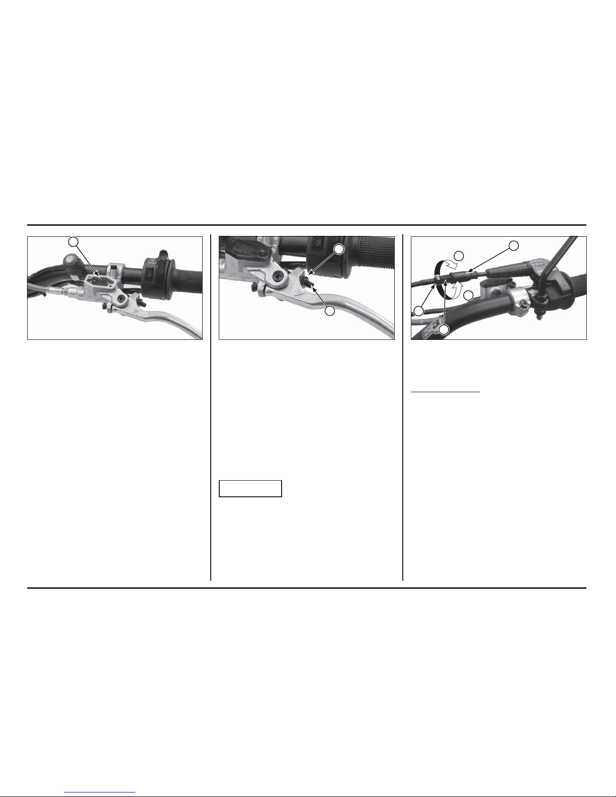
Throttle Grip
Throttle Grip Free Play
Standard throttle grip free play is approximately 3 mm
(0.12 in) of grip rotation.
Adjustment is made with the integral throttle cable
adjuster.
Slide the dust cover off from the integral cable adjuster.
Turning the adjuster in direction “A” will decrease free
play and turning it in direction “B” will increase free play.
Tighten the lock nut after adjustment.
Operate the throttle grip to ensure that it functions
smoothly and returns completely in all steering position.
(1) DUST COVER (A) DECREASE
(2) LOCK NUT (B) INCREASE
(3) ADJUSTER
Clutch Lever
The clutch lever free play can be adjusted by turning the
adjuster.
Free play must be adjusted to provide 0.1 – 1.4 mm
(0.004 – 0.055 in) clearance between the end of the
adjuster and the clutch master cylinder piston.
To increase free play, turn the adjuster clockwise, then
tighten the lock nut securely.
If the clutch lever free play exceeds 30 mm (1.2 in) even
though the end of the adjuster and the clutch master
cylinder piston is adjusted to the minimum of 0.1 mm
(0.004 in), there is probably air in the clutch system and
it must be bled.
NOTICE
Do not adjust the end of the adjuster and the clutch master cylinder piston below 0.1 mm (0.004 in).
(1) ADJUSTER
(2) LOCK NUT
Controls
Clutch
Your COTA has a hydraulically actuated clutch. There are
no adjustments to perform but the clutch system must be
inspected periodically for fluid level and leakage.
If the control lever free play becomes excessive and the
motorcycle creeps or stalls when shifted into gear, or if
the clutch slips, causing acceleration to lag behind engine
speed, there is probably air in the clutch hydraulic system
and it must be bled out.
(1) UPPER LEVEL LINE
1
A
B
2
3
1
1
2
Operating instructions
1-7
1-7
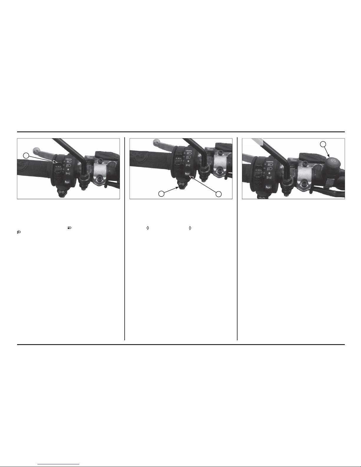
(1) HEADLIGHT DIMMER SWITCH
(2) PASSING LIGHT CONTROL SWITCH
(1) TURN SIGNAL SWITCH
(2) HORN BUTTON
Headlight dimmer switch
Push the dimmer switch to
to select high beam or to
to select low beam.
Turn signal switch
Move to
to signal a left turn, to signal a right turn.
Press to turn signal off.
Horn button
Press the button to sound the horn.
(1) ENGINE STOP BUTTON
Emergency engine stop
To stop the engine in an emergency, push and hold the
engine stop button.
1
ED / 2E
ED / 2E
ED / 2E
ED / 2E
1
2
1
ED / 2E
ED / 2E
Operating instructions
1-8
1-8
Handlebar position, width and shape
Position the handlebar so that gripping the bar and operating the controls is comfortable while both seated and
standing, while riding straight ahead and turning.
Handlebar width can be trimmed with a hacksaw to better
your particular shoulder width and riding preference. Think
this though carefully and cut off just a small amount at a
time from both side equally. It is obviously much easier
to make the handlebar narrower than it is to add material.
NOTICE
Chamfer the edges to remove burrs and other irregularities or roughness after shaping.
An alternate handlebar shape. through varying rise or
rearward sweep dimensions, will provide further adjustment to riding position and may better suit your particular body size or riding style. Each of the ergonomic
dimensions of the motorcycle were determined to suit the
greatest possible number of riders based on an average
size rider.
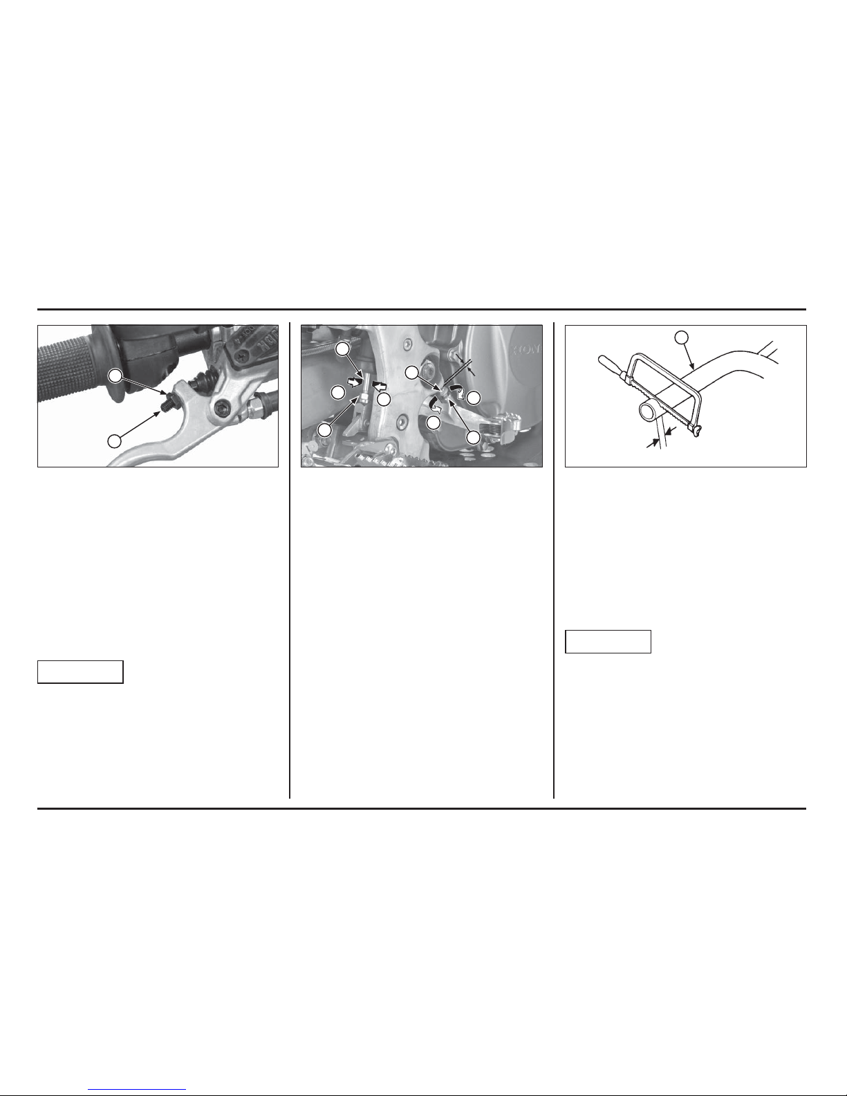
(1) HANDLEBAR(1) LOCK NUT
(2) ADJUSTING BOLT
(A) RAISE THE PEDAL HEIGHT
(B) LOWER THE PEDAL HEIGHT
Brake pedal height
The brake pedal height can be adjusted to the rider’s preference.
To adjust the rear brake pedal height:
1. Loosen the push rod lock nut and brake pedal adjusting
bolt lock nut. Then turn the both adjusting bolts in
direction “A” to raise the pedal, or in direction “B” to
lower it.
2. Tighten the lock nuts at the desired pedal height.
3. After adjustment, check the brake pedal free play at
the top of the pedal.
Make sure that the clearance between the front adjus-
ting bolt and frame is at least 1 mm (0.04 in).
Front brake lever
The front brake lever free play can be adjusted by turning
the adjuster.
Free play must be adjusted to provide 0.1 – 1.4 mm
(0.004 – 0.055 in) clearance between the end of the adjuster and the front brake master cylinder piston.
To increase free play, turn the adjuster clockwise, then
tighten the lock nut securely.
If the brake lever free play exceeds 30 mm (1.2 in) even
though the end of the adjuster and the front brake master
cylinder piston is adjusted to the minimum of 0.1 mm
(0.004 in), there is probably air in the brake system and
it must be bled.
NOTICE
Do not adjust the end of the adjuster and the front brake
master cylinder piston below 0.1 mm (0.004 in).
(1) ADJUSTER
(2) LOCK NUT
A
A
B
B
1
1
2
2
1
1
2
2. Service data
Specifications
Item Specification
Dimensions
Overall length
Overall width
Overall height
Wheelbase
Seat height
Ground clearance
2,020 mm
840 mm
1,135 mm
1,320 mm
679 mm
300 mm
Frame
Type
Front suspension
Rear suspension
Front tire
Rear tire
Front brake, diameter
Rear brake, diameter
Fuel capacity
Caster angle
Trail length
Aluminium twin tube
Telescopic
Swingarm PRO-LINK
DUNLOP D803F
(2,75-21 M/C 45M)
MICHELIN TRIAL COMPETITION
(2,75-21 M/C 45L)
DUNLOP D803
(4.00 R18 M/C 64M)
MICHELIN TRIAL COMPETITION X11
(4.00 R18 M/C 64L)
Single disc, 183 mm
Single disc, 150 mm
1,9 litres
24º 34’
63 mm
Engine
Type
Cylinder arrangement
Bore and stroke
Displacement
Compression ratio
Valve timing
Intake valve opens
Intake valve closes
Exhaust valve opens
Exhaust valve closes
Lubrication system
Starting system
Liquid cooled 4–stroke engine
Single cylinder, 3.5˚ inclined from vertical
78,0 x 54,2 mm
259 cm3
10,5 : 1
9˚ BTDC
27˚ ABDC
37˚ BBDC
5˚ ATDC
Forced pressure and wet sump
Primary kickstarter
Item Specification
Fuel System
Type
Identification number
Throttle bore
PGM-FI
GQPCA
29,4 mm
Drive Train
Clutch operating system
Clutch type
Transmission
Primary reduction
Gear ratio 1st
2nd
3rd
4th
5th
Final reduction
Gearshift pattern
Hydraulic operated
Wet, multi-plate
5 speed constant mesh
3,167 (57/18T)
2,800 (42/15T)
2,385 (31/13T)
2,000 (30/15T)
1,273 (28/22T)
0,815 (22/27T)
4,100 (41/10T)
1 – N – 2 – 3 – 4 – 5
Electrical
Alternator
Ignition system
Regulator type
Triple phase output alternator
PGM-IGN
SCR shorted/triple phase, full wave rectification
(at 1.0 mm lift)
2-1
2-1
Service data
2-2
2-2
Service data
Item Specification
Lubrication
Specified engine oil Repsol 4T oil-stroke motorcycle oil SAE 10W-30
Engine oil capacity
after draining 0.41 liter (0.43 US qt, 0.36 Imp qt)
after oil filter change 0.44 liter (0.46 US qt, 0.39 Imp qt)
after disassembly 0.60 liter (0.63 US qt, 0.53 Imp qt)
Specified transmission oil ELF HTX740
Transmission oil capacity
after draining 0.54 liter (0.57 US qt, 0.48 Imp qt)
after disassembly 0.57 liter (0.60 US qt, 0.50 Imp qt)
Fuel System
Throttle body identification No. GQPCA
Throttle grip free play 3 mm (0.1 in)
Engine idle speed 1,800 ± 100 min-1 (rpm)
Fuel pressure 294 kPa (2,99 kgf/cm2) at idle
Fuel pump flow at 12 V 138 cm3 minimum/10 seconds
Injector resistance 11.1 – 12.3 Ω (20˚C/68˚F)
Cooling System
Recommended coolant 50/50 mixture coolant and distilled water
Radiator cap relief pressure 108 kPa (1,1 kgf/cm
2
)
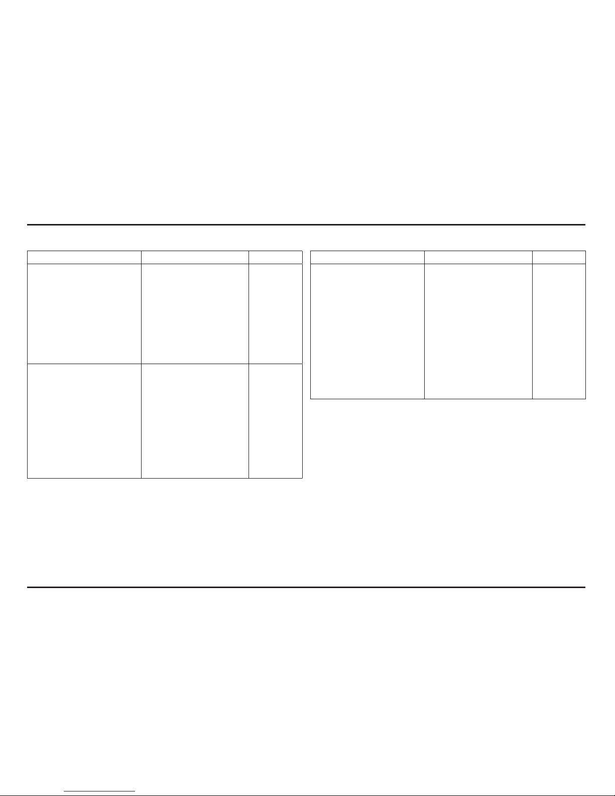
Item Standard Service limit
Cylinder Head/Valves
Cylinder compression 460 kPa (4,7 kgf/cm2) –
Cylinder head warpage – 0,05 (0,002)
Valve clearance IN 0,12 ± 0,03 (0,005 ± 0,001) –
EX 0,30 ± 0,03 (0,012 ± 0,001) –
Valve stem O.D. IN 4,475 – 4,490 (0,1762 – 0,1768) 4,470 (0,1760)
EX 4,465 – 4,480 (0,1758 – 0,1764) 4,460 (0,1756)
Valve guide I.D. IN/EX 4,500 – 4,512 (0,1772 – 0,1776) 4,552 (0,1792)
Valve stem-to-guide clearance
IN 0,010 – 0,037 (0,0004 – 0,0015) –
EX 0,020 – 0,047 (0,0008 – 0,0019) –
Valve guide projection IN 8,0 – 8,3 (0,31 – 0,33) –
above cylinder head EX 8,2 – 8,5 (0,32 – 0,33) –
Valve spring free length Inner 25,41 (1,000) 24,9 (0,98)
Outer 28,32 (1,115) 27,6 (1,09)
Rocker arm I.D. 10,000 – 10,015 (0,3937 – 0,3943) 10,051 (0,3957)
Rocker arm shaft O.D. 9,972 – 9,987 (0,3926 – 0,3932) 9,925 (0,3907)
Rocker arm-to-shaft clearance 0,013 – 0,043 (0,0005 – 0,0017) 0,11 (0,04)
Cam lobe height IN 32,011 – 33,051 (1,2603 – 1,3012) 31,871 (1,2548)
EX 32,855 – 32,935 (1,2935 – 1,2967) 32,748 (1,2893)
Unit: mm (in)

Service data
2-3
2-3
Item Standard Service limit
Cylinder/Piston
Cylinder I.D 78,000 – 78,015 (3,0709 - 3,0715) 78,04 (3,0724)
Taper – 0,05 (0,002)
Out-of- round – 0,05 (0,002)
Warpage – 0,05 (0,002)
Piston O.D. 77,970 – 77,980 (3,0696 - 3,07008) 77,89 (3,0665)
Measurement point
5 (0,2) from bottom of skirt
–
Pin bore I.D. 16,002 – 16,008 (0,6300 – 0,6302) 16,03 (0,631)
Piston pin O.D. 15,994 – 16,000 (0,6297 – 0,6299) 15,98 (0,629)
Piston ring
End gap
Top 0,15 – 0,25 (0,008 - 0,0098425) 0,39 (0,01535)
Second 0,30 – 0,45 (0,012 - 0,0018) 0,59 (0,02323)
Oil (side rail) 0,20 – 0,70 (0,008 – 0,028) 0,90 (0,035)
Ring-to-groove clearance
Top 0,065 – 0,100 (0,0026 – 0,0039) 0,115 (0,0045)
Second 0,015 – 0,050 (0,0006 – 0,0020) 0,065 (0,0026)
Cylinder-to-piston clearance 0,020 – 0,045 (0,0008 – 0,0018) 0,18 (0,007)
Piston-to-piston pin clearance 0,002 – 0,014 (0,0001 – 0,0006) 0,04 (0,002)
Connecting rod small end I.D. 16,016 – 16,034 (0,6305 – 0,6313) 16,04 (0,631)
Clutch/Gearshift Linkage
Recommended clutch fluid DOT 4 brake fluid –
Clutch spring free length 27,6 (1,09) 26,8 (1,06)
Clutch disc thickness 3,22 – 3,38 (0,127 – 0,133) 3,15 (0,124)
Clutch plate warpage – 0,10 (0,004)
Clutch slave cylinder I.D. 27,000 – 27,021 (1,0630 – 1,0638) –
Clutch slave piston O.D. 26,940 – 26,960 (1,0606 – 1,0614) –
Kickstarter
Spindle O.D. 16,466 – 16,484 (0,6483 – 0,6490) 16,46 (0,648)
Pinion gear I.D. 16,516 – 16,534 (0,6502 – 0,6509) 16,55 (0,652)
Idle gear I.D. 17,016 – 17,034 (0,6699 – 0,6706) 17,06 (0,672)
Countershaft O.D.
at kickstarter idle gear 16,983 – 16,994 (0,6686 – 0,6691) 16,97 (0,668)
Item Standard Service limit
Crankshaft/Transmission
Crankshaft runout Right – 0,03 (0,001)
Left – 0,05 (0,002)
Connecting rod big end
Side clearance 0,30 – 0,75 (0,012 – 0,030) 0,8 (0,03)
Radial clearance 0,06 – 0,18 (0,002 – 0,007) 0,05 (0,002)
Transmission gear I.D. M4 23,020 – 23,041 (0,9063 – 0,9071) 23,07 (0,908)
M5 23,020 – 23,041 (0,9063 – 0,9071) 23,07 (0,908)
C1 20,020 – 20,041 (0,7882 – 0,7890) 20,06 (0,790)
C2 25,020 – 25,041 (0,9850 – 0,9859) 25,06 (0,987)
C3 25,020 – 25,041 (0,9850 – 0,9859) 25,06 (0,987)
Gear bushing D.I. M5 20,000 – 20,021 (0,7866 – 0,7882) 20,05 (0,789)
C1 17,000 – 17,018 (0,6693 – 0,6700) 17,04 (0,671)
C2 22,000 – 22,021 (0,8661 – 0,8670) 22,04 (0,868)
C3 22,000 – 22,021 (0,8661 – 0,8670) 22,04 (0,868)
O.D. M4 22,979 – 23,000 (0,9047 – 0,9055) 22,96 (0,904)
M5 22,979 – 23,000 (0,9047 – 0,9055) 22,96 (0,904)
C1 19,979 – 20,000 (0,7866 – 0,7874) 19,95 (0,785)
C2 24,979 – 25,000 (0,9834 – 0,9843) 24,95 (0,982)
C3 24,979 – 25,000 (0,9834 – 0,9843) 24,95 (0,982)
Countershaft O.D.
at C1 bushing 16,983 – 16,994 (0,6686 – 0,6691) 16,97 (0,668)
at C2/C3 bushing 21,959 – 21,980 (0,8645 – 0,8654) 21,94 (0,864)
at kickstarter idle gear 16,983 – 16,994 (0,6686 – 0,6691) 16,97 (0,668)
Shift fork I.D. C 11,003 – 11,024 (0,4332 – 0,4330) 11,04 (0,435)
R, L 12,035 – 12,056 (0,4738 – 0,4746) 12,07 (0,475)
Shift fork claw thickness C 4,93 – 5,00 (0,194 – 0,197) 4,8 (0,19)
R, L 4,93 – 5,00 (0,194 – 0,197) 4,8 (0,19)
Shift fork shaft O.D. C 10,983 – 10,994 (0,4324 – 0,4328) 10,97 (0,432)
R, L 11,966 – 11,984 (0,4711 – 0,4718) 11,95 (0,470)
Oil pump
Tip clearance – 0,20 (0,008)
Body clearance 0,15 – 0,20 (0,006 – 0,008) –
Side clearance 0,05 – 0,12 (0,002 – 0,004) –
Unit: mm (in) Unit: mm (in)
Service data
2-4
2-4
Unit: mm (in)
Item Standard Service Limit
Wheels/Tires
Axle runout 0.20 (0.008)
Tire air pressure
*Comptetion use only Front (1) 39 – 44 kPa (0,40 – 0,45 kgf/cm
2
)–
Rear (1) 29 – 34 kPa (0,30 – 0,35 kgf/cm
2
)–
Wheel rim runout Radial – 2.0 (0,08)
Axial – 2,0 (0,08)
Drive chain slack 25 – 35 (1,0 – 1,4) –
Drive chain slider thickness –
2.0 (0.08) from
upper surface
Front Suspension TECH (ED/3E)
Left fork spring free length 390 (15,35) 382 (15,04)
Fork tube runout 0,35 – 0,50 (0,014 – 0,020) 0,20 (0,008)
Recommended fork fluid TECH OJ 01
Pre-load adjuster setting 5±0,5 turns out from full soft –
Damping adjuster setting Tension adjuster: –
20±2 clicks from full hard –
Fork oil level Right 50 (1,96) –
Left 100 (3,93) –
Fork oil capacity Right 400 cm
3
–
Left 410 cm
3
–
Unit: mm (in)
Item Standard Service Limit
Front Suspension SHOWA (2E/4E)
Left fork spring free length 384,8 (15,14) 377,1 (14,85)
Fork tube runout 0,35 – 0,50 (0,014 – 0,020) 0,20 (0,008)
Recommended fork fluid Showa SS05
Pre-load adjuster setting 7±0,5 turns out from full soft
–
Damping adjuster setting Compression adjuster: 0,065 (0,0026)
17±2 clicks from full hard –
Tension adjuster: 0,04 (0,002)
20±2 clicks from full hard –
Fork oil level Right 38 (1,5) –
Left 87 (3,4) –
Fork oil capacity Right 405 cm
3
–
Left 410 cm
3
–
Service data
2-5
2-5
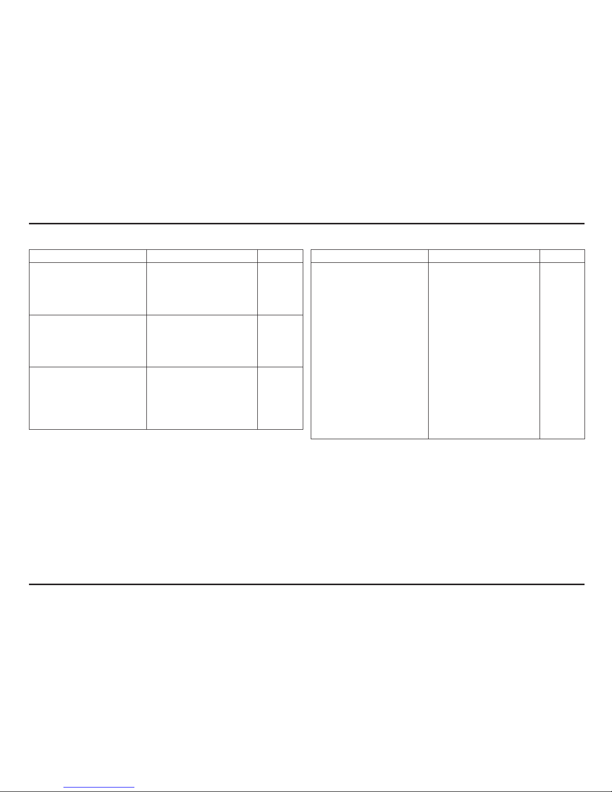
Unit: mm (in)
Item Standard Service Limit
Rear Suspension R16V (ED/3E)
Shock absorber spring pre-load 126 (4,96) –
Spring free length 130 (5,1) –
Nitrogen gas pressure 1,35 Mpa (13,76 kgf/cm2)–
Tension adjuster setting 12±2 clicks from full hard –
Rear Suspension
SHOWA (2E/4E)
Shock absorber spring pre-load 126,5 (4,98) –
Spring free length 133 (5,2) 130,3 (5,13)
Nitrogen gas pressure 1,27 Mpa (13 kgf/cm
2
)–
Tension adjuster setting 10±2 clicks from full hard –
Brakes
Recommended brake fluid DOT 4 brake fluid –
Front Brake disc thickness 3,5 (0,14) 3,0 (0,12)
Brake disc runout – 0,15 (0,006)
Rear Brake disc thickness 2,5 (0,10) 2,0 (0,08)
Brake disc runout – 0,15 (0,006)
Unit: mm (in)
Item Standard Service Limit
Electrical
Spark plug Standard NGK: CR6EH-9 –
Spark plug gap 0,80 – 0,90 (0,031 – 0,035) –
Ignition coil resistance
Primary 2,6 -3,2 Ω (20º C) –
Secondary with plug cap 17,3 -22,8 kΩ (20º C) –
Secondary without plug cap 13,5 – 16,5 KΩ (20º C) –
Ignition pulse generator
Resistance 85 -115 Ω (20º C) –
Alternator
Regulated voltage 13,5 – 14,5 V/1,800 min-1 (rpm) –
Charging coil resistance 0,7 -1,0 Ω (20º C) –
ECT sensor resistance 2,3 -2,6 kΩ (20º C) –
Bulbs
Headlight 12V – 35/35 W –
Position light 12V – 4 W –
Brake/tail light 12V – 21/5 W –
Turn signal light 12V – 10 W X 4 –
Cuentakilómetros 12V –
Service data
2-6
2-6
Torque Values
Standard
Item
Torque
N•m (kgf•m, Ibf•ft)
5 mm bolt and nut 5 (0,52, 3,5)
6 mm bolt and nut 10 (1,0, 7)
8 mm bolt and nut 22 (2,2, 16)
10 mm bolt and nut 33 (3,4, 25)
12 mm bolt and nut 53 (5,4, 40)
5 mm screw 4 (0,42, 3)
6 mm screw and flange bolt (SH type) 9 (0,9, 7)
6 mm flange bolt and nut 12 (1,2, 9)
8 mm flange bolt and nut 26 (2,7, 20)
10 mm flange bolt and nut 38 (3,9, 29)
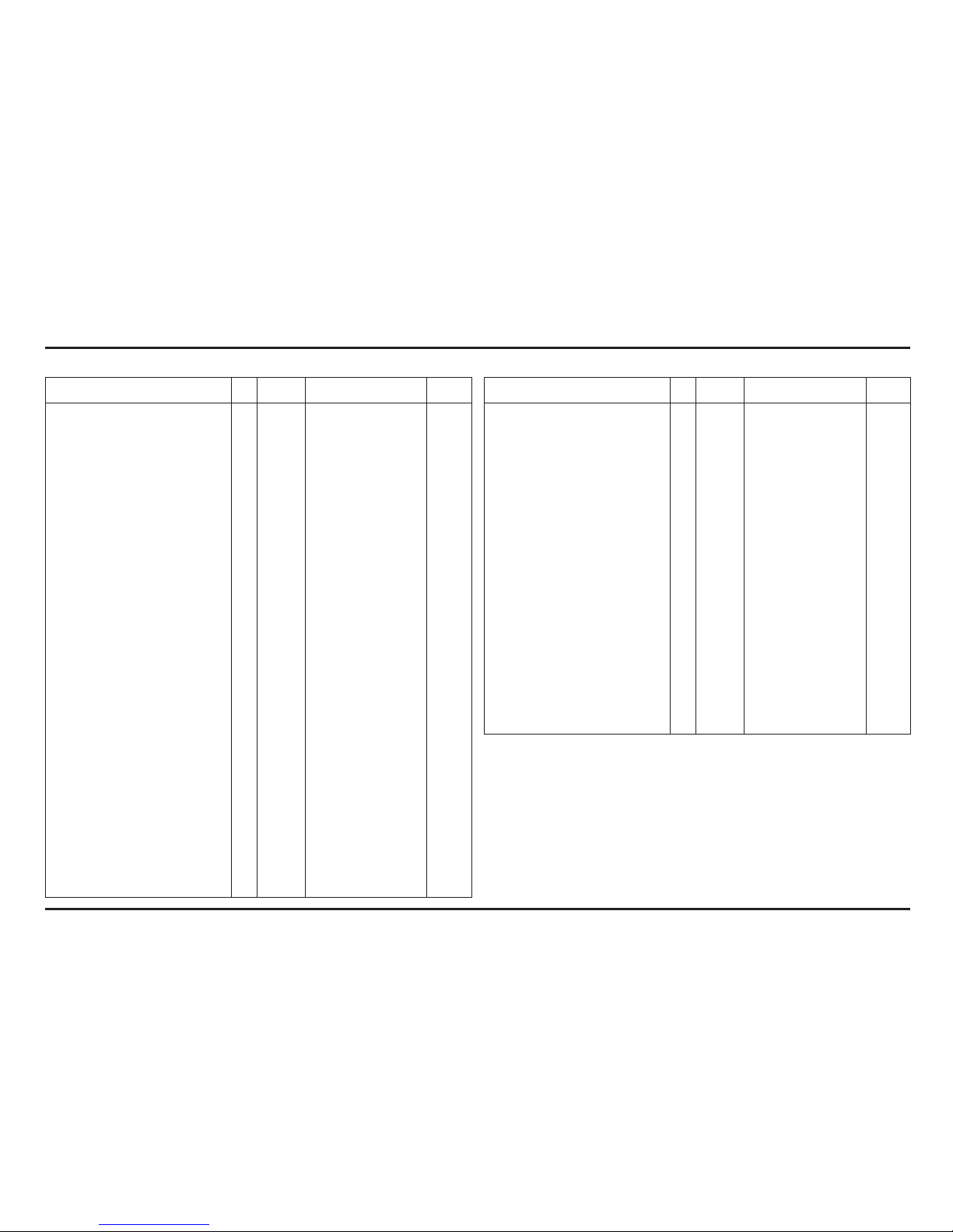
Engine
Item Q’ty
Thread
Dia. (mm)
Torque
N•m (kgf•m, Ibf•ft)
Remarks
Transmission oil drain bolt 1 8 22 (2.2, 16) Note 1
Engine oil drain bolt 1 8 22 (2.2, 16) Note 1
Right crankcase cover joint pipe 1 18 18 (1.8, 13) Note 2
Timing hole cap 1 14 7 (0.7, 5.1) Note 3
Bearing set plate socket bolt 4 6 9.8 (1.0, 7) Note 4
Bearing set plate screw 2 6 12 (1.2, 9) Note 4
Bearing set plate flat screw 2 6 9.8 (1.0, 7) Note 4
Cylinder head sealing bolt 1 12 32 (3.3, 24) Note 4
Cylinder head mounting nut 2 9 39 (4.0, 29) Note 1
Cylinder head joint pipe 1 18 18 (1.8, 13) Note 2
Vacuum port joint 1 5 2.5 (0.25, 1.8)
Primary drive gear special bolt 1 12 108 (11.0, 80) Note 1
Flywheel nut 1 18 167 (17.0, 123) Note 1
Cam chain tensioner bolt 1 6 12 (1.2, 9) Note 4
Valve clearance adjusting nut 4 6 14 (1.4, 10) Note 1
Injector holder socket bolt 2 6 9.8 (1.0, 7)
Fuel hose banjo bolt (holder side) 1 18 24 (2,4, 17,7)
Water pump impeller 1 7 12 (1.2, 9)
Clutch oil bleeder screw 1 8 6 (0.6, 4.3)
Clutch spring bolt 6 6 12 (1.2, 9)
Clutch center lock nut 1 18 69 (7.0, 51) Note 1
Drive sprocket UBS bolt 1 8 31 (3.2, 23)
Shift drum center special bolt 1 8 22 (2.2, 16) Note 4
Shift drum stopper arm bolt 1 6 12 (1.2, 9)
Shift return spring pin 1 8 22 (2.2, 16)
Ignition pulse generator bolt 2 5 5.4 (0.55, 4.0) Note 4
Stator mounting bolt 3 5 5.4 (0.55, 4.0) Note 4
Spark plug 1 10 16 (1.6, 12) Note 2
Notes: 1. Apply clean engine oil to the threads and seating surface.
2. Apply sealant to the threads.
3. Apply grease to the threads.
4. Apply a locking agent to the threads.
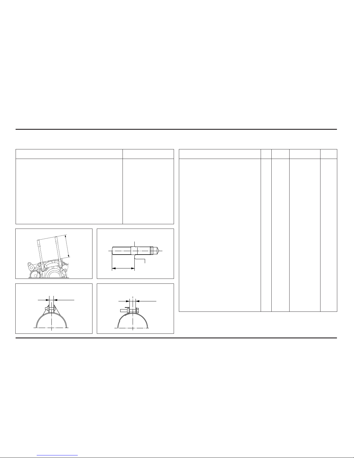
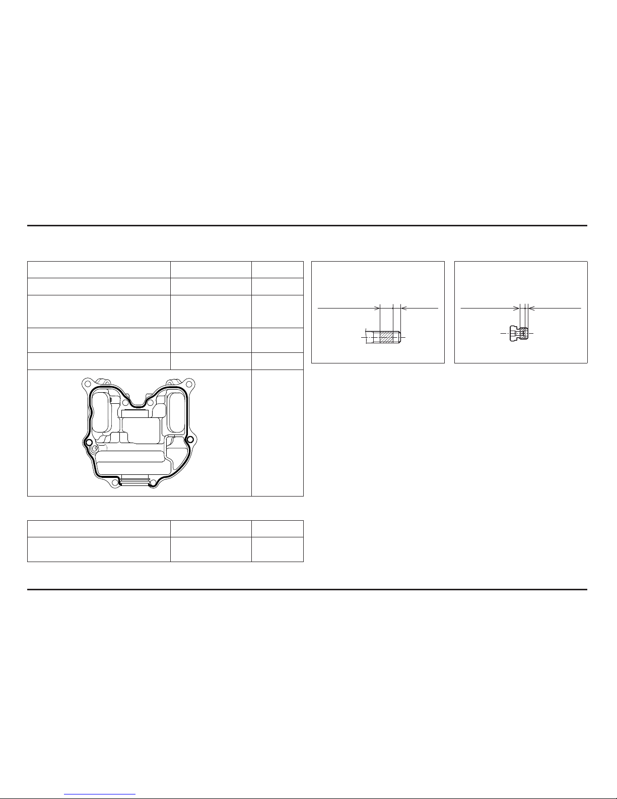
Cylinder stud bolt:
Insulator band (cylinder head side):
Exhaust pipe stud bolt:
Insulator band (throttle body side):
101,5±1mm
17±0,5mm
7±1mm
7±1mm
Service data
2-7
2-7
Frame
Item Q’ty
Thread
Dia. (mm)
Torque
N•m (kgf•m, Ibf•ft)
Remarks
Brake pedal pivot bolt 1 8
29 (3,0, 22)
Note 2
Steering head top thread 1 26
5 (0,5, 3,6)
Note 1
Steering stem nut 1 20 99 (9,9, 73) Note 1
Clutch hose (master cylinder) 1 10 20 (2,0, 14)
Rear master cylinder mounting bolt 2 6 8 (0,8, 5,8)
ECT sensor 1 12 15 (1,5, 11)
Fuel hose banjo bolt:
Fuel pump side 1 12 22 (2,2, 16)
Fuel pump mounting bolt 6 5 7 (0,7, 5,1)
Front spoke nipple 32 BC 3,5 4,9 (4,9, 3,6)
Rear spoke nipple 32 4 3 (0,2 - 0,3)
Shock absorber spring lock nut 1 50 49 (5,0, 36)
Shock arm bolt/nut 1 10 39 (4,0, 29)
Shock link bolt/nut 2 10 39 (4,0, 29)
Clutch oil bleeder bolt 1 10 23 (2,3, 17)
Rim lock nut 1 8 13 (1,3, 9)
Fork cap 2 36 23 (2,3, 17)
Fork cap bolt-to-adjuster case 1 22 34 (3,5, 25)
Fork adjuster case lock nut 1 10 20 (2,0, 14)
Right fork center bolt (ED/3E) 1 14 14,7 (1,47, 13) Note 2
Right fork center bolt (2E/4E) 1 14 34 (3,5, 25) Note 2
Left fork center bolt (ED/3E) 1 15 24,5 (2,45, 18) Note 2
Left fork center bolt (2E/4E) 1 15 34 (3,5, 25) Note 2
Notes: 1. Apply grease to the sliding surface.
2. Apply a locking agent to the threads.
Item Q’ty
Thread
Dia. (mm)
Torque
N•m (kgf•m, Ibf•ft)
Remarks
Handlebar holder bolt 4 8 22 (2,2, 16) Note 1
Front axle 1 17 69 (7,0, 51) Note 1
Rear axle 1 17 69 (7,0, 51) Note 1
Final driven sprocket nut (ED/2E) 4 8 24-30 (2,4-3,0, 17,7-22,1) Note 3
Final driven sprocket nut (3E/4E) 4 8 30-35 (3,0-3,5, 22,1-25,8) Note 3
Shock absorber:
Upper mounting bolt/nut 1 10 39 (4,0, 29) Note 4
Lower mounting bolt/nut 1 10 39 (4,0, 29) Note 4
Fork top pinch bolt 2 8 21 (2,1, 15,4) Note 1
Fork bottom pinch bolt 4 8 21 (2,1, 15,4) Note 1
Swingarm pivot nut 1 14 69 (7,0, 51) Note 1
Front brake disc mounting bolt 4 6 18-20 (1,8-2,0, 13-15) Note 2
Rear brake disc mounting bolt 4 6 16-18 (1,6-1,8, 11-13) Note 2
Side stand pivot nut 1 10 23 (2,3, 17)
Side stand bracket mounting bolt 2 8 26 (2,7, 20) Note 2
Exhaust pipe flange bolt 1 6 12 (1,2, 9) Note 1
Engine hanger:
Upper hanger bolt/nut 1 8 24 (2,4, 17)
Front hanger bolt 1 10 49 (5,0, 36) Note 1
Down tube mounting bolt 4 8 25 (2,6, 19) Note 1
Front axle holder bolt 2 6 23 (2,3, 17) Note 1
Skid plate:
Front mounting bolt 2 8
26 (2,7, 20)
Throttle housing bolt 2 5
4,2 (0,43, 3,1)
Note 4
Clutch lever holder bolt 2 5
3,2 (0,33, 2,4)
Front brake master cylinder 1 8
22 (2,2, 16)
holder bolt 2 6
3,2 (0,33, 2,4)
Note 4
Front brake caliper mounting bolt 2 8
26 (2,7, 20)
Note 2
Brake hose:
Front master cylinder 1 10
27 (2,8, 20)
Front caliper 1 10
27 (2,8, 20)
Rear master cylinder 1 10
27 (2,8, 20)
Rear brake caliper 1 10
27 (2,8, 20)
Service data
2-8
2-8
Tools
Special
Description Tool number Applicability
Bearing remover, 12 mm 07936–1660101 Water pump bearing
– Remover shaft 07936–1660120
– Remover weight 07741–0010201
Water seal driver 07945–KA30000 Water seal
Attachment, 28 x 30 mm 07946–1870100 Water pump bearing
Clutch center holder 07JMB–MN50301 Clutch center lock nut
Fork seal driver set 07947–4630100 Fork oil seal
Fork damper holder 89515–NN3–821 Right fork socket bolt
Fork damper holder 07930–KA50100 Left fork socket bolt
Ball race remover 07948–4630100 Stem bearing race
Steering stem driver 07946–4300000 Stem lower bearing
Bearing driver 07946–KA50000 Swingarm pivot bearing
Bearing remover 07946–MJ00100 Shock link needle bearing
Swingarm link bearing
Spherical bearing driver 07HMF–KS60100 Shock absorber bearing
Snap ring pliers 07914–3230001 Master cylinder snap ring
* Flywheel holder 89020–NN4–003 Flywheel
* Flywheel puller 89010–NN4–003 Flywheel
Compressor attachment 07959–MB10000 Shock absorber spring
* Newly designed tool for this model.
Description Tool number Applicability
Spoke nipple wrench 07701–0020300 Front spoke nipple
Gear holder 07724–0010100 Primary drive gear bolt
Bearing remover head 07746–0050600 Wheel bearing
Bearing remover shaft 07746–0050100 Wheel bearing
Driver 07749–0010000 Bearing removal/installation
Attachment, 24 x 26 mm 07746–0010700 Swingarm pivot bearing
Attachment, 32 x 35 mm 07746–0010100 Right countershaft bearing
Left mainshaft bearing
Attachment, 37 x 40 mm 07746–0010200 Left shift drum bearing
Attachment, 42 x 47 mm 07746–0010300 Right mainshaft bearing
Left countershaft bearing
Right shift drum bearing
Wheel bearing
Ball race
Attachment, 52 x 55 mm 07746–0010400 Crankshaft oil seal
Attachment, 62 x 68 mm 07746–0010500 Left crankshaft bearing
Attachment, 72 x 75 mm 07746–0010600 Right crankshaft bearing
Pilot, 12 mm 07746–0040200 Water pump bearing
Pilot, 17 mm 07746–0040400 Right countershaft bearing
Left mainshaft bearing
Pilot, 20 mm 07746–0040500 Left countershaft bearing
Wheel bearing
Swingarm pivot bearing
Pilot, 22 mm 07746–0041000 Right mainshaft bearing
Pilot, 25 mm 07746–0040600 Right shift drum bearing
Pilot, 30 mm 07746–0040700 Right crankshaft bearing
Pin spanner 07702–0020001 Shock spring adjuster
(2 required)
Shock absorber compressor 07GME–0010100 Shock absorber spring
Common
Service data
2-9
2-9
Lubrication & Seal Points
Engine
Item Material Remarks
Crankcase sealing bolt threads and
seating surface
Cylinder bore inner surface
Cylinder head nut threads and
seating surface
Piston pin bore and outer surface
Piston pin outer surface
Piston ring surface
Crankshaft oil seal lips
Decompressor weight sliding
surface
Valve adjusting nut threads
Oil pump rotor sliding surface
Clutch outer sliding surface
Clutch friction disc surface
Clutch center nut threads and
seating surface
Clutch lifter piece needle bearing
area
Primary drive gear bolt threads and
seating surface
Shift drum grooves
Gearshift spindle serration
Flywheel nut threads and seating
surface
Each bearing
Each O-ring
Crankcase inside (transmission oil) ELF HTX740 570 cm
3
Crankcase inside (engine oil) Repsol 4T-stroke engine oil
10W-30
600 cm
3
Item Material Remarks
Connecting rod small end I.D. Molybdenum oil solution
Connecting rod big end (A 50/50 mixture of
Camshaft outer surface molybdenum disulfide
Rocker arm I.D. grease and engine oil
Valve stem sliding surface
Valve stem end sliding surface
Clutch outer collar sliding surface
Mainshaft spline and gear sliding surface
Countershaft spline and gear sliding surface
Shift fork I.D. and gear contact area
Shift fork shaft surface
Kickstarter spindle spline area and gear sliding
surface
Each gear
Right crankshaft bearing set plate bolt threads Locking agent 6.5 ± 1 mm
Right mainshaft bearing/shift drum bearing set plate
bolt threads
Left coutershaft bearing set plate bolt threads 3.5 ± 1 mm
Left crankcase sealing bolt threads
Cylinder mounting bolt threads
Cylinder head sealing bolt threads 6.5 ± 1 mm
Cam chain tensioner bolt threads 6.5 ± 1 mm
Shift drum center bolt threads
Ignition pulse generator bolt threads
Stator mounting bolt threads
Service data
2-10
2-10
Item Material Remarks
Clutch slave cylinder piston/O-ring Silicone grease
Left crankcase cover cap threads
Each oil seal lips
Water seal lips
Lithium based multipurpose
grease
Right crankcase cover water hose joint threads
Cylinder head water hose joint threads
Sealant
Cylinder head cover mating surface Three Bond 1215B
Wheel
Item Material Remarks
Rear wheel nipple Locking agent
Candar C73R
Only versions
(ED/3E)
Chain tensioner bolt transmission Drain hole
Application zone
6.5±1 mm
Application zone
2.5±1 mm3 - 4 mm 1.2±0.4 mm

Service data
2-11
2-11
Frame
Item Material Remarks
Steering head bearing race and bearings
Steering head dust seal lips
Swingarm pivot needle bearing
Swingarm pivot dust seal lips
Shock link/shock arm needle bearings
Shock link/shock arm dust seal lips
Kickstarter arm joint sliding
Brake lever pivot sliding surface
Side stand pivot sliding surface
Brake pedal pivot sliding surface
Chain tensioner roller bearings
Clutch lever pivot sliding surface
Wheel bearing spinning area
Wheel axle threads
Step joint pin surface
Multi-purpose grease
Throttle pipe sliding surface and throttle wire drum 4-stroke engine oil
Throttle housing screw threads Molybdenum disulfide grease
Brake hydraulic system inside
Clutch hydraulic system inside
DOT 4 brake fluid
Air cleaner element Engine oil
Throttle cable sliding surface Cable lubricant
Handlebar grip Honda bond A or equivalent
Item Material Remarks
Drive chain adjuster stopper screw threads
Side stand bracket bolt threads
Steering stopper bolt threads
Drive chain slider mounting screw threads
Rear brake hose clamp screw threads
Cooling fan nut threads
Locking agent
Service data
2-12
2-12
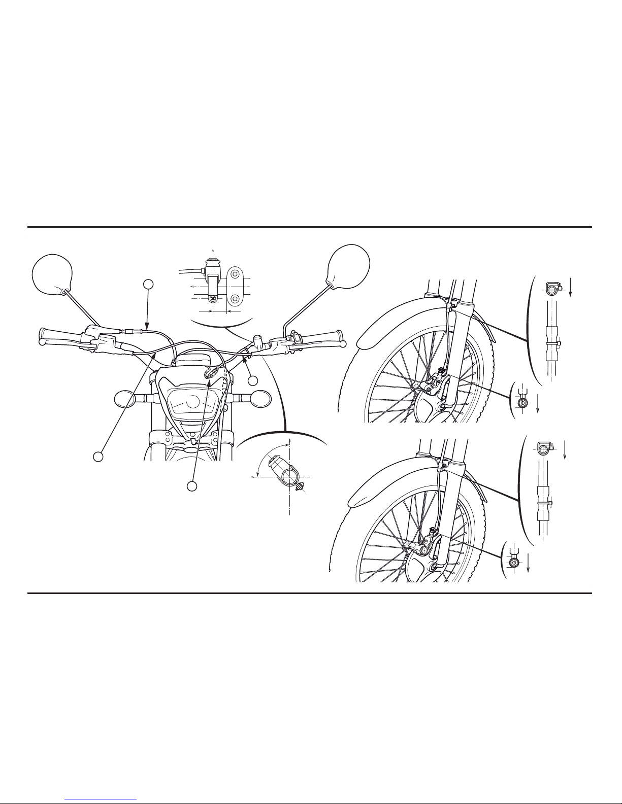
Cable & Harness Routing
(1) FRONT BRAKE HOSE
(2) THROTTLE CABLE
(3) CLUTCH HOSE
(4) ENGINE STOP SWITCH CONNECTOR
90º
FRONT
FRONT
FRONT
FRONT
2E / 4E
ED / 3E
2
4
1
3
 Loading...