

Montesa COTA 4RT 2005 User Manual
Important
This motorcycle is designed and constructed as an operator-only model. The motorcycle load limit and seating configuration do not safety permit the carrying of a
passenger.
Read this manual carefully.
This manual should be considered as a permanent part of the motorcycle and should remain with the motorcycle when resold.
Safety Messages
Your safety and the safety of others is very important. We have provided important
safety messages in this manual and on the COTA 4RT. Please read these messages
carefully.
A safety message alerts you to potential hazards that could hurt you or others.
Each safety message is preceded by a safety alert symbol and one of three
words, DANGER, WARNING, or CAUTION.
These mean:
You WILL be KILLED or SERIOUSLY HURT if you
don’t follow instructions.
You CAN be KILLED or SERIOUSLY HURT if you
don’t follow instructions.
You CAN be HURT if you don’t follow instructions.
Each message tells you what the hazard is, what can happen and what you can do
to avoid or reduce injury.
Damage Prevention Messages
You will also see other important messages that are preceded by the word
NOTICE.
This word means:
Your COTA 4RT or other property can be damaged if you
don’t follow instructions.
The purpose of these messages is to help prevent damage to your COTA 4RT,
other property, or the environment.
NOTICE
!
DANGER
!
WARNING
!
CAUTION
MONTESA COTA 4RT
Owner’s Manual
All information in this publication is based on the latest product information available at the time of approval for printing.
MONTESA HONDA, S.A. reserves the right to make changes at any time without notice and without incurring any obligation.
No part of this publication may be reproduced without written permission.

Contents
1. Operating Instruction
Fuel 1-1
Coolant 1-1
Basic Operation 1-1
Operating Mode 1-2
Controls 1-3
2. Service Data
Specifications 2-1
Service Data 2-2
To rque Values 2-5
Tools 2-7
Lubrication & Seal Points 2-8
Cable & Harness Routing 2-11
3. Service And Maintenance
Maintenance Schedule 3-1
Pre-ride Inspection 3-1
Warming-up Inspection 3-2
Ride Inspection 3-2
After Ride Inspection 3-2
Replacement Parts 3-2
Fuel Line 3-3
Air Cleaner 3-3
Spark Plug 3-4
Valve Clearance 3-4
Engine Oil/Oil Filter 3-6
Engine Idle Speed 3-8
Transmission Oil 3-8
Coolant 3-9
Clutch System 3-10
Exhaust Pipe And Muffler 3-10
Drive Chain 3-11
Drive Chain Slider 3-11
Drive/Driven Sprockets 3-12
Brake Fluid 3-13
Brake Pad Wear 3-14
Brake System 3-14
Handlebar And Steering Head Bearings 3-15
Wheels And Tires 3-15
Front Suspension 3-16
Fork 3-16
Rear Suspension 3-17
Cleaning 3-18
Storage 3-18
4. Engine Servicing
Oil Pressure Relief Valve 4-1
Oil Pump 4-1
Fuel Line Inspection 4-4
Fuel Tank/Fuel Pump 4-6
Injector 4-9
Throttle Body 4-10
Water Seal And Bearing Replacement 4-12
Radiator Removal/Installation 4-14
Engine Removal/Installation 4-15
Cylinder Compression 4-17
Cylinder Head Cover/Camshaft Removal 4-17
Cylinder Head Removal 4-20
Cylinder Head Disassembly 4-22
Cylinder Head Inspection 4-23
Valve Guide Replacement 4-24
Valve Seat Inspection/Refacing 4-25
Cylinder Head Assembly 4-28
Cylinder/Piston 4-29
Cylinder Head Installation 4-34
Camshaft/Cylinder Head Cover Installation 4-35
Right Crankcase Cover 4-37
Clutch Slave Cylinder 4-38
Clutch 4-40
Kickstarter 4-43
Gearshift Linkage 4-44
Left Crankcase Cover 4-46
Flywheel 4-49
Crankcase Separation/Disassembly 4-51
Crankshaft/Transmission Inspection 4-53
Crankcase Bearing Replacement 4-54
Transmission Assembly 4-55
Crankcase Combination 4-56
5. Frame Servicing
Front Wheel 5-1
Fork 5-3
Steering Stem 5-12
Rear Wheel 5-15
Shock Absorber 5-16
Shock Linkage 5-18
Swingarm 5-19
Brake Pad Replacement 5-23
Front Brake Caliper 5-24
Rear Brake Caliper 5-25
Front Master Cylinder 5-26
Rear Master Cylinder 5-27
Brake Pedal 5-27
Clutch Master Cylinder 5-28
6. Electrical Servicing
Charging System Inspection 6-1
Ignition System Inspection 6-3
PGM-FI System Inspection 6-5
PGM-FI 6-6
PGM-FI Self-diagnosis Malfunction Indicator
Lamp (MIL) Failure Codes 6-7
Bank Angle Sensor Inspection 6-8
Engine Stop Switch Inspection 6-9
Cooling Fan System Inspection 6-9
Wiring Diagrams 6-11

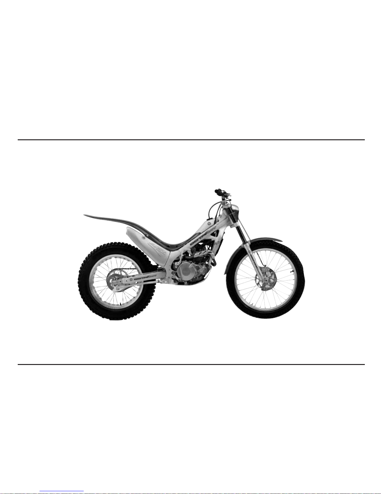
To The New Owner
By selecting a MONTESA COTA 4RT as your new
machine, you have placed yourself in a distinguished
family of owners and riders.
The COTA is a high performance trial motorcycle
utilizing the latest trial technology. This motorcycle is
intended for competition use by experienced riders only.
This new trialer was designed to be as competitive as
possible. But motorcycle trial is a physically demanding
sport that requires more than just a fine racing machine.
To do well, you must be in excellent physical condition
and be a skillful rider. For the best possible results, work
diligently on your physical conditioning and practice
frequently.
The purpose of this Manual is to help ensure that you
obtain the greatest possible satisfaction from your new
COTA trialer.
Importance Of Proper Preparation
Proper pre-competition preparation and regular service
is essential to rider safety and the reliability of the
motorcycle. Any error or oversight made by the
technician during preparation or servicing can easily
result in faulty operation, damage to the machine, or
injury to the rider.
Parts Availability
Orders for the parts tend to be concentrated during the
season, so you need to plan your parts orders carefully.
To prevent delays in shipment, place orders on regularly
replaced and fast-wearing parts well ahead of the season
(see page 3-2).
How To Use This Manual
The purpose of this Owner’s Manual is to help ensure
that you obtain the greatest possible satisfaction from
your new COTA trialer; satisfaction with the performance
of the motorcycle, and through success in competition.
If you plan to do any service on your COTA, section 3
describes standard maintenance and sections 4 through
6 contain in information on repair, disassembly,
assembly and special tools.
Follow the Maintenance Schedule recommendation
(page 3-1) to ensure that your COTA is always in peak
operating condition.

Memo
1. Operating Instructions
1-1
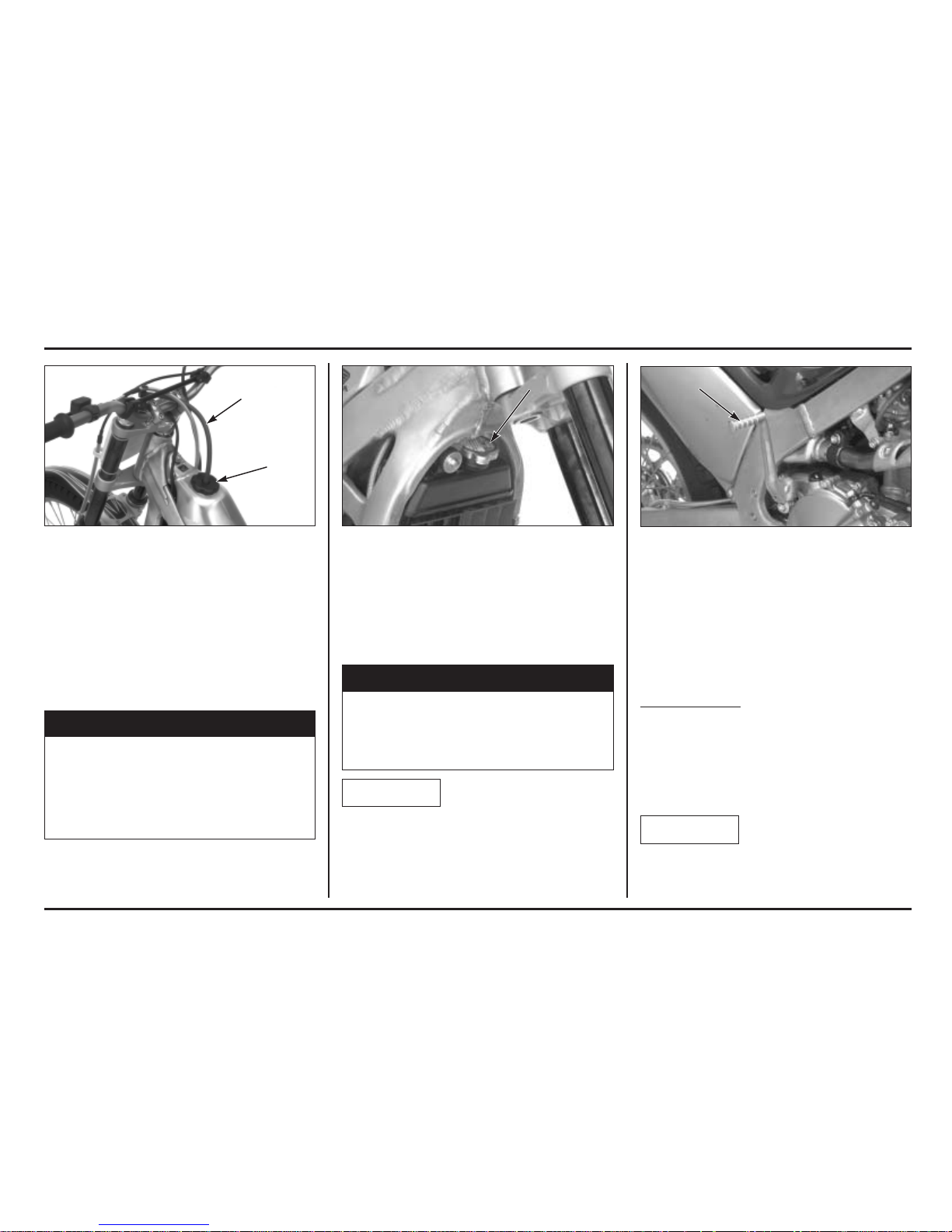
(1) BREATHER HOSE (2) FUEL TANK CAP (1) RADIATOR CAP
Fuel
Gasoline: Premium unleaded gasoline (commercially
available unleaded; pump octane number 91
or higher)
Fuel tank capacity: 2.0 liter (0.53 US gal, 0.44 Imp gal)
Disconnect the fuel tank breather hose clamp from the
clutch hose.
Turn the fuel tank cap counterclockwise, then remove the
cap.
Gasoline is highly flammable and is explosive.
You can be burned or seriously injured when
refueling.
• Stop engine and keep heat, sparks, and flame
away.
•Refuel only outdoors.
•Wipe up spills immediately.
Install the fuel tank cap by turning it clockwise.
Install the breather hose clamp onto the clutch hose.
Coolant
The engine of COTA is a water-cooled type. In order to
provide adequate cooling, it is essential that the radiator
be filled with coolant up the proper level (See pag. 3-9).
Coolant: 50/50 Mixture of Coolant and Distilled Water
Removing the radiator cap while the engine is hot
will allow the coolant to spray out, seriously scalding
you.
Always let the engine and radiator cool down before
removing the radiator cap.
When filling the coolant system, be sure to bleed air
completely. If not, the system cannot be sufficiently filled
and will cause overheating.
(1)
Basic Operation
Starting The Engine
Your COTA exhaust contains poisonous carbon
monoxide gas. High levels of carbon monoxide can
collect rapidly in enclosed areas such as a garage. Do not
run the engine with the garage door closed. Even with
the door open, run the engine only long enough to move
your COTA out of the garage.
Cold Engine Star
ting
1. Shift the transmission into neutral.
2. With the throttle fully closed, operate the kickstarter.
Starting from the top of the kickstarter stroke, kick
through to the bottom with a rapid, continuous
motion.
3. After the engine starts, run it for a few minutes,
“blipping” the throttle, until it warms up enough to
idle.
Do not start the engine with the transmission into gear
while squeezing the clutch lever, so the motorcycle will
move forward.
(1) KICKSTARTER PEDAL
(1)
NOTICE
NOTICE
!
WARNING
!
WARNING
(1)
(2)

Operating Instructions
1-2
(1) ENGINE STOP BUTTON
When you shift the transmission into gear, apply front
brake to prevent the motorcycle move forward.
Stopping The Engine
1. Shift the transmission into neutral.
2. Push the engine stop button until the engine stops
completely.
Break-In Procedure
New Motor
cycle
Following proper break-in procedure helps ensure that
the most important and expensive components on your
new motorcycle will provide maximum performance and
service life. (Also follow proper break-in procedure for a
newly rebuilt engine.)
When riding a new motorcycle, operate the motorcycle
for the first 20 minutes using not more than half throttle
and shifting gears so that the engine does not lug:
Reconditioned Motor
cycle
• After replacing the cylinder and crankshaft, operate
the motorcycle 20 minutes observing the same
cautions as for a new motorcycle.
•When the piston, piston ring, gears, etc. are replaced,
they must be broken in observing the first 30 minutes
using not more than half throttle and shifting gears so
that the engine does not lug:
(1)
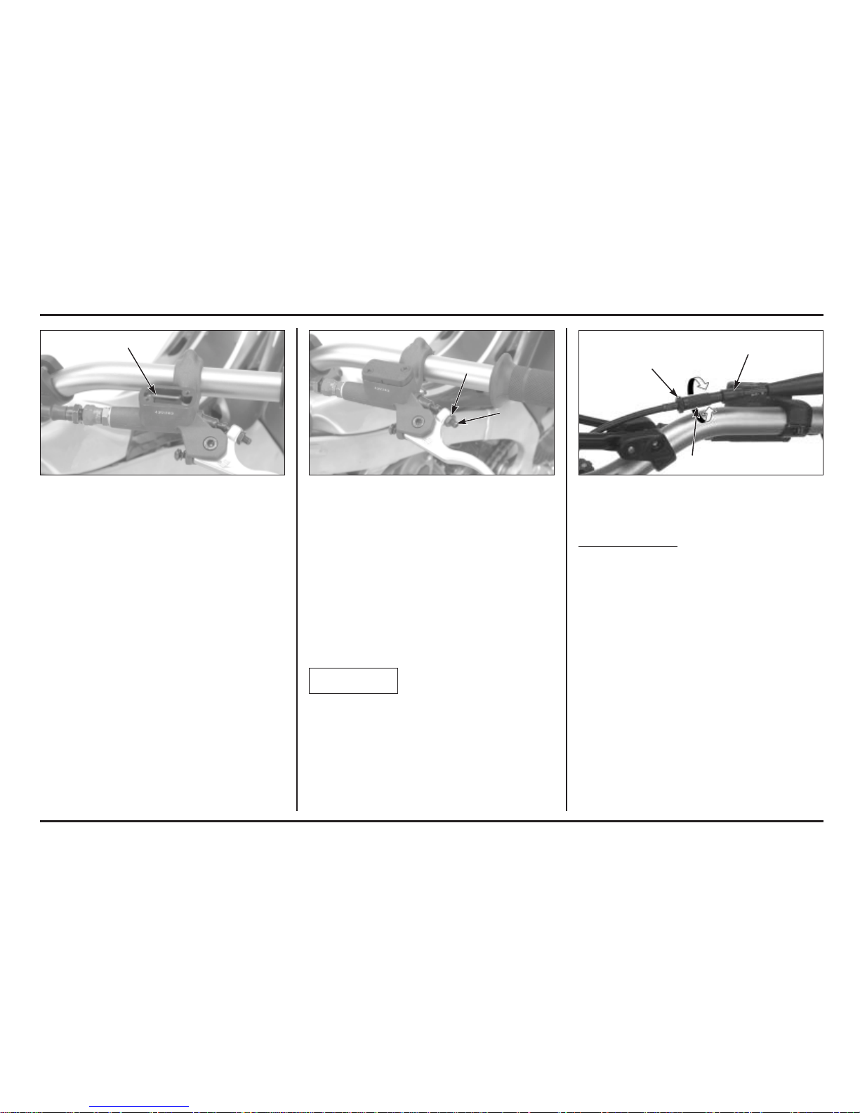
(1) UPPER LEVEL LINE (1) ADJUSTER (2) LOCK NUT (1) DUST COVER (2) LOCK NUT (3) ADJUSTER
(A) DECREASE (B) INCREASE
Controls
Clutch
Your COTA has a hydraulically actuated clutch. There are
no adjustments to perform but the clutch system must
be inspected periodically for fluid level and leakage.
If the control lever free play becomes excessive and the
motorcycle creeps or stalls when shifted into gear, or if
the clutch slips, causing acceleration to lag behind
engine speed, there is probably air in the clutch
hydraulic system and it must be bled out.
Clutch Lever
The clutch lever free play can be adjusted by turning the
adjuster.
Free play must be adjusted to provide 0.1 – 1.4 mm
(0.004 – 0.055 in) clearance between the end of the
adjuster and the clutch master cylinder piston.
To increase free play, turn the adjuster clockwise, then
tighten the lock nut securely.
If the clutch lever free play exceeds 30 mm (1.2 in) even
though the end of the adjuster and the clutch master
cylinder piston is adjusted to the minimum of 0.1 mm
(0.004 in), there is probably air in the clutch system and
it must be bled.
Do not adjust the end of the adjuster and the clutch
master cylinder piston below 0.1 mm (0.004 in).
Throttle Grip
Thr
ottle Grip Free Play
Standard throttle grip free play is approximately 3 mm
(0.12 in) of grip rotation.
Adjustment is made with the integral throttle cable
adjuster.
Slide the dust cover off from the integral cable adjuster.
Turning the adjuster in direction “A” will decrease free
play and turning it in direction “B” will increase free
play. Tighten the lock nut after adjustment.
Operate the throttle grip to ensure that it functions
smoothly and returns completely in all steering position.
Operating Instructions
1-3
(1)
(2)
(1)
(1)
(3)
(2)
(A)
(B)
NOTICE
Operating Instructions
1-4
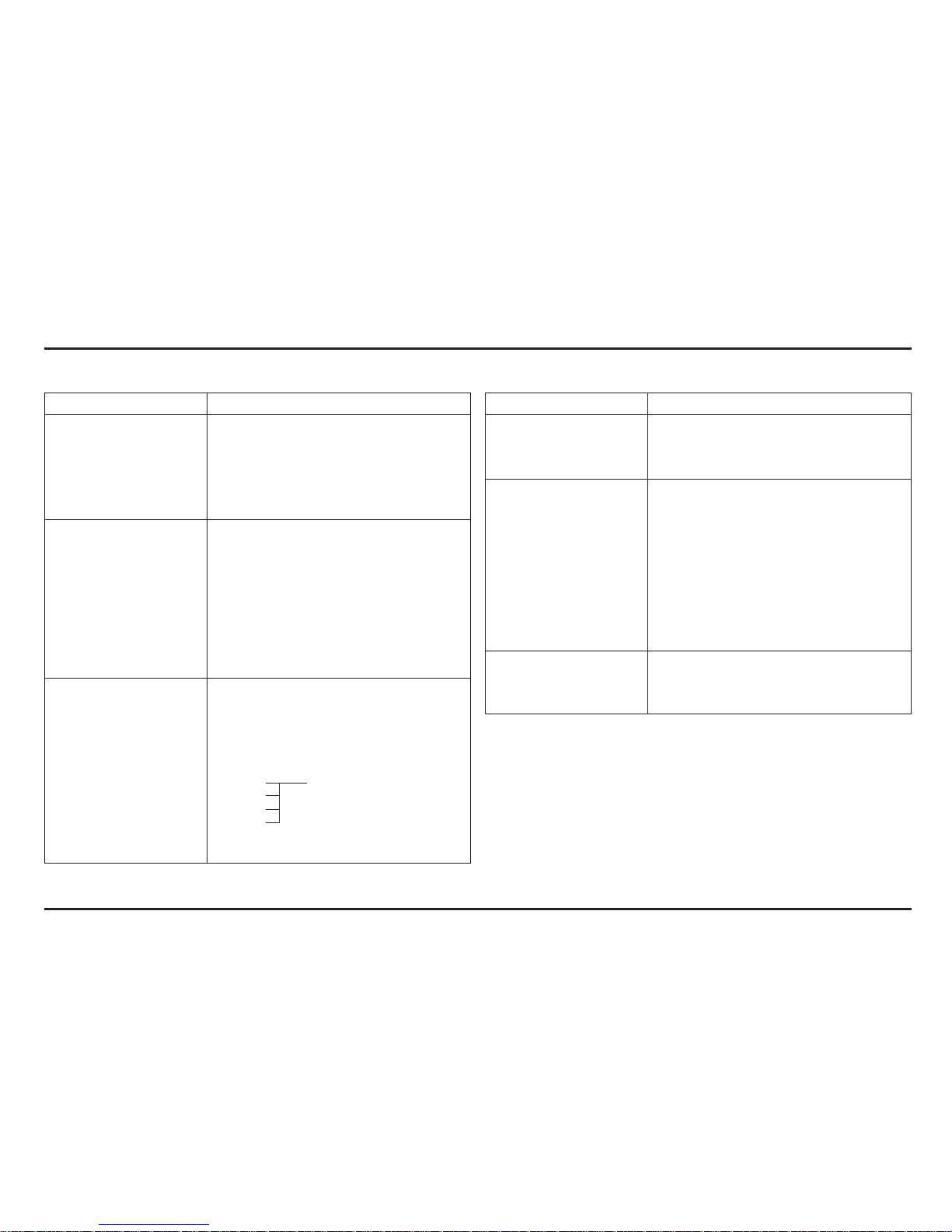
(1) LOCK NUT (2) ADJUSTING BOLT
(A) RAISE THE PEDAL HEIGHT
(B) LOWER THE PEDAL HEIGHT
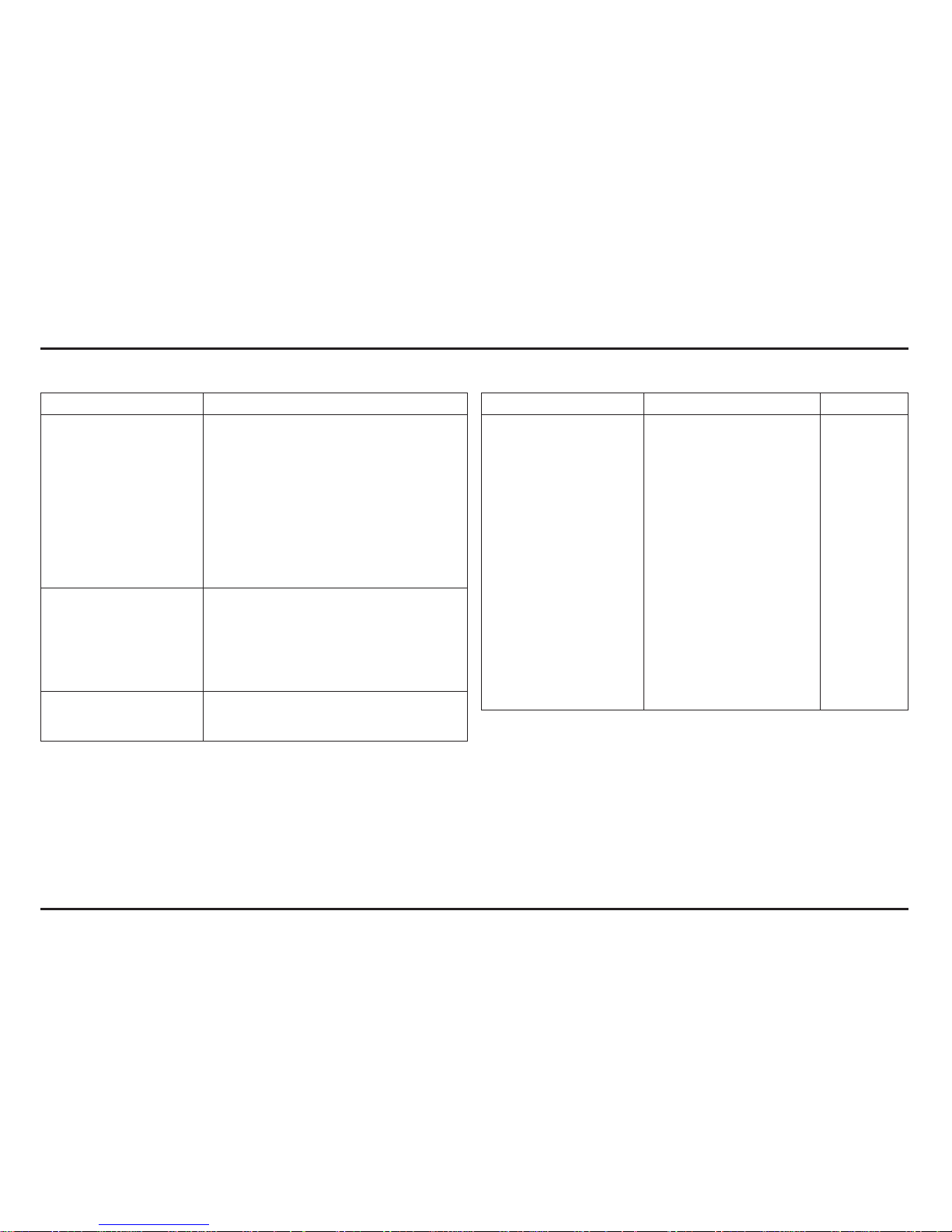
(1) HANDLEBAR
Brake Pedal Height
The brake pedal height can be adjusted to the rider’s
preference.
To adjust the rear brake pedal height:
1. Loosen the push rod lock nut and brake pedal
adjusting bolt lock nut. Then turn the both adjusting
bolts in direction “A” to raise the pedal, or in direction
“B” to lower it.
2. Tighten the lock nuts at the desired pedal height.
3. After adjustment, check the brake pedal free play at
the top of the pedal.
Make sure that the clearance between the front
adjusting bolt and frame is at least 1 mm (0.04 in).
Handlebar Position, Width And Shape
Position the handlebar so that gripping the bar and
operating the controls is comfortable while both seated
and standing, while riding straight ahead and turning.
Handlebar width can be trimmed with a hacksaw to
better your particular shoulder width and riding
preference. Think this though carefully and cut off just a
small amount at a time from both side equally. It is
obviously much easier to make the handlebar narrower
than it is to add material.
Chamfer the edges to remove burrs and other
irregularities or roughness after shaping.
An alternate handlebar shape. through varying rise or
rearward sweep dimensions, will provide further
adjustment to riding position and may better suit your
particular body size or riding style. Each of the
ergonomic dimensions of the motorcycle were
determined to suit the greatest possible number of riders
based on an average size rider.
(1)
(2)
(B)
(1)
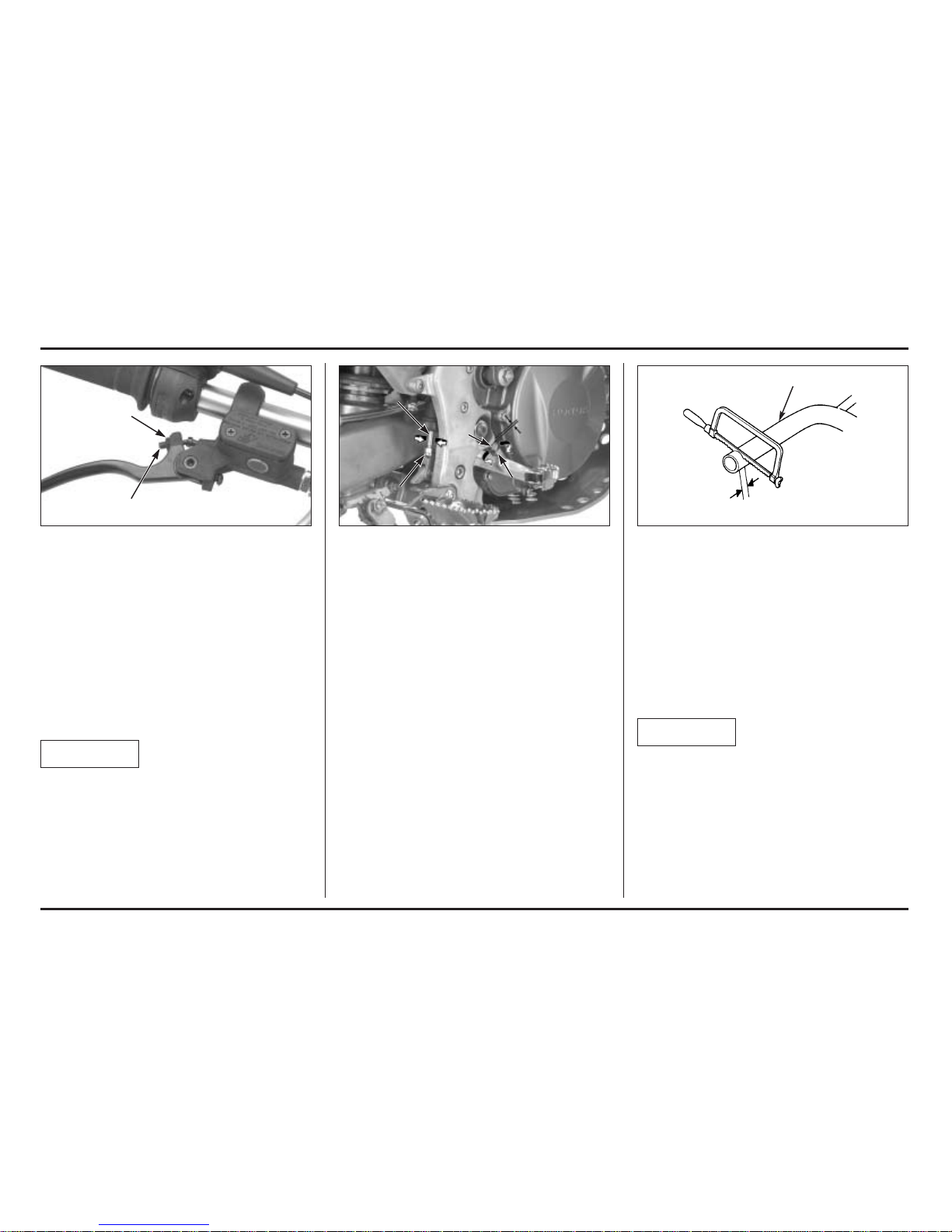
Front Brake Lever
The front brake lever free play can be adjusted by
turning the adjuster.
Free play must be adjusted to provide 0.1 – 1.4 mm
(0.004 – 0.055 in) clearance between the end of the
adjuster and the front brake master cylinder piston.
To increase free play, turn the adjuster clockwise, then
tighten the lock nut securely.
If the brake lever free play exceeds 30 mm (1.2 in) even
though the end of the adjuster and the front brake
master cylinder piston is adjusted to the minimum of 0.1
mm (0.004 in), there is probably air in the brake system
and it must be bled.
Do not adjust the end of the adjuster and the front brake
master cylinder piston below 0.1 mm (0.004 in).
(1) ADJUSTER (2) LOCK NUT
(1)
(2)
(A)
(B)
(A)
(2)
(1)
NOTICE
NOTICE
2. Service Data
2-1
Specifications
Item Specification
Dimensions
Overall length 2,016 mm (79.4 in)
Overall width 830 mm (32.7 in)
Overall height 1,130 mm (44.5 in)
Wheelbase 1,321 mm (52.0 in)
Seat height 650 mm (25.6 in)
Ground clearance 335 mm (13.2 in)
Frame
Type Aluminum twin tube
Front suspension Telescopic
Rear suspension Swingarm
Front tire MICHELIN TRIAL 2.75 – 21 TT
Rear tire MICHELIN TRIAL 4.00 R18 TL (tubeless)
Front brake, diameter Single disc, 185 mm
Rear brake, diameter Single disc, 150 mm
Fuel capacity 2.0 liter (0.53 US gal, 0.44 Imp. gal)
Caster angle 23˚ 00’
Trail length 63 mm (2.5 in)
Engine
Type Liquid cooled 4–stroke engine
Cylinder arrangement Single cylinder, 3.5˚ inclined from vertical
Bore and stroke 76.5 x 54.2 mm (3.01 x 2.13 in)
Displacement 249.1 cm
3
(15.2 cu-in)
Compression ratio 10.5 : 1
Valve timing
Intake valve opens 6˚ BTDC (at 1.0 mm lift)
Intake valve closes 27˚ ABDC
Exhaust valve opens 30˚ BBDC
Exhaust valve closes 1˚ ATDC
Lubrication system Forced pressure and wet sump
Starting system Primary kickstarter
Item Specification
Fuel System
Type PGM-FI
Identification number GQP0
Throttle bore 28 mm (1.1 in)
Drive Train
Clutch operating system Hydraulic operated
Clutch type Wet, multi-plate
Transmission 5 speed constant mesh
Primary reduction 3.167 (57/18T)
Gear ratio 1st 2.800 (42/15T)
2nd 2.385 (31/13T)
3rd 2.000 (30/15T)
4th 1.273 (28/22T)
5th 0.815 (22/27T)
Final reduction 4.100 (41/10T)
Gearshift pattern 1 – N – 2 – 3 – 4 – 5
Electrical
Alternator Triple phase output alternator
Ignition system PGM-IGN
Regulator type SCR shorted/triple phase, full wave rectification
Service Data
2-2
Service Data
Item Specification
Lubrication
Specified engine oil Honda Ultra S9 4-stroke motorcycle oil or
Repsol 4T oil
SAE 10W-40
Engine oil capacity
after draining 0.41 liter (0.43 US qt, 0.36 Imp qt)
after oil filter change 0.44 liter (0.46 US qt, 0.39 Imp qt)
after disassembly 0.60 liter (0.63 US qt, 0.53 Imp qt)
Specified transmission oil ELF HTX740
Transmission oil capacity
after draining 0.54 liter (0.57 US qt, 0.48 Imp qt)
after disassembly 0.57 liter (0.60 US qt, 0.50 Imp qt)
Fuel System
Throttle body identification No.
GQP0A
Throttle grip free play 3 mm (0.1 in)
Engine idle speed 1,800 ± 100 min
-1
(rpm)
Fuel pressure 260 kPa (2.65 kgf/cm
2
, 38 psi) at idle
Fuel pump flow at 12 V 17 cm
3
(0.6 US oz, 0.6 Imp oz) minimum/10 seconds
Injector resistance 11.1 – 12.3 Ω (20˚C/68˚F)
Cooling System
Recommended coolant 50/50 mixture coolant and distilled water
Radiator cap relief pressure 117 kPa (1.2 kgf/cm
2
, 17 psi)
Item Standard Service Limit
Cylinder Head/Valves
Cylinder compression 460 kPa (4.7 kgf/cm
2
, 67 psi) at
–
800 min-1(rpm)
Cylinder head warpage
–
0.05 (0.002)
Valve clearance IN 0.12 ± 0.03 (0.005 ± 0.001)
–
EX 0.30 ± 0.03 (0.012 ± 0.001)
–
Valve stem O.D. IN 4.475 – 4.490 (0.1762 – 0.1768) 4.470 (0.1760)
EX 4.465 – 4.480 (0.1758 – 0.1764) 4.460 (0.1756)
Valve guide I.D. IN/EX 4.500 – 4.512 (0.1772 – 0.1776) 4.552 (0.1792)
Valve stem-to-guide clearance
IN 0.010 – 0.037 (0.0004 – 0.0015)
–
EX 0.020 – 0.047 (0.0008 – 0.0019)
–
Valve guide projection IN 8.0 – 8.3 (0.31 – 0.33)
–
above cylinder head EX 8.2 – 8.5 (0.32 – 0.33)
–
Valve spring free length
Inner 25.41 (1.000) 24.9 (0.98)
Outer 28.32 (1.115) 27.6 (1.09)
Rocker arm I.D. 10.000 – 10.015 (0.3937 – 0.3943) 10.051 (0.3957)
Rocker arm shaft O.D. 9.972 – 9.987 (0.3926 – 0.3932) 9.925 (0.3907)
Rocker arm-to-shaft clearance 0.013 – 0.043 (0.0005 – 0.0017) 0.11 (0.04)
Cam lobe height IN 32.011 – 33.051 (1.2603 – 1.3012) 31.871 (1.2548)
EX 32.855 – 32.935 (1.2935 – 1.2967) 32.748 (1.2893)
Unit: mm (in)
Service Data
2-3
Item Standard Service Limit
Crankshaft/Transmission
Crankshaft runout Right
–
0.03 (0.001)
Left
–
0.05 (0.002)
Connecting rod big end
Side clearance 0.30 – 0.75 (0.012 – 0.030) 0.8 (0.03)
Radial clearance 0.06 – 0.18 (0.002 – 0.007) 0.05 (0.002)
Transmission gear I.D. M4 23.020 – 23.041 (0.9063 – 0.9071) 23.07 (0.908)
M5 23.020 – 23.041 (0.9063 – 0.9071) 23.07 (0.908)
C1 20.020 – 20.041 (0.7882 – 0.7890) 20.06 (0.790)
C2 25.020 – 25.041 (0.9850 – 0.9859) 25.06 (0.987)
C3 25.020 – 25.041 (0.9850 – 0.9859) 25.06 (0.987)
Gear bushing I.D. M5 20.000 – 20.021 (0.7866 – 0.7882) 20.05 (0.789)
C1 17.000 – 17.018 (0.6693 – 0.6700) 17.04 (0.671)
C2 22.000 – 22.021 (0.8661 – 0.8670) 22.04 (0.868)
C3 22.000 – 22.021 (0.8661 – 0.8670) 22.04 (0.868)
O.D. M4 22.979 – 23.000 (0.9047 – 0.9055) 22.96 (0.904)
M5 22.979 – 23.000 (0.9047 – 0.9055) 22.96 (0.904)
C1 19.979 – 20.000 (0.7866 – 0.7874) 19.95 (0.785)
C2 24.979 – 25.000 (0.9834 – 0.9843) 24.95 (0.982)
C3 24.979 – 25.000 (0.9834 – 0.9843) 24.95 (0.982)
Countershaft O.D.
at C1 bushing 16.983 – 16.994 (0.6686 – 0.6691) 16.97 (0.668)
at C2/C3 bushing 21.959 – 21.980 (0.8645 – 0.8654) 21.94 (0.864)
at kickstarter idle gear 16.983 – 16.994 (0.6686 – 0.6691) 16.97 (0.668)
Shift fork I.D. C 11.003 – 11.024 (0.4332 – 0.4330) 11.04 (0.435)
R, L 12.035 – 12.056 (0.4738 – 0.4746) 12.07 (0.475)
Shift fork claw thickness C 4.93 – 5.00 (0.194 – 0.197) 4.8 (0.19)
R, L 4.93 – 5.00 (0.194 – 0.197) 4.8 (0.19)
Shift fork shaft O.D. C 10.983 – 10.994 (0.4324 – 0.4328) 10.97 (0.432)
R, L 11.966 – 11.984 (0.4711 – 0.4718) 11.95 (0.470)
Oil pump
Tip clearance
–
0.20 (0.008)
Body clearance 0.15 – 0.20 (0.006 – 0.008)
–
Side clearance 0.05 – 0.12 (0.002 – 0.004)
–
Unit: mm (in)
Item Standard Service Limit
Cylinder/Piston
Cylinder I.D. 76.500 – 76.515 (3.0118 – 3.0124) 76.54 (3.013)
Taper
–
0.05 (0.002)
Out-of- round
–
0.05 (0.002)
Warpage
–
0.05 (0.002)
Piston O.D. 76.470 – 76.480 (3.0106 – 3.0110) 76.39 (3.007)
Measurement point 5 (0.2) from bottom of skirt
–
Pin bore I.D. 16.002 – 16.008 (0.6300 – 0.6302) 16.03 (0.631)
Piston pin O.D. 15.994 – 16.000 (0.6297 – 0.6299) 15.98 (0.629)
Piston ring
End gap Top 0.20 – 0.30 (0.008 – 0.012) 0.44 (0.017)
Second 0.35 – 0.50 (0.014 – 0.020) 0.64 (0.025)
Oil (side rail) 0.20 – 0.70 (0.008 – 0.028) 0.90 (0.035)
Ring-to-groove clearance
To p 0.065 – 0.100 (0.0026 – 0.0039) 0.115 (0.0045)
Second 0.015 – 0.050 (0.0006 – 0.0020) 0.065 (0.0026)
Cylinder-to-piston clearance 0.020 – 0.045 (0.0008 – 0.0018) 0.18 (0.007)
Piston-to-piston pin clearance 0.002 – 0.014 (0.0001 – 0.0006) 0.04 (0.002)
Connecting rod small end I.D. 16.016 – 16.034 (0.6305 – 0.6313) 16.04 (0.631)
Clutch/Gearshift Linkage
Recommended clutch fluid DOT 4 brake fluid
–
Clutch spring free length 27.6 (1.09) 26.8 (1.06)
Clutch disc thickness 3.22 – 3.38 (0.127 – 0.133) 3.15 (0.124)
Clutch plate warpage
–
0.10 (0.004)
Clutch slave cylinder I.D. 27.000 – 27.021 (1.0630 – 1.0638)
–
Clutch slave piston O.D. 26.940 – 26.960 (1.0606 – 1.0614)
–
Kickstarter Spindle O.D. 16.466 – 16.484 (0.6483 – 0.6490) 16.46 (0.648)
Pinion gear I.D. 16.516 – 16.534 (0.6502 – 0.6509) 16.55 (0.652)
Idle gear I.D. 17.016 – 17.034 (0.6699 – 0.6706) 17.06 (0.672)
Countershaft O.D.
at kickstarter idle gear 16.983 – 16.994 (0.6686 – 0.6691) 16.97 (0.668)
Unit: mm (in)
Service Data
2-4
Item Standard Service Limit
Rear Suspension
Shock absorber spring pre-load
126.5 (4.9)
–
Spring free length 133 (5.2) 130.3 (5.13)
Nitrogen gas pressure 1.27 MPa (13 kgf/cm
2
)
–
Damper rod compressed
force at 10 mm compressed 196 – 232 N (19.9 – 23.6 kgf)
–
Tension adjuster setting 10 clicks from full hard
–
Brakes
Recommended brake fluid DOT 4 brake fluid
–
Front Brake disc thickness 3.5 (0.14) 3.0 (0.12)
Brake disc runout
–
0.15 (0.006)
Rear Brake disc thickness 2.5 (0.10) 2.0 (0.08)
Brake disc runout
–
0.15 (0.006)
Electrical
Spark plug Standard: NGK: CR6EH-9
–
Optional NGK: CR5EH-9
–
Spark plug gap 0.80 – 0.90 (0.031 – 0.035)
–
Ignition coil resistance
Primary 2.6 – 3.2 Ω (20˚C/68˚F)
–
Secondary with plug cap 17.3 – 22.8 kΩ (20˚C/68˚F)
–
Secondary without plug cap
13.5 – 16.5 kΩ (20˚C/68˚F)
–
Ignition pulse generator
Resistance 85 – 115 Ω (20˚C/68˚F)
–
Alternator
Regulated voltage 13.5 – 14.5 V/1,800 min
-1
(rpm)
–
Charging coil resistance 0.7 – 1.0 Ω (20˚C/68˚F)
–
ECT sensor resistance 2.3 – 2.6 kΩ (20˚C/68˚F)
–
Bulbs
Headlight 12V – 35/35 W
–
Position light 12V – 4 W
–
Brake/tail light 12V – 21/5 W
–
Turn signal light 12V – 10 W X 4
–
Unit: mm (in)
Item Standard Service Limit
Wheels/Tires
Axle runout
–
0.20 (0.008)
Tire air pressure Front 39 – 44 kPa (0.40 – 0.45 kgf/cm
2
,
5.6 – 6.5 psi)
–
Rear 29 – 34 kPa (0.30 – 0.35 kgf/cm2,
4.3 – 5.0 psi)
–
Wheel rim runout Radial
–
2.0 (0.08)
Axial
–
2.0 (0.08)
Drive chain slack 25 – 35 (1.0 – 1.4)
–
Drive chain slider thickness
–
2.0 (0.08) from
upper surface
Front Suspension
Left fork spring free length 384.8 (15.14) 377.1 (14.85)
Fork tube runout
–
0.20 (0.008)
Recommended fork fluid Showa SS05
Pre-load adjuster setting 2 turns out from full soft
–
Damping adjuster setting Compression adjuster:
13 clicks from full hard
–
Tension adjuster:
12 clicks from full hard
–
Fork oil level Right 38 (1.5)
–
Left 87 (3.4)
–
Fork oil capacity Right 405 cm3(13.7 US oz, 14.3 Imp oz)
–
Left 410 cm3(13.9 US oz, 14.4 Imp oz)
–
Unit: mm (in)
Service Data
2-5
Torque Values
Standard
Tor que
Item
N•m (kgf•m, lbf•ft)
5 mm bolt and nut 5 (0.52, 3.5)
6 mm bolt and nut 10 (1.0, 7)
8 mm bolt and nut 22 (2.2, 16)
10 mm bolt and nut 33 (3.4, 25)
12 mm bolt and nut 53 (5.4, 40)
5 mm screw 4 (0.42, 3)
6 mm screw and flange bolt (SH type) 9 (0.9, 7)
6 mm flange bolt and nut 12 (1.2, 9)
8 mm flange bolt and nut 26 (2.7, 20)
10 mm flange bolt and nut 38 (3.9, 29)
Engine
Threads Torque
Item Q’ty Remarks
Dia. (mm) N•m (kgf•m, lbf•ft)
Transmission oil drain bolt 1 8 22 (2.2, 16) Note 1
Engine oil drain bolt 1 8 22 (2.2, 16) Note 1
Right crankcase cover joint pipe 1 18 18 (1.8, 13) Note 2
Timing hole cap 1 14 7 (0.7, 5.1) Note 3
Bearing set plate socket bolt 4 6 9.8 (1.0, 7) Note 4
Bearing set plate screw 2 6 12 (1.2, 9) Note 4
Bearing set plate flat screw 2 6 9.8 (1.0, 7) Note 4
Cylinder head sealing bolt 1 12 32 (3.3, 24) Note 4
Cylinder head mounting nut 2 9 39 (4.0, 29) Note 1
Cylinder head joint pipe 1 18 18 (1.8, 13) Note 2
Vacuum port joint 1 5 2.5 (0.25, 1.8)
Primary drive gear special bolt 1 12 108 (11.0, 80) Note 1
Flywheel nut 1 18 167 (17.0, 123) Note 1
Cam chain tensioner bolt 1 6 12 (1.2, 9) Note 4
Valve clearance adjusting nut 4 6 14 (1.4, 10) Note 1
Injector holder socket bolt 2 6 9.8 (1.0, 7)
Fuel hose banjo bolt (holder side) 1 18 27 (2.8, 20)
Water pump impeller 1 7 12 (1.2, 9)
Clutch oil bleeder screw 1 8 6 (0.6, 4.3)
Clutch spring bolt 6 6 12 (1.2, 9)
Clutch center lock nut 1 18 69 (7.0, 51) Note 1
Drive sprocket UBS bolt 1 8 31 (3.2, 23)
Shift drum center special bolt 1 8 22 (2.2, 16) Note 4
Shift drum stopper arm bolt 1 6 12 (1.2, 9)
Shift return spring pin 1 8 22 (2.2, 16)
Ignition pulse generator bolt 2 5 5.4 (0.55, 4.0) Note 4
Stator mounting bolt 3 5 5.4 (0.55, 4.0) Note 4
Spark plug 1 10 16 (1.6, 12) Note 2
Notes: 1. Apply clean engine oil to the threads and seating surface.
2. Apply sealant to the threads.
3. Apply grease to the threads.
4. Apply a locking agent to the threads.
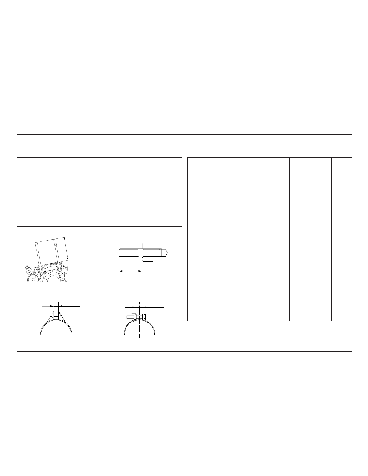
Cylinder stud bolt: Exhaust pipe stud bolt:
101.5 ± 1 mm
17 ± 0.5 mm
Insulator band (cylinder head side): Insulator band (throttle body side):
7 ± 1 mm
7 ± 1 mm

Service Data
2-6
Frame
Threads Torque
Item Q’ty Remarks
Dia. (mm) N•m (kgf•m, lbf•ft)
Handlebar holder bolt 4 8 22 (2.2, 16)
Front axle 1 17 69 (7.0, 51) Note 1
Rear axle 1 17 69 (7.0, 51) Note 1
Final driven sprocket nut 4 8 29 (3.0, 22)
Shock absorber:
Upper mounting bolt/nut 1 10 39 (4.0, 29)
Lower mounting bolt/nut 1 10 39 (4.0, 29)
Fork top pinch bolt 2 8 20 (2.0, 14) Note 1
Fork bottom pinch bolt 4 8 20 (2.0, 14) Note 1
Swingarm pivot nut 1 14 69 (7.0, 51) Note 1
Front brake disc mounting bolt 4 6 18 (1.8, 13) Note 2
Rear brake disc mounting bolt 4 6 17 (1.7, 12) Note 2
Side stand pivot nut 1 10 23 (2.3, 17)
Side stand bracket mounting bolt
28 26 (2.7, 20) Note 2
Exhaust pipe flange bolt 1 6 12 (1.2, 9)
Engine hanger:
Upper hanger bolt/nut 1 8 24 (2.4, 17)
Front hanger bolt 1 10 49 (5.0, 36) Note 1
Down tube mounting bolt 4 8 25 (2.6, 19) Note 1
Front axle holder bolt 2 6 23 (2.3, 17) Note 1
Skid plate:
Front mounting bolt 2 8 26 (2.7, 20)
Throttle housing bolt 2 5 4.2 (0.43, 3.1)
Clutch lever holder bolt 2 5 3.2 (0.33, 2.4)
Front brake master cylinder
holder bolt 2 6 3.2 (0.33, 2.4)
Front brake caliper mounting bolt
28 26 (2,7, 20) Note 2
Brake hose:
Front master cylinder 1 10 27 (2.8, 20)
Front caliper 1 10 27 (2.8, 20)
Rear master cylinder 1 10 27 (2.8, 20)
Rear brake caliper 1 10 27 (2.8, 20)
Brake pedal pivot bolt 1 8 29 (3.0, 22)
Steering head top thread 1 26 5 (0.5, 3.6) Note 1
Threads Torque
Item Q’ty Remarks
Dia. (mm) N•m (kgf•m, lbf•ft)
Steering stem bolt 1 20 88 (9.0, 65) Note 1
Clutch hose (master cylinder) 1 10 20 (2.0, 14)
Rear master cylinder mounting
bolt 2 6 8 (0.8, 5.8)
ECT sensor 1 12 15 (1.5, 11)
Fuel hose banjo bolt
Fuel pump side: 1 12 22 (2.2, 16)
Fuel pump mounting bolt 6 5 7 (0.7, 5.1)
Front spoke nipple 32 BC 3.5 3.2 (0.33, 2.4)
Rear spoke nipple 32 4 2.5 (0.25, 1.8)
Shock absorber spring lock nut 1 50 49 (5.0, 36)
Shock arm bolt/nut 1 10 39 (4.0, 29)
Shock link bolt/nut 2 10 39 (4.0, 29)
Clutch oil bleeder bolt 1 10 23 (2.3, 17)
Rim lock nut 1 8 13 (1.3, 9)
Fork cap 2 36 23 (2.3, 17)
Fork cap bolt-to-adjuster case 1 22 34 (3.5. 25)
Fork adjuster case lock nut 1 10 20 (2.0, 14)
Right fork center bolt 1 14 34 (3.5. 25) Note 2
Left fork center bolt 1 15 34 (3.5. 25) Note 2
Notes: 1. Apply grease to the sliding surface.
2. Apply a locking agent to the threads.

Service Data
2-7
Tools
Special Common
Description Tool number Applicability
Bearing remover, 12 mm 07936–1660101 Water pump bearing
– Remover shaft 07936–1660120
– Remover weight 07741–0010201
Water seal driver 07945–KA30000 Water seal
Attachment, 28 x 30 mm 07946–1870100 Water pump bearing
Clutch center holder 07JMB–MN50301 Clutch center lock nut
Fork seal driver set 07947–4630100 Fork oil seal
Fork damper holder 89515–NN3–821 Right fork socket bolt
Fork damper holder 07930–KA50100 Left fork socket bolt
Ball race remover 07948–4630100 Stem bearing race
Steering stem driver 07946–4300000 Stem lower bearing
Bearing driver 07946–KA50000 Swingarm pivot bearing
Bearing remover 07946–MJ00100 Shock link needle bearing
Swingarm link bearing
Spherical bearing driver 07HMF–KS60100 Shock absorber bearing
Snap ring pliers 07914–3230001 Master cylinder snap ring
* Flywheel holder 89020–NN4–003 Flywheel
* Flywheel puller 89010–NN4–003 Flywheel
Compressor attachment 07959–MB10000 Shock absorber spring
Description Tool number Applicability
Spoke nipple wrench 07701–0020200 Front spoke nipple
Gear holder 07724–0010100 Primary drive gear bolt
Bearing remover head 07746–0050600 Wheel bearing
Bearing remover shaft 07746–0050100 Wheel bearing
Driver 07749–0010000 Bearing removal/installation
Attachment, 24 x 26 mm 07746–0010700 Swingarm pivot bearing
Attachment, 32 x 35 mm 07746–0010100 Right countershaft bearing
Left mainshaft bearing
Attachment, 37 x 40 mm 07746–0010200 Left shift drum bearing
Attachment, 42 x 47 mm 07746–0010300 Right mainshaft bearing
Left countershaft bearing
Right shift drum bearing
Wheel bearing
Ball race
Attachment, 52 x 55 mm 07746–0010400 Crankshaft oil seal
Attachment, 62 x 68 mm 07746–0010500 Left crankshaft bearing
Attachment, 72 x 75 mm 07746–0010600 Right crankshaft bearing
Pilot, 12 mm 07746–0040200 Water pump bearing
Pilot, 17 mm 07746–0040400 Right countershaft bearing
Left mainshaft bearing
Pilot, 20 mm 07746–0040500 Left countershaft bearing
Wheel bearing
Swingarm pivot bearing
Pilot, 22 mm 07746–0041000 Right mainshaft bearing
Pilot, 25 mm 07746–0040600 Right shift drum bearing
Pilot, 30 mm 07746–0040700 Right crankshaft bearing
Pin spanner 07702–0020001 Shock spring adjuster
(2 required)
Shock absorber compressor 07GME–0010000 Shock absorber spring
* Newly designed tool for this model.
Service Data
2-8
Lubrication & Seal Points
Engine
Item Material Remarks
Crankcase sealing bolt threads and ELF HTX740
seating surface
Cylinder bore inner surface
Cylinder head nut threads and
seating surface
Piston pin bore and outer surface
Piston pin outer surface
Piston ring surface
Crankshaft oil seal lips
Decompressor weight sliding
surface
Valve adjusting nut threads
Oil pump rotor sliding surface
Clutch outer sliding surface
Clutch friction disc surface
Clutch center nut threads and
seating surface
Clutch lifter piece needle bearing
area
Primary drive gear bolt threads and
seating surface
Shift drum grooves
Gearshift spindle serration
Flywheel nut threads and seating
surface
Each bearing
Each O-ring
Crankcase inside (transmission oil) 600 cm
3
Crankcase inside (engine oil) Honda Ultra S9 4-stroke 600 cm
3
engine oil or
Repsol 4T oil
10W-40-MB
Item Material Remarks
Connecting rod small end I.D. Molybdenum oil solution
Connecting rod big end (A 50/50 mixture of
Camshaft outer surface molybdenum disulfide
Rocker arm I.D. grease and engine oil
Valve stem sliding surface
Valve stem end sliding surface
Clutch outer collar sliding surface
Mainshaft spline and gear sliding
surface
Countershaft spline and gear
sliding surface
Shift fork I.D. and gear contact area
Shift fork shaft surface
Kickstarter spindle spline area and
gear sliding surface
Each gear
Right crankshaft bearing set plate Locking agent 6.5 ± 1 mm
bolt threads
Right mainshaft bearing/shift drum
bearing set plate bolt threads
Left coutershaft bearing set plate 3.5 ± 1 mm
bolt threads
Left crankcase sealing bolt threads
Cylinder mounting bolt threads
Cylinder head sealing bolt threads 6.5 ± 1 mm
Cam chain tensioner bolt threads 6.5 ± 1 mm
Shift drum center bolt threads
Ignition pulse generator bolt
threads
Stator mounting bolt threads
Item Material Remarks
Clutch slave cylinder piston/O-ring Silicone grease
Left crankcase cover cap threads Lithium based multiEach oil seal lips purpose grease
Water seal lips
Right crankcase cover water hose Sealant
joint threads
Cylinder head water hose joint
threads
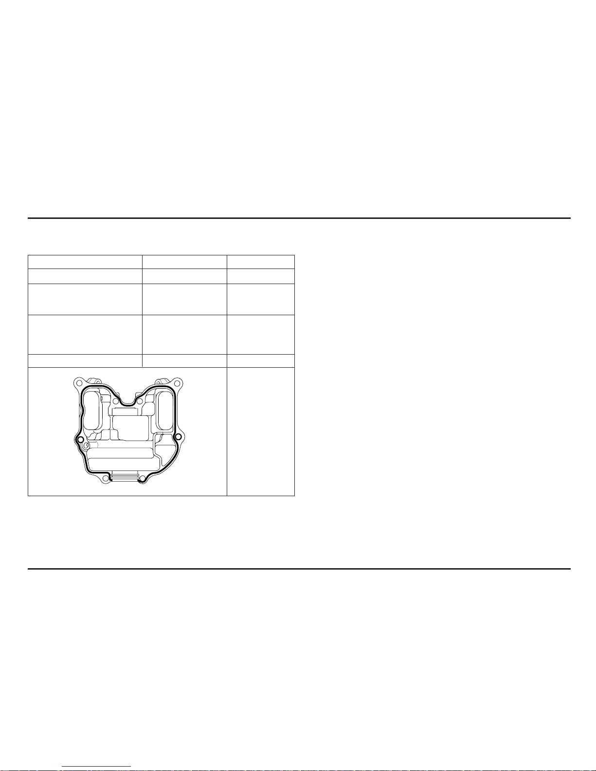
Cylinder head cover mating surface Three Bond 1215B
Service Data
2-9
Service Data
2-10
Frame
Item Material Remarks
Steering head bearing race and Multi-purpose grease
bearings
Steering head dust seal lips
Swingarm pivot needle bearing
Swingarm pivot dust seal lips
Shock link/shock arm needle
bearings
Shock link/shock arm dust seal lips
Kickstarter arm joint sliding
Brake lever pivot sliding surface
Side stand pivot sliding surface
Brake pedal pivot sliding surface
Chain tensioner roller bearings
Clutch lever pivot sliding surface
Wheel bearing spinning area
Wheel axle threads
Step joint pin surface
Throttle pipe sliding surface and 4-stroke engine oil
throttle wire drum
Throttle housing screw threads Molybdenum disulfide
grease
Brake hydraulic system inside DOT 4 brake fluid
Clutch hydraulic system inside
Air cleaner element Engine oil
Throttle cable sliding surface Cable lubricant
Handlebar grip Honda bond A or
equivalent
Item Material Remarks
Drive chain adjuster stopper screw Locking agent
threads
Side stand bracket bolt threads
Steering stopper bolt threads
Drive chain slider mounting screw
threads
Rear brake hose clamp screw
threads
Cooling fan nut threads

Service Data
2-11
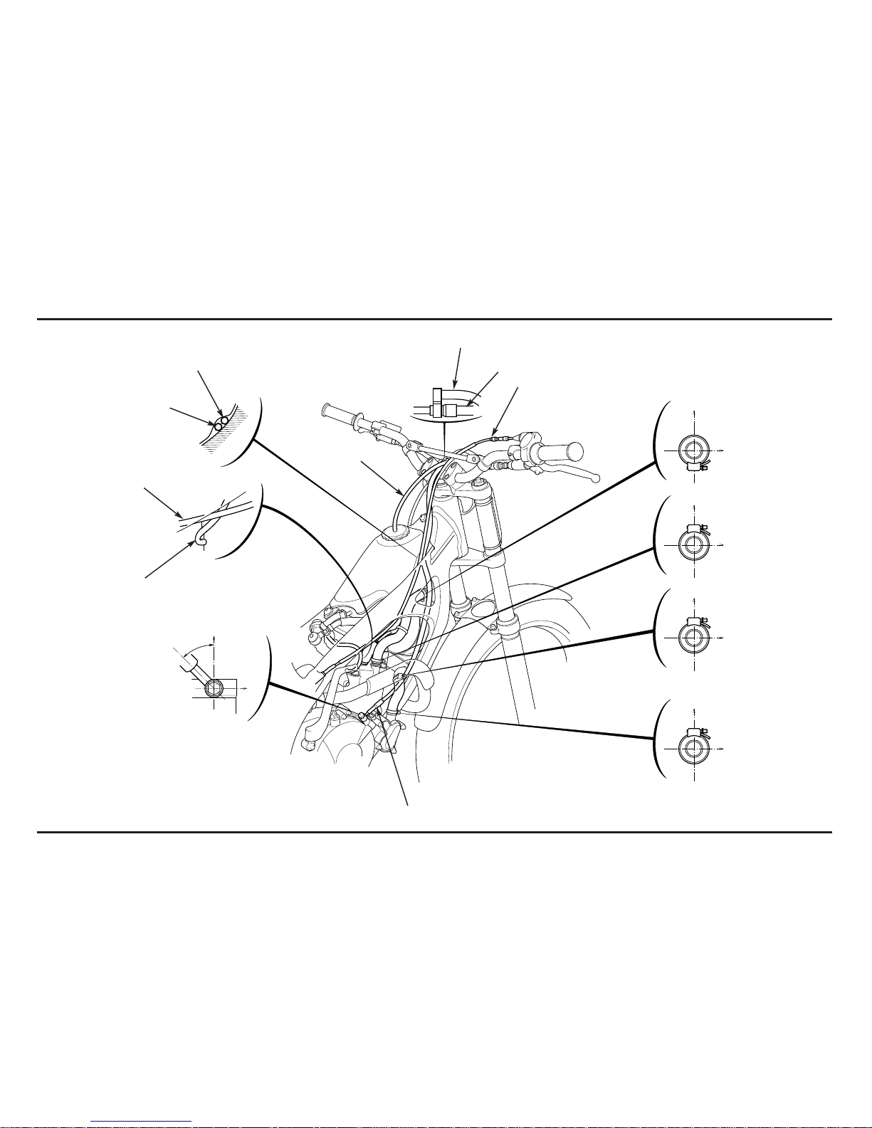
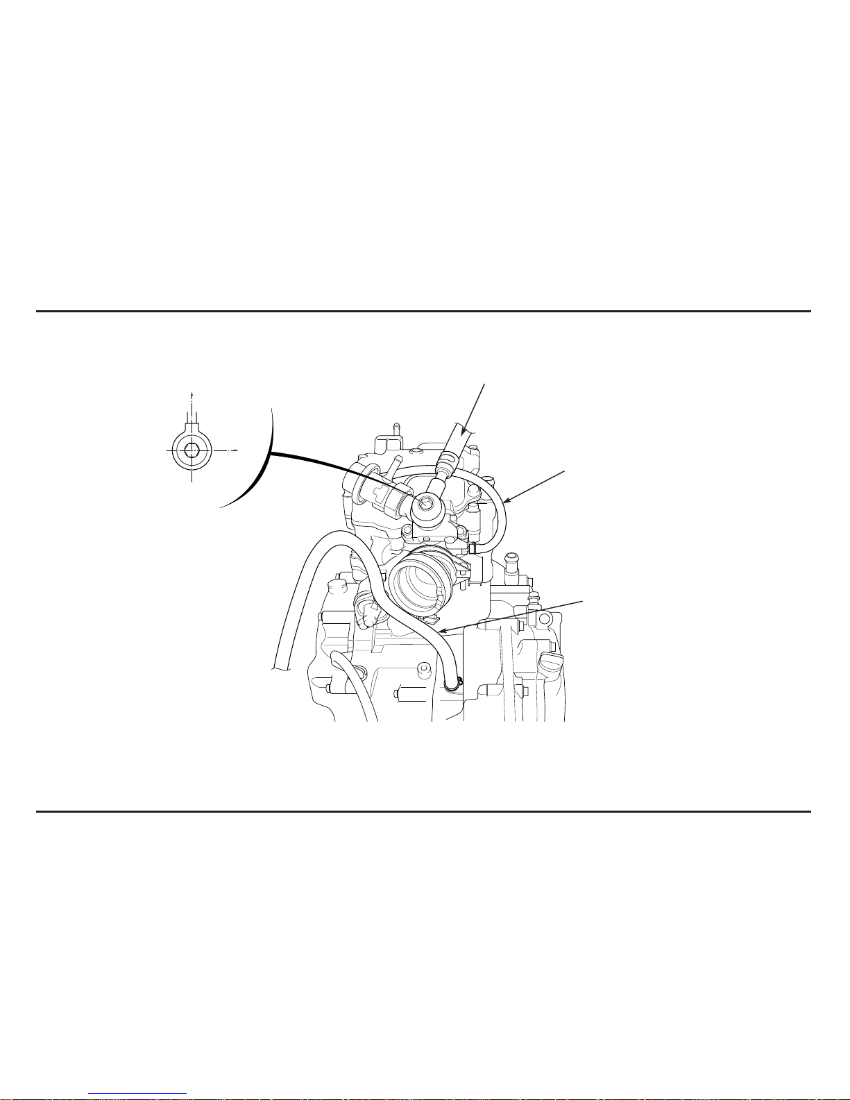
Cable & Harness Routing
(1) FRONT BRAKE HOSE
(2) THROTTLE CABLE
(3) CLUTCH HOSE
(4) ENGINE STOP SWITCH CONNECTOR
(2)
(1)
(3)
(4)
20 – 30˚
Front
Front
Front
Service Data
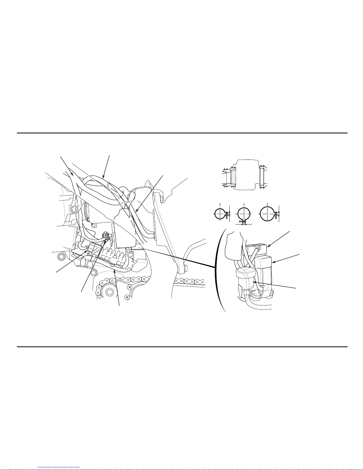
2-12
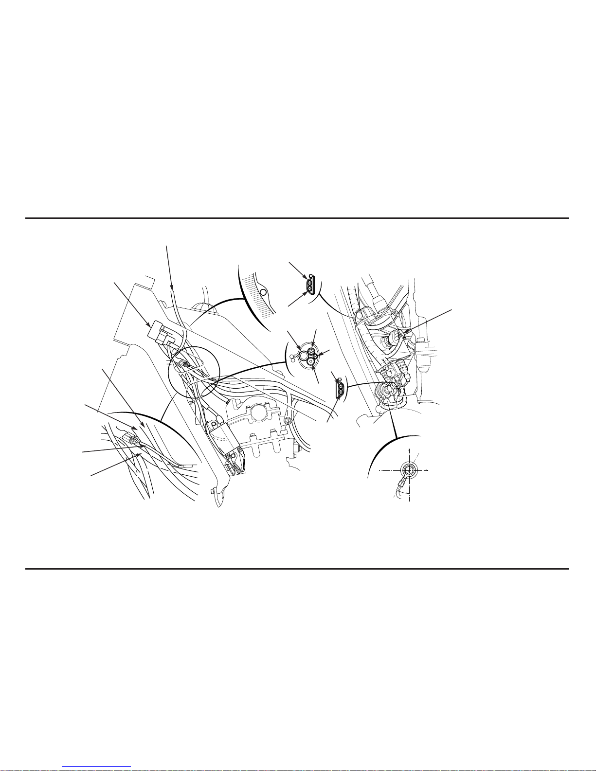
(1) MAIN WIRE HARNESS
(2) FUEL PUMP WIRE
(3) CRANKCASE BREATHER HOSE
(4) CRANKCASE BREATHER JOINT HOSE
(5) STRAGE TANK
(6) ENGINE STOP SWITCH WIRE
(7) FAN MOTOR WIRE
(8) RADIATOR OVERFLOW HOSE
(9) SPARK PLUG WIRE
(5)
(8)
(7)
(12)
(10)
(2)
(1)
(3)
(4)
Upper
Right
20 – 30˚
(6)
(7)
(9)
(1)
(10)
(10) WIRE HARNESS (TO IGNITION COIL)
(11) WIRE HARNESS (TO GROUND)
(12) ECT SENSOR
(11)
Service Data
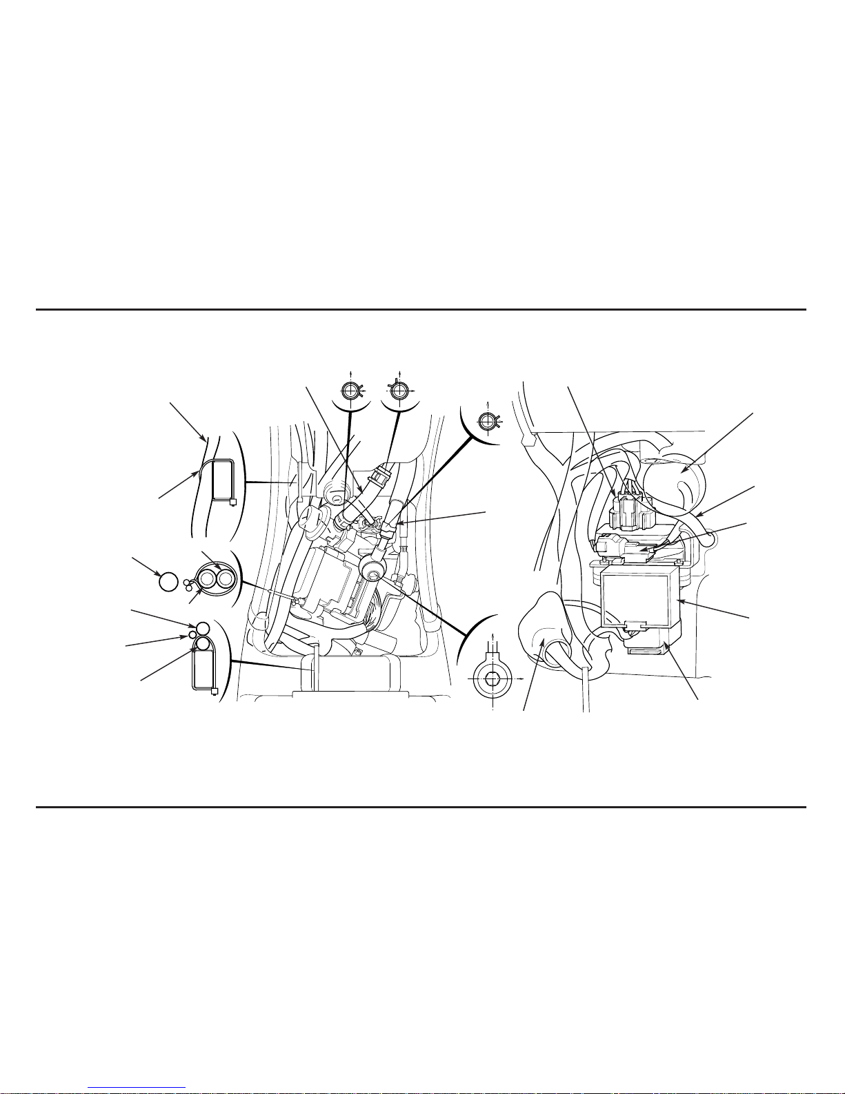
2-13
(2)
(1) WIRE HARNESS
(2) THROTTLE CABLE
(3) CLUTCH HOSE
(4) CONNECTOR BOOT
– FAN MOTOR 2P (BLACK) CONNECTOR
– POWER CONNECTOR
(4)
(5)
(7)
(8)
(9)
(1)
Clamp at white tape
(5) UPPER RADIATOR HOSE
(6) SPARK PLUG WIRE
(7) FAN MOTOR WIRE
(8) CRANKCASE BREATHER HOSE
(9) CRANKCASE BREATHER JOINT HOSE
(3)
(6)
Service Data
2-14
(1)
(1) INTAKE VACUUM HOSE
(2) THROTTLE CABLE
(3) CLUTCH HOSE
(4) FUEL TANK BREATHER HOSE
(2)
(2)
(3)
(4)
(4)
(3)
(2)
(3)
40 – 50˚
Service Data
2-15
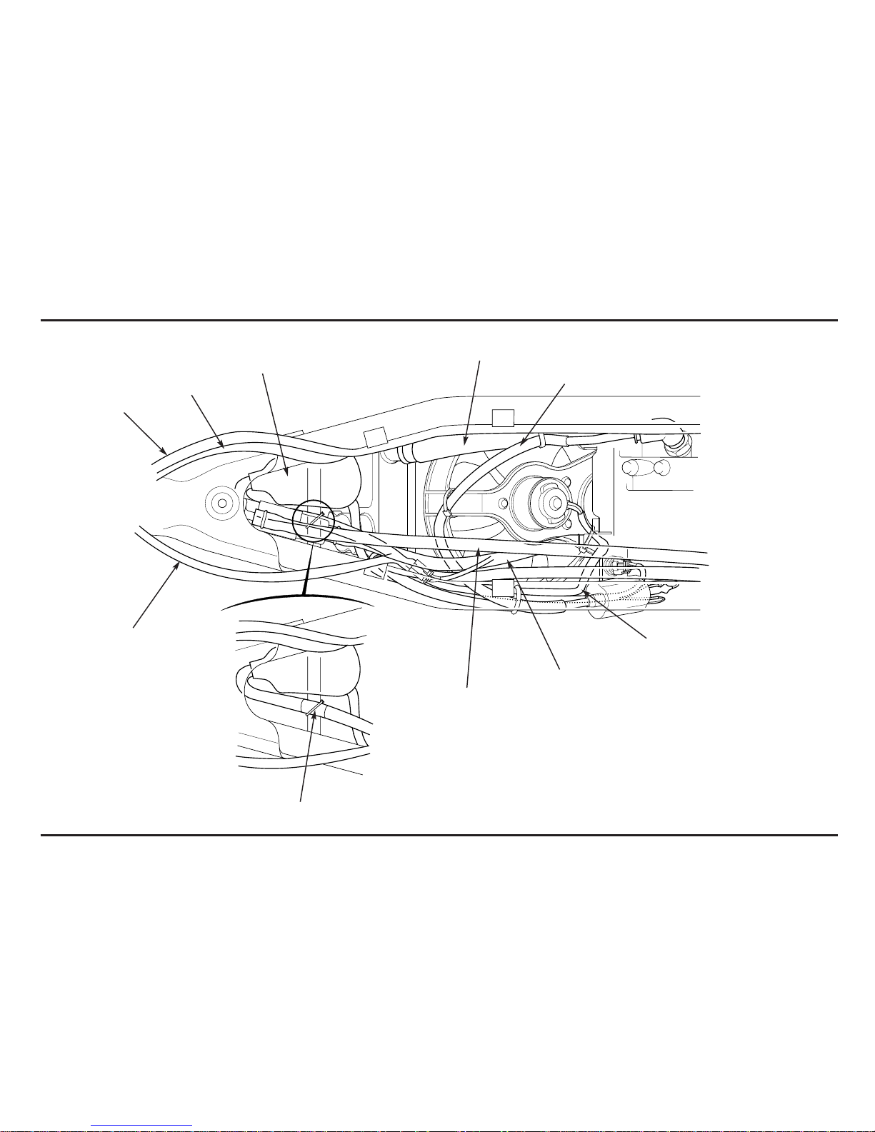
(1) MAIN WIRE HARNESS
(2) TRANSMISSION BREATHER HOSE
(3) CRANKCASE BREATHER JOINT HOSE
(4) ALTERNATOR WIRE
(5) CONDENSER 2P (BLACK) CONNECTOR
(6) REGULATOR/RECTIFIER 5P (BLACK) CONNECTOR
(1)
(2)
(3)
(6)
(5)
(4)
(7)
(8)
(9)
(7) ENGINE STOP RELAY
(8) FAN MOTOR RELAY
(9) REAR BRAKE RESERVOIR TANK
Service Data
2-16
(1)
(2)
(3)
(4)
(6)
(5)
(6)
(9)
(10)
(5)
(11)
(12)
(13)
(1) MAIN WIRE HARNESS (TO CONNECTOR COVER)
(2) MAIN WIRE HARNESS (TO RELAY)
(3) MAIN WIRE HARNESS (TO ECU)
(4) CRANKCASE BREATHER JOINT HOSE
(5) TRANSMISSION BREAHTER HOSE
(6) WIRE HARNESS
(7) FUEL RETURN HOSE
(8) FUEL FEED HOSE
(9) REGULATOR/RECTIFIER 5P (BLACK) CONNECTOR
(10) CONDENSOR
(11) CONDENSOR 2P (BLACK) CONNECTOR
(12) BANK ANGLE SENSOR
(13) FAN MOTOR RELAY
(14) CONNECTOR COVER
Clamp at white tape
(7)
(8)
(14)
Service Data
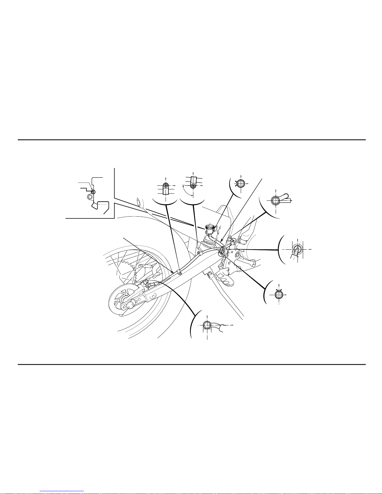
2-17
(1) REAR BRAKE HOSE
(2) REAR BRAKE RESERVOIR HOSE
(1)
(2)
90 – 95˚
Service Data
2-18
(1) FUEL FEED HOSE
(2) INTAKE VACUUM HOSE
(3) TRANSMISSION BREATHER HOSE
(1)
(2)
(3)
3. Service And Maintenance
3-1
Pre-ride Inspection
For your safety, it is very important to take a few moments
before each ride to walk around your COTA 4RT and
check its condition.
Improperly maintaining this COTA 4RT or failing to
correct a problem before riding can cause a crash in
which you can be seriously hurt or killed.
Always perform a Pre-ride and Pre-race inspection
before every ride and correct any problems.
Check the following items before you get on the COTA 4RT:
• Fuel, oil and water leaks
• Coolant for proper level
• Spark plug for proper heat range, carbon fouling and
spark plug cap terminals for looseness
•Clutch operation
• Steering head bearings and related parts for condition
• Damaged or distorted frame
• Throttle grip and throttle valve operation
•Tires for damaged or improper inflation pressure
•Front and rear suspension for proper operation
•Front and rear brakes, for proper operation
• Drive chain for correct slack and adequate lubrication
• Drive chain slider and roller for damage or wear
• Loose bolts, screws and other fasteners
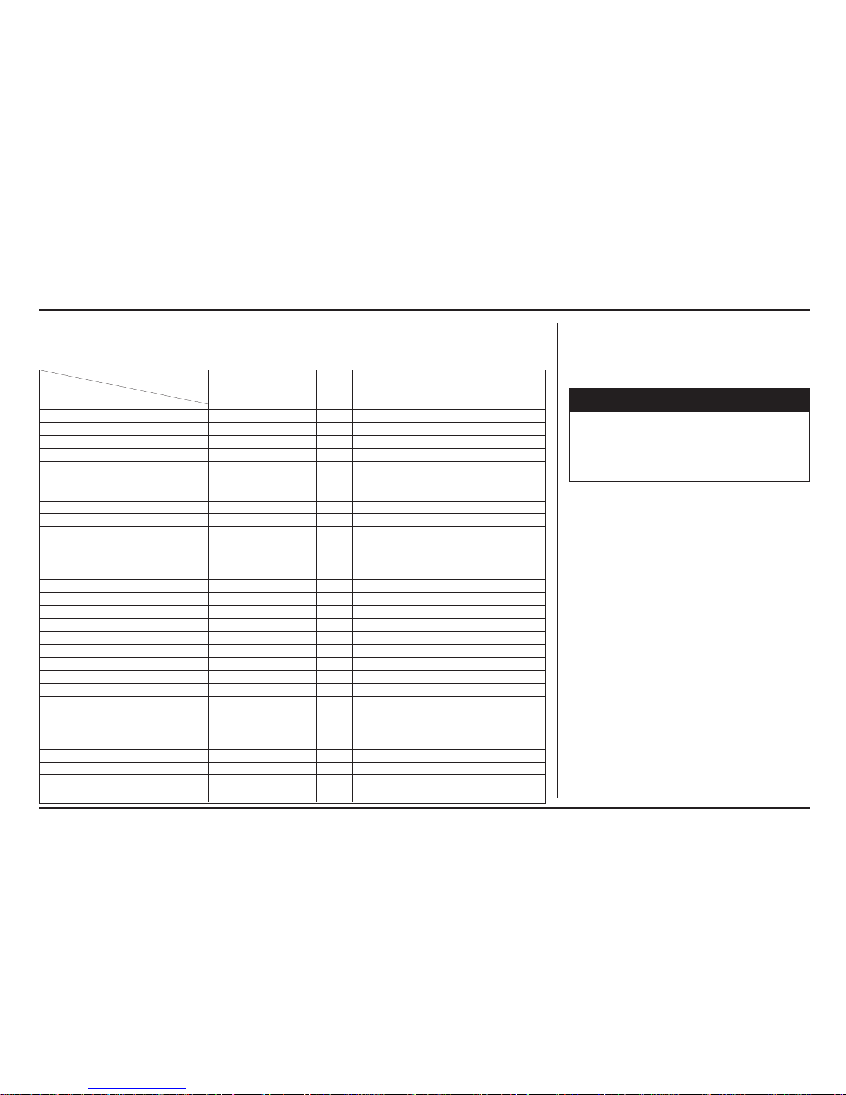
Maintenance Schedule
Perform pre-ride Inspection at each scheduled maintenance period.
I: Inspect and clean, Adjust, Lubricate or Replacement if necessary. C: Clean, R: Replace, L: Lubricate.
Frequency
Each race Every 6
or about races or Every half
Every
Remarks
2,5 h. about 15 h. a year
year
Item
Fuel Line I
Throttle Operation I
Air Cleaner C
Check the air cleaner after riding in dusty area
Spark Plug I R
Valve Clearance I I: After the first brake-in period
Engine Oil I R R: After the first brake-in period
Engine Oil Filter R R: After the first brake-in period
Engine Oil Strainer Screen I
Engine Idle Speed I
Transmission Oil R
Radiator Coolant I R
Cooling System I R
Piston I R
Piston Ring I R
Drive Chain I, L
Drive Chain Slider/Tensioner I
Drive/Driven Sprocket I
Brake Fluid I R
Brake Pad Wear I
Brake System I
Clutch Fluid I
Clutch System I
Control Cables I, L
Exhaust Pipe/Muffler I C
Suspension I C Check the spherical bearing damage.
Swingarm/Shock Linkage I C
Fork Oil I R
Wheels/Tires I
Steering Head Bearing I
Nuts, Bolts, Fasteners I
!
WARNING
Service And Maintenance
3-2
Warming-up Inspection
When warming-up the engine, check for the following:
• Do not rev the engine more than necessary or engine
damage may result.
• Check for fuel, oil and water leaks
•Warm up the engine for a few minutes until it is heated
to the operating temperature until the engine
responds to the throttle smoothly.
Ride Inspection
When running the COTA, check for the following:
• Control system
• Brake stopping power
After Ride Inspection
After riding the COTA, check for the following:
• Color condition of piston head and spark plug
• Signs of detonation
• Fuel, oil and water leaks
• Loose or missing bolts and nuts
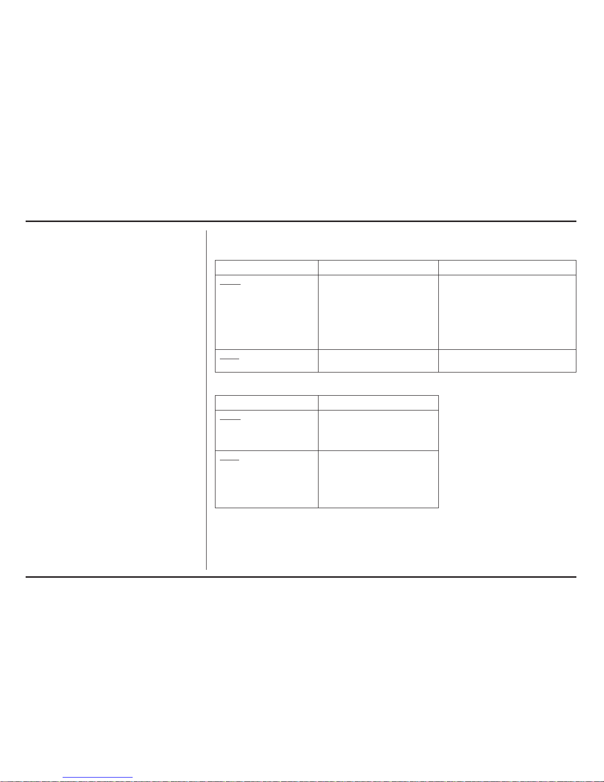
Replacement Parts
Parts Requiring Periodic Replacement
Item Replacement Interval Cause
Engine
Spark plug/plug cap Every 6 races Contamination or emulsification
Engine oil Every 6 races
Engine oil filter Every 6 races
Transmission oil Every 6 races
Piston Every year Damage or wear at skirt
Piston ring Every half a year Damage at ends or wear
Radiator coolant Every year
Frame
Front fork fluid Every half a year
Fast Wearing/Expendable Parts
Item Cause
Engine
Clutch disc Wear or discoloration
Clutch spring Fatigue
Drive sprocket Wear or damage
Frame
Front/rear tire Wear
Brake pad Wear
Chain slider Wear
Driven sprocket Wear or damage
Drive chain Elongation or wear
 Loading...