

Monte Carlo Fan Company ESSWC-3-WH/AL-ENG, ESSWC-3-WH-ENG, ESSWC-3-AL-ENG Operation Manual
8/31/04
ESSWC-3-WH/AL-ENG
Installation & Operating Instructions
Ceiling Fan Slide Wall Control
WARNING: SHUT POWER OFF AT FUSE OR CIRCUIT BREAKER
1. SAFETY PRECAUTIONS:
WARNING: To avoid fire, shock, and serious personal
injury, follow all instructions carefully. Read your Owner’s
Manual carefully before installing the ceiling fan control.
Retain Owner’s Manual for future reference.
2. To avoid possible electrical shock, be sure electricity is
turned off at the main fuse box or circuit breaker panel
before wiring.
3. This control is designed to operate only one ceiling fan
and not an accessory light kit. This wall control is rated
for 1.25 amps at 120 volts. If your ceiling fan is
equipped with a variable speed pull chain switch
control, make sure to set it at the highest speed
before installing the wall control. This will avoid
erratic speeds and possible damage to your ceiling
fan.
4. Make certain no bare wires are exposed outside the
connectors.
5. All wiring must conform to National and Local Electrical
Codes. If you feel you do not have enough electrical wiring
knowledge or experience, have your fan control installed
by a licensed electrician. Any electrical work not described
in this manual should be performed by a licensed electrician.
6. Use of this control with some ceiling fans could result
in fire, shock and serious personal injury. Use this fan control only with capacitor speed controlled ceiling fans.
INSTALLATION
1. After electricity has been turned off at the main fuse
box or circuit breaker panel, remove the existing wall plate
and switch.
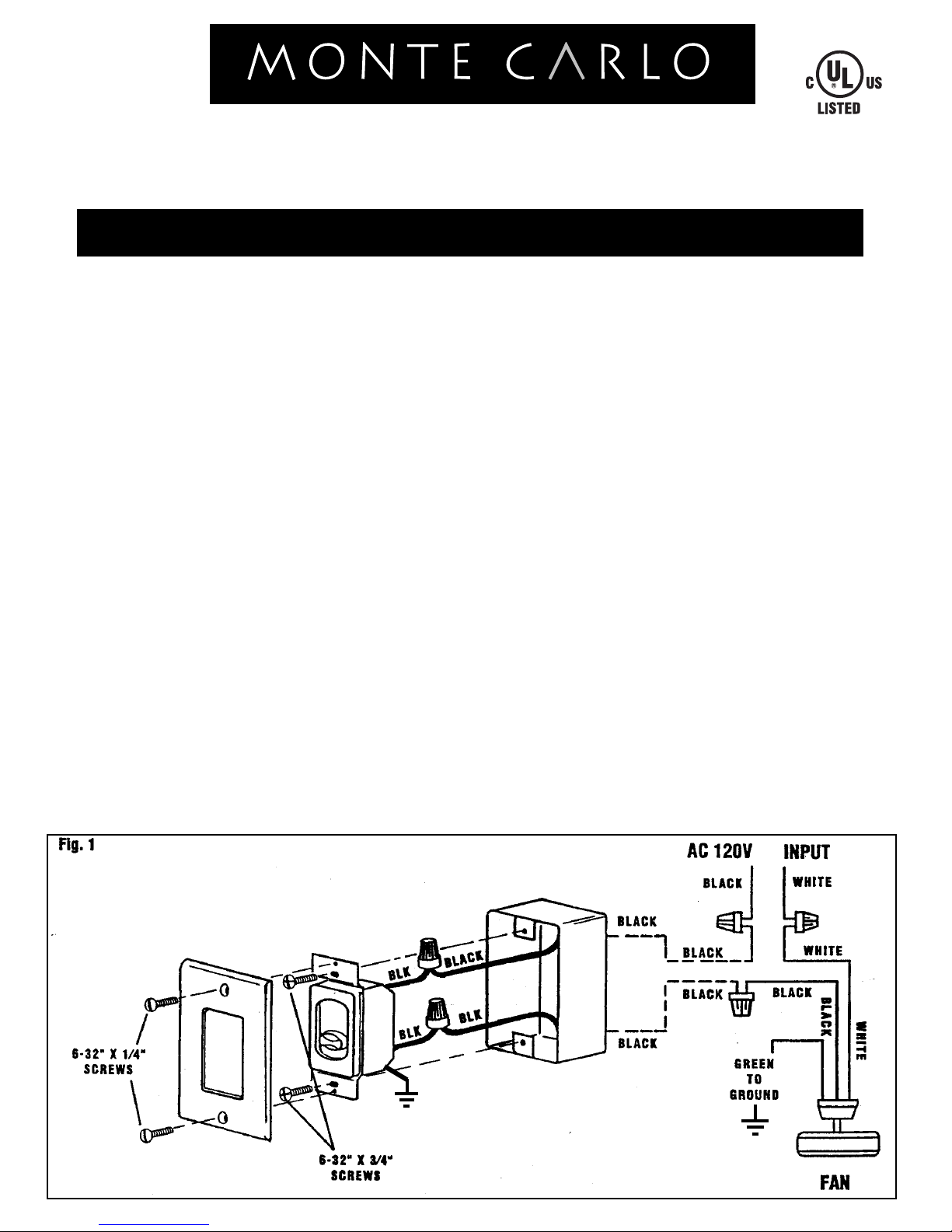
2. Proceed to make the wire connections as follows:
(make sure the switch is in the “OFF” position). Connect
one of the Black wires from the ESSWC-3 wall control to
the fan lead wire. Connect the second Black wire from the
ESSWVC-3 wall control to the 120v AC hot wire. Use wire
connectors provided to secure the connections.
NOTE: Refer to the Schematic on the back of the wall
control.
3. Secure the ESSWC-3 wall control to the outlet box
using the two 6-32” x 3/4” screws provided.
4. Secure the face plate over the wall control with the
two 6-32” x 1/4” screws provided.
5. Ground from wall control to ground coming into outlet
box.
WARNING! HOOK UP “IN SERIES” ONLY!
Do not connect to hot and common wire of electrical circuit
or switch will be damaged. Refer to diagram below
GREEN TO
GROUND

8/31/04
8/19/04 REV.0 ESSWC-4-WH-AL
 Loading...