

Monte Carlo Fan Company 5SBR56XXD-L, AC-556LF4000 Owner's Manual
Owner’s Guide and Installation Manual
Attach sales receipt to this card and retain as your proof of purchase
DATE OF PURCHASE:
MODEL NUMBER:
RETAILER NAME:
RETAILER ADDRESS:
To register your fixture, please visit our website www.montecarlofans.com
5SBR56XXD-L Series Fan
Total fan weight with light kit
UL Model No. : AC-556LF4000
18.5 kgs
40.7 lbs
© 2011 Monte Carlo Fan Company
5/10/2012
2
WARNING: TO REDUCE THE RISK OF FIRE, ELECTRIC SHOCK, OR INJURY TO PERSONS, OBSERVE THE FOLLOWING
READ AND SAVE THESE INSTRUCTIONS
Installation work and electrical wiring must be done by qualified person(s) in accordance with applicable codes and standards (ANSI/NFPA
70-1999), including fire-rated construction.
Use this unit only in the manner intended by the manufacturer. If you have any questions contact the manufacturer.
After making the wire connections, the wires should be spread apart with the grounded conductor and the equipment-grounding conductor
on one side of the outlet box and ungrounded conductor on the other side of the outlet box. The splices, after being made, should be
turned upward and pushed carefully up into the outlet box.
WARNING: Before you begin installing the fan, servicing or cleaning unit, Switch power off at Service panel and lock service disconnecting
means to prevent power from being switched on accidentally. When the service disconnecting means cannot be locked, securely fasten a
prominent warning device, such as a tag, to the service panel.
Be cautious! Read all instructions and safety information before installing your new fan. Review the accompanying assembly diagrams.
When cutting or drilling into wall or ceiling, do not damage electrical wiring and other hidden utilities.
Make sure the installation site you choose allows the fan blades to rotate without any obstructions. Allow a minimum clearance of 7 feet
from the floor to the trailing edge of the blade.
WARNING: To Reduce The Risk Of Fire, Electric Shock, or Personal Injury, Mount To Outlet Box Marked “Acceptable for Fan Support of
31.8 kg (70 lbs) or less” And Use Mounting Screws Provided With The Outlet Box.
CAUTION: For Compliance with Local Codes and Regulations, If Installing The Secondary Support Safety Cable in the U.S., Do Not Remove Knockouts In The Outlet Box. Mount the secondary support safety cable through the reserved nail/screw hole on the outlet box to
the building structure (or the ceiling joist).
WARNING: To reduce the risk of personal injury, do not bend blade holders during installation to motor, balancing or during cleaning. Do
not insert foreign object between rotating blades.
Attach the mounting bracket using only the hardware supplied with the outlet box.
WARNING: To reduce the risk of fire or electric shock, this fan must be installed with an isolating wall control/switch.
WARNING: To reduce the risk of fire or electric shock, do not use this fan with any solid state fan speed control device, or variable speed
control.
If this unit is to be installed over a tub or shower, it must be marked as appropriate for the application.
Never place a switch where it can be reached from a tub or shower.
The combustion airflow needed for safe operation of fuel-burning equipment may be affected by this unit’s operation. Follow the heating
equipment manufacturer’s guideline safety standards such as those published by the National Fire Protection Association (NFPA), and the
American Society for Heating, Refrigeration and Air Conditioning Engineers (ASHRAE) and the local code authorities.
CAUTION: To Reduce the Risk of Electric Shock, Disconnect the electrical supply circuit to the fan before installing the light kit.
All set screws must be checked and tightened where necessary before installation.
Customer Service
800-969-3347
Customer Service Center
7400 Linder Ave.
Skokie, IL 60077
www.montecarlofans.com
Tools Required for Assembly (not included): Electrical Tape, Phillips Screwdriver, Pliers, Safety Glasses,
Stepladder and Wire Strippers.
© 2011 Monte Carlo Fan Company
5/10/2012
3
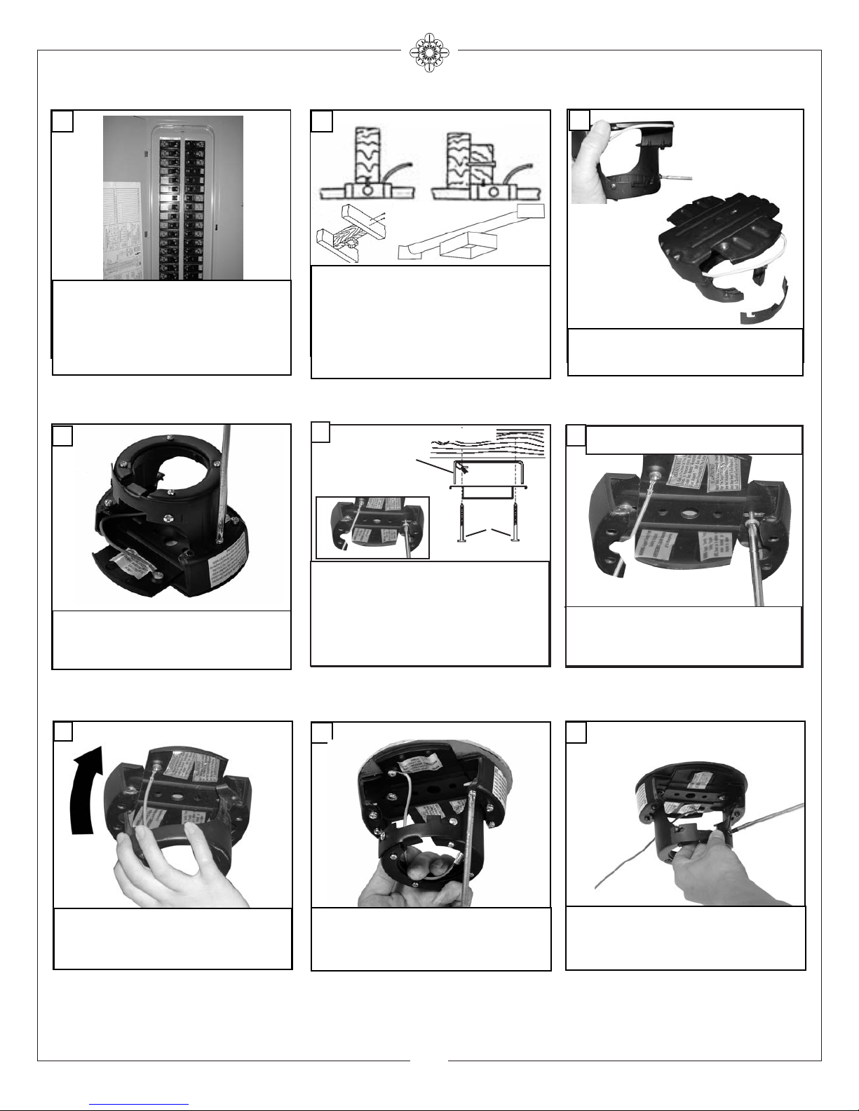
Before you begin installing the fan, Switch
power off at Service panel and lock service disconnecting means to prevent power from being
switched on accidentally. When the service disconnecting means cannot be locked, securely
fasten a prominent warning device, such as a
tag, to the service panel.
Warning-Risk of fire, electric shock, or personal injury. The fan in this box may be either
directly supported from a structural framing
member of a building and/or may be mounted
to an outlet box marked acceptable for fan support of of 31.8 kg (70 lbs) or less. Most outlet
boxes commonly used for the support of lumminaires may not be acceptable for fan support
and may need to be replaced. Consult a qualified electrician if in doubt.
21
OUTLET BOX METHOD
Remove Safety bar from mounting bracket by
loosing screws, sliding bar to side, and lifting it
off the 2 screws.
3
Remove the 6 screws attaching the Mounting
neck the mounting plate. Retain the 6 screws
for re-assembly.
4
Loosen 2 screws and remove gate.
Save gate for use later.
9
Lift mounting neck to mounting Plate
and align screws.
7
Secure mounting neck to the mounting plate with 6 screws to become
a complete mounting bracket.
8
Secure mounting plate directly to a joist from
the buliding structure via the two knock out
holes on the outlet box. Use only the appropriate wood screws and washers included with
your fan.
Caution: Wood screws must go through into
the building joist.
Note:If Installing It In The U.S., Do Not Remove Knockouts In The Outlet Box
5
Outlet box
Mounting
Plate
Wood
Screws
BUILDING STRUCTURE METHOD
Install the mounting Plate to approved fan
brace and box combination use only the hardware provided with the fan brace and box.
6
FAN BRACE AND OUTLET BOX METHOD
For Installation in The U.S. only
 Loading...