

Monte Carlo Fan Company 3FSR52, 3FSR52XXD Instructions Manual
R
MonteCarloFans.com
3FSR52XXD Series Fan
UL Model No. : AC-552LF8700H
Total fan weight
with light kit
READ AND SAVE
THESE INSTRUCTIONS
Si necesita asistencia en la instalación,
piezas de repuesto, o tiene preguntas
acerca de nuestra garantía, por favor
llame a nuestro centro de servicio
al cliente:
Si vous avez besoin d'aide pour l'installation,
des pièces de remplacement, ou si vous avez
des questions concernant notre garantie,
veuillez contacter notre service après-vente:
If you need installation
assistance, replacement parts,
or have questions regarding
our warranty, please call our
customer care center:
NEED HELP?
¿NECESITA AYUDA?
AVEZ-VOUS BESOIN D’AIDE?
Please do not return this product to the store.
Por favor no devulva este producto a la tienda.
Prière de ne pas retourner ce produit au magasin.
1-800-519-4092
MonteCarloFans.com
STOP ALTO
To register your fixture, please visit our website:
MonteCarloFans.com
shown with light
shown without light
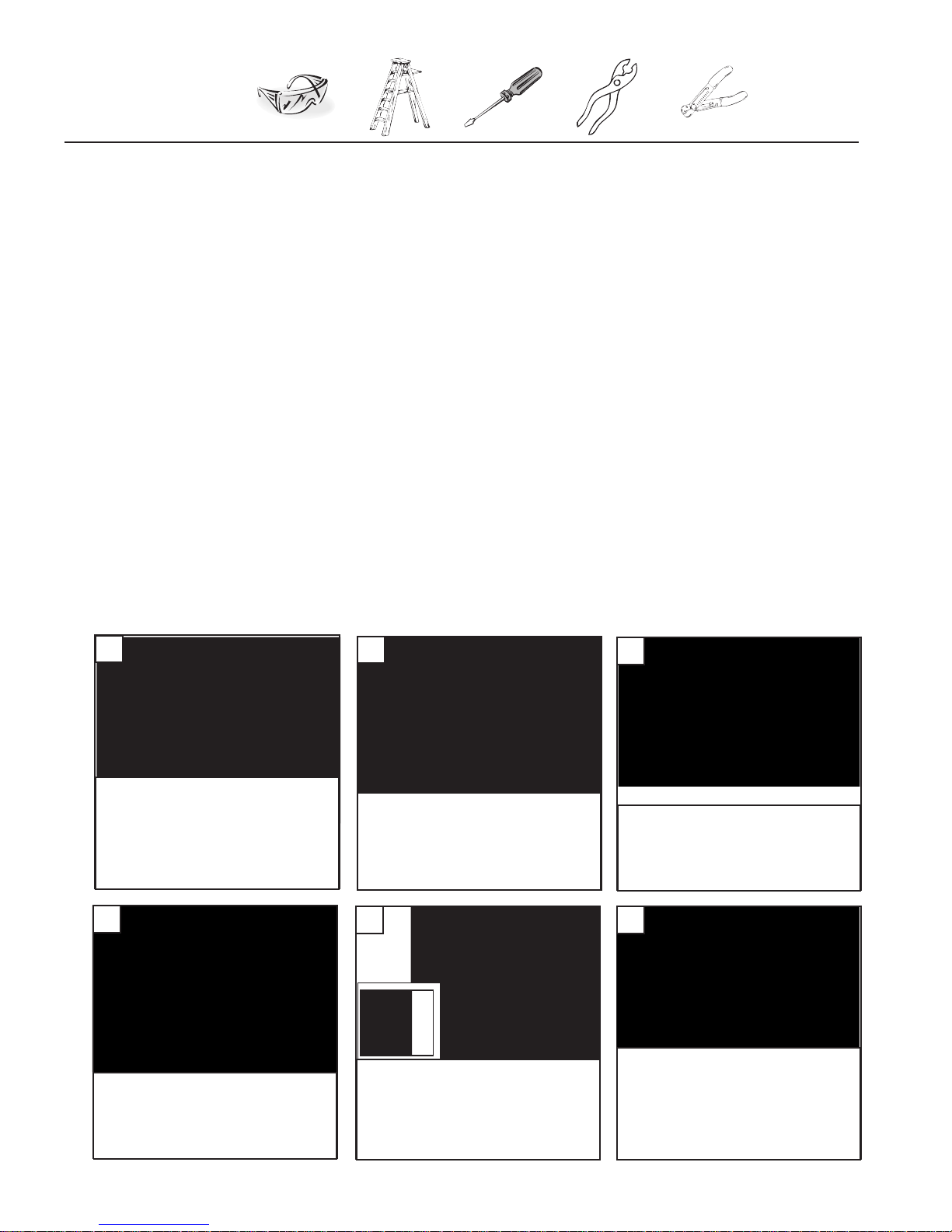
1
Before you begin installing the fan, Switch
power off at Service panel and lock service
disconnecti ng means to prevent p ower
from being switched on accidentally. When
the service disconnecting means cannot
be locked, securely fasten a prominent
warning device, such as a tag, to the
service panel.
2
Be for e insta llin g this fan m ake sur e the
outlet box is properly installed to the house
structure. To reduce the risk of re, electric
shock, or personal injury, mount to outlet
box or supporting system acceptable for fan
support.
(Mounting must support at least 35 lbs.)
3
Remove preassembled hex nuts
from mounting plate. Save for
later use.
4
Thread safety cable through center
hole of the mounting plate. Thread
your house wires through center
hole also.These will be needed for
wiring of the fan.
5
6
Securely attached the mounting
plate to the outlet box using two
screws supplied by the outlet box.
Use metal outlet box suitable for fan
support (must support 35 lbs).
Safety instructions
Helpful Tools
WARNING: TO REDUCE THE RISK OF FIRE, ELECTRIC SHOCK, OR INJURY TO PERSONS, OBSERVE
THE FOLLOWING: READ AND SAVE THESE INSTRUCTIONS
Installation work and electrical wiring must be done by qualied person(s) in accordance with applicable codes and standards (ANSI/NFPA
70-1999), including re-rated construction.
Use this unit only in the manner intended by the manufacturer. If you have any questions contact the manufacturer.
After making the wire connections, the wires should be spread apart with the grounded conductor and the equipment-grounding conductor
on one side of the outlet box and ungrounded conductor on the other side of the outlet box. The splices, after being made, should be
turned upward and pushed carefully up into the outlet box.
WARNING: Before you begin installing the fan, servicing or cleaning unit, Switch power off at Service panel and lock service
disconnecting means to prevent power from being switched on accidentally. When the service disconnecting means cannot be locked,
securely fasten a prominent warning device, such as a tag, to the service panel.
Be cautious! read all instructions and safety information before installing your new fan. Review the accompanying assembly diagrams.
When cutting or drilling into wall or ceiling, do not damage electrical wiring and other hidden utilities.
Make sure the installation site you choose allows the fan blades to rotate without any obstructions. Allow a minimum clearance of 7 feet
from the oor to the trailing edge of the blade.
WARNING: To reduce the risk of re, electric shock, or personal injury, mount to outlet box marked “acceptable for fan support” and use
mounting screws provided with the outlet box (Mounting must support at least 35 lbs.)
WARNING: To reduce the risk of personal injury, do not bend blade holders during installation to motor, balancing or during cleaning. Do
not insert foreign object between rotating blades.
Attach the mounting bracket using only the hardware supplied with the outlet box.
WARNING: To reduce the risk of re or electric shock, this fan must be installed with an isolating wall control/switch.
WARNING: To reduce the risk of fire or electric shock, this fan should only be used with fan speed control part no. UC7067RY
manufactured by Rhine Electronic Co., Ltd.
WARNING: To reduce the risk of re or electric shock, do not use this fan with any solid state fan speed control device, or variable speed
control.
If this unit is to be installed over a tub or shower, it must be marked as appropriate for the application.
Never place a switch where it can be reached from a tub or shower.
The combustion airow needed for safe operation of fuel-burning equipment may be affected by this unit’s operation. Follow the heating
equipment manufacturer’s guideline safety standards such as those published by the National Fire Protection Association (NFPA), and the
American Society for Heating, Refrigeration and Air Conditioning Engineers (ASHRAE) and the local code authorities.
CAUTION: To Reduce the Risk of Electric Shock, Disconnect the electrical supply circuit to the fan before installing the light kit.
All set screws must be checked and tightened where necessary before installation.
1.
2.
3.
4.
5.
6.
7.
8.
9.
10.
11.
12.
13.
14.
15.
16.
17.
18.
Lag screw
Lag screw
Washer
Lock washer
Safety cable
Safety cable
For Canadian installation and for USA fan and
light kit combinations over 35 lbs, in both
ush and downrod mode the safety cable must
be installed into the house structure beams
using the 3” lag screws provided. Make sure
that when the safety cable is fully extended
the leadwires are longer than the cable and no
stress is placed on the leadwires.
 Loading...