

Monte Carlo Fan Company 3DIR52XXD Owner's Manual
Owner’s Guide and Installation Manual
Attach sales receipt to this card and retain as your proof of purchase
DATE OF PURCHASE:
MODEL NUMBER:
To register your fixture, please visit our website www.montecarlofans.com
RETAILER NAME:
RETAILER ADDRESS:
3DIR52XXD Series Fan
UL Model NO. : 3DIR52XXD
8.2 kgs
18 lbs
Total fan weight with light
Cautions and Warnings
WARNING: TO REDUCE THE RISK OF FIRE, ELECTRIC SHOCK, OR INJURY TO PERSONS, OBSERVE THE FOLLOWING
READ AND SAVE THESE INSTRUCTIONS
Installation work and electrical wiring must be done by qualified person(s) in accordance with applicable codes and standards (ANSI/NFPA 70) including
fire-rated construction.
Use this unit only in the manner intended by the manufacturer. If you have any questions contact the manufacturer.
After making the wire connections, the wires should be spread apart with the grounded conductor and the equipment-grounding conductor on one side
of the outlet box and ungrounded conductor on the other side of the outlet box. The splices, after being made, should be turned upward and pushed
carefully up into the outlet box.
WARNING: Before you begin installing the fan, servicing or cleaning unit, Switch power off at Service panel and lock service disconnecting means to
prevent power from being switched on accidentally. When the service disconnecting means cannot be locked, securely fasten a prominent warning
device, such as a tag, to the service panel.
Be cautious! Read all instructions and safety information before installing your new fan. Review the accompanying assembly diagrams.
When cutting or drilling into wall or ceiling, do not damage electrical wiring and other hidden utilities.
Make sure the installation site you choose allows the fan blades to rotate without any obstructions. Allow a minimum clearance of 7 feet from the floor
to the trailing edge of the blade.
WARNING: To Reduce The Risk Of Fire, Electric Shock, or Personal Injury, Mount To Outlet Box Marked “Acceptable for Fan Support of 15.9 kg (35 lbs)
or less” And Use Mounting Screws Provided With The Outlet Box.
CAUTION: For Compliance with Local Codes and Regulations, If Installing The Secondary Support Safety Cable in the U.S., Do Not Remove Knockouts
In The Outlet Box. Mount the secondary support safety cable through the reserved nail/screw hole on the outlet box to the building structure (or the
ceiling joist).
WARNING: To reduce the risk of personal injury, do not bend blade holders during installation to motor, balancing or during cleaning. Do not insert
foreign object between rotating blades.
Attach the mounting bracket using only the hardware supplied with the outlet box.
WARNING: To reduce the risk of fire or electric shock, this fan must be installed with an isolating wall control/switch.
WARNING: To reduce the risk of fire or electric shock, this fan should only be used with fan speed control part no. UC7067RA manufactured by Rhine
Electronic Co., Ltd.
WARNING: To reduce the risk of fire or electric shock, do not use this fan with any other solid state fan speed control device, or variable speed control.
If this unit is to be installed over a tub or shower, it must be marked as appropriate for the application.
Never place a switch where it can be reached from a tub or shower.
The combustion airflow needed for safe operation of fuel-burning equipment may be affected by this unit’s operation. Follow the heating equipment
manufacturer’s guideline safety standards such as those published by the National Fire Protection Association (NFPA), and the American Society for
Heating, Refrigeration and Air Conditioning Engineers (ASHRAE) and the local code authorities.
CAUTION: To Reduce the Risk of Electric Shock, Disconnect the electrical supply circuit to the fan before installing the light kit.
CAUTION: The light source is designed for this specific application and can overheat if serviced by untrained personnel. If any servicing is required, the
product should be returned to an authorized service facility for examination or repair.
All set screws must be checked and tightened where necessary before installation.
Note: Suitable for use in damp locations.
Tools Required for Assembly (not included): Electrical Tape, Phillips Screwdriver, Pliers, Safety Glasses, Stepladder and Wire Strippers
© 2015 Monte Carlo Fan Company
Customer Service
800-969-3347
Customer Service Center
7400 Linder Ave.
Skokie, IL 60077
www.montecarlofans.com
2
9/15/2015
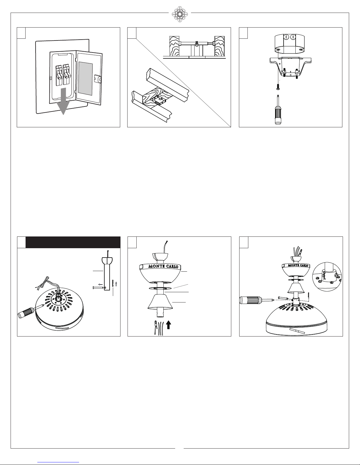
1 2 3
ON
ON
OFF
OFF
Mounting bracket
Before you begin installing the fan, Switch
power off at Service panel and lock
service disconnecting means to prevent
power from being switched on
accidentally. When the service
disconnecting means cannot be locked,
securely fasten a warning device, such
Before installing this fan make sure the
outlet box is properly installed to the
house structure. To reduce the risk of
fire, electric shock, or personal injury,
mount to outlet box or supporting system
acceptable for fan support.
(Mounting must support at least 35 lbs.)
as a tag, to the service panel.
Use AC 120V/60HZ power supply
only.
4 5 6
Downrod Mount Installation
Downrod
Cross pin
Keeper pin
Canopy
Canopy bottom ring
Downrod
Yoke cover
Use metal outlet box suitable for fan
support and use only the screws provided
with the outlet box (must support 35 lbs).
Before attaching fan to outlet box, ensure
the outlet box is securely fastened by at
least two points to a structural ceiling
member ( a loose box will cause the fan to
wobble). Remove the two outlet box
screws provided with the box, aligning
the holes of the mounting bracket with
the holes of the outlet box. Reinstall the 2
outlet box screws securely.
Cross pin
Keeper pin
Partially loosen downrod set screws from
yoke at top of motor assembly.
Remove preassembled cross pin and
keeper pin from downrod.
© 2015 Monte Carlo Fan Company
Place downrod over canopy, canopy
bottom ring and yoke cover. Thread lead
wires and safety cable from motor
assembly through downrod.
3
Slip downrod into motor housing yoke,
aligning holes and install cross pin and
keeper pin.
Insert cross pin through yoke and downrod
until point appears on the other side, and
insert keeper pin on cross pin.
Pull the downrod up tight against the
cross pin, and then evenly tighten the
downrod set screws on motor housing
yoke.
Place yoke cover on top housing of fan.
Warning: Cross pin and keeper pin must be
installed securely, failure to install them will
result in serious injury.
9/15/2015
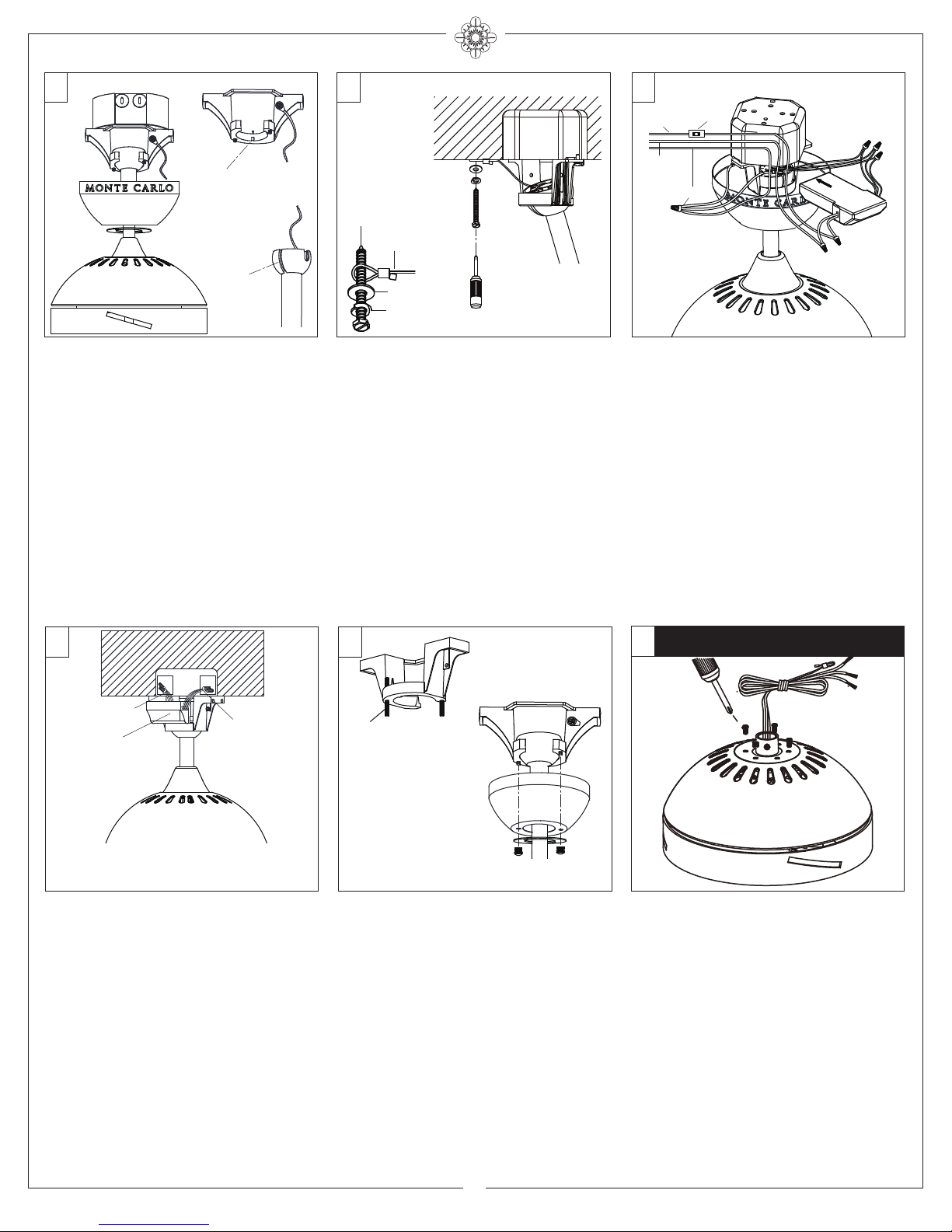
7 8 9
SAFETY CABLE INSTALLATION
Tab
Black
Wall switch
(Live)
White
Power source
(Neutral)
Ground/Green
White
Blue
Black
Slot
Install ball end of downrod into mounting
bracket opening. Align (engage) slot on
ball with tab on mounting bracket.
Warning: Failure to align slot on ball with
tab may result in serious injury.
Important: If using the angle mount,
make sure open end of mounting bracket
is installed facing the higher point of the
ceiling and make sure the ceiling angle is
not steeper than 30º.
For Canadian installation and for USA fan
and light kit combinations over 35 lbs, in
both flush and downrod modes the safety
cable must be installed into the house
structure beams using 3” lag screws,
washers and lock washers provided.
Make sure that when the safety cable is
fully extended the lead wires are longer
than the cable and no stress is placed on
the lead wires.
Note: If Installing The Secondary Support
Safety Cable in the U.S., Do Not Remove
Knockouts In The Outlet Box.
10 11
Lag screw
Safety cable
Washer
Lock washer
Receiver
Black
White
Make wiring connections using wire
connectors provided as indicated above.
White from fan to White from remote
marked N. Black from fan to Black from
remote marked L. Blue from fan to Blue
from remote marked FOR LIGHT. White
from house to White from remote marked
AC IN N. Black from house to Black from
remote marked AC IN L. Connect all
green grounded wires to Grounded wire
from House. Make sure that no filaments
are outside of the wire connectors.
Insert the remote receiver into mounting
bracket. Refer to page 7 for receiver
setting.
12
Flush Mount Installation
Grounded
wires
Receiver
After making the wire connections, the wires
should be spread apart with the grounded
conductor and the equipment-grounding
conductor on one side of the outlet box and
ungrounded conductor on the other side of
the outlet box. The splices after being made
should be turned upward and pushed carefully
up into the outlet box.
Ungrounded
wires
Stud
Lift Canopy allowing the 2 studs to protrude
through the canopy.
Next lift the cover ring and install knurled nuts
as shown. Tighten the knurled nuts securely.
The canopy should adjust for any irregularity
in the ceiling or Outlet box.
Make sure the studs protruding from the
bottom of the Mounting bracket are installed
with threads all the way through the bracket.
Go to step 20 to finish
installation
Remove every other screws from yoke
located on top of fan assembly. Keep
screws.
Note: Flush mount is not available with
vaulted ceiling.
© 2015 Monte Carlo Fan Company
4
9/15/2015
 Loading...