

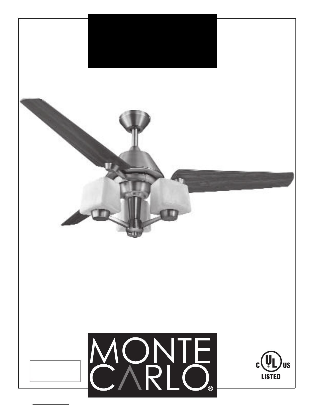
Monte Carlo Fan Company 3AXR52XX3-L Owner's Manual
OWNER’S
MANUAL
Ceiling Fan Installation Instructions
For 3AXR52XX3-L Series Fans
READ AND SAVE THESE INSTRUCTIONS
Total fan weight
with light kit
10.1kgs/22.3lbs
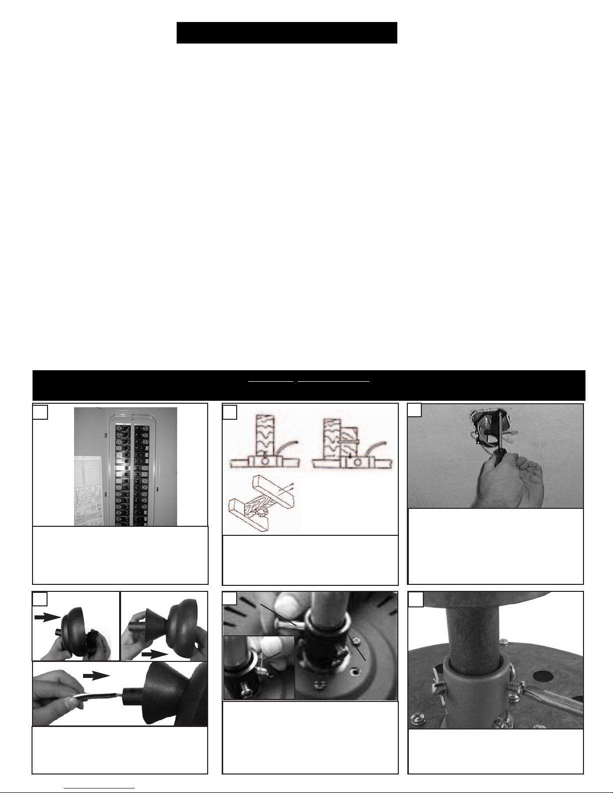
Installation
SAFETY TIPS
WARNING: TO REDUCE THE RISK OF FIRE, ELECTRIC SHOCK, OR INJURY TO PERSONS, OBSERVE THE
FOLLOWING: READ AND SAVE THESE INSTRUCTIONS
Installation work and electrical wiring must be done by qualified person(s) in accordance with applicable codes ANSI/NFPA 70-1999),
1.
including fire-rated construction.
Use this unit only in the manner intended by the manufacturer. If you have any questions contact the manufacturer.
2.
After making the wire connections, the wires should be spread apart with the grounded conductor and the equipment-grounding con-
3.
ductor on one side of the outlet box and ungrounded conductor on the other side of the outlet box.
Before you begin installing the fan, Switch power off at Service panel and lock service disconnecting means to prevent power from
4.
being switched on accidentally. When the service disconnecting means cannot be locked, securely fasten a prominent warning device,
such as a tag, to the service panel.
Be cautious! read all instructions and safety information before installing your new fan. Review the accompanying assembly diagrams.
5.
When cutting or drilling into wall or ceiling, do not damage electrical wiring and other hidden utilities.
6.
Make sure the installation site you choose allows the fan blades to rotate without any obstructions. Allow a minimum clearance of 7
7.
feet from the floor to the trailing edge of the blade.
To reduce the risk of fire, electric shock, or personal injury, mount to outlet box or supporting system acceptable for fan support and
8.
use only the screws provided with the outlet box. (Mounting must support at least 35 lbs.)
Do not bend blade holders during installation to motor, balancing or during cleaning. Do not insert foreign object between rotating
9.
blades.
Attach the mounting bracket using only the hardware supplied with the outlet box.
10.
To reduce the risk of fire or electric shock, this fan must be installed with an isolating wall control/switch.
11.
To reduce the risk of fire or electric shock, this fan should only be used with fan speed control part no. UC7067RC manufactured by
12.
Rhine Electronic Co., Ltd. Suitable for use with solid-state speed controls.
The combustion airflow needed for safe operation of fuel-burning equipment may be affected by this unit’s operation. Follow the heat-
13.
ing equipment manufacturer’s guideline safety standards such as those published by the National Fire Protection Association (NFPA),
and the American Society for Heating, Refrigeration and Air Conditioning Engineers (ASHRAE) and the local code authorities.
Before servicing or cleaning unit, Switch power off at Service panel and lock service disconnecting means to prevent power from being
14.
switched on accidentally. When the service disconnecting means cannot be locked, securely fasten a prominent warning device, such
as a tag, to the service panel.
Air flow direction: warm weather - switch to left - forward / cool weather - switch to right - reverse
Phillips Screwdriver Wire Cutters Pliers Step Ladder
Before you begin installing the fan, Switch
power off at Service panel and lock service disconnecting means to prevent power from being
switched on accidentally. When the service disconnecting means cannot be locked, securely
fasten a prominent warning device, such as a
tag, to the service panel.
4
Canopy
Downrod
Ball
Yoke cover
TOOLS REQUIRED
21
Before installing this fan make sure the outlet box is
properly installed to the house structure. To reduce
the risk of fire, electric shock, or personal injury,
mount to outlet box or supporting system acceptable
for fan support. (Mounting must support at least 35
lbs.)
Cross Pin
5
Keeper
Pin
Yoke
3
Use metal outlet box suitable for fan support
and use only the screws provided with the outlet box (must support 35 lbs). Before attaching
fan to outlet box, ensure the outlet box is
securely fastened by at least two points to a
structural ceiling member ( a loose box will
cause the fan to wobble). Use only the
screws provided with the outlet box.
6
Thread canopy and yoke cover on downrod. Thread leadwires and safety cable
through the downrod. Follow inserts as
shown above.
Loosen the 2 set screws in yoke for downrod to
slip into yoke. Insert downrod into yoke on top
of the Fan Body. Align the hole in the Downrod
with the hole in the Yoke. Insert the Pin
through the Yoke and Downrod until the point
appears on the other side. Install the Keeper
Pin.
Tighten the 2 Set screws on the Yoke
once the downrod is in place.
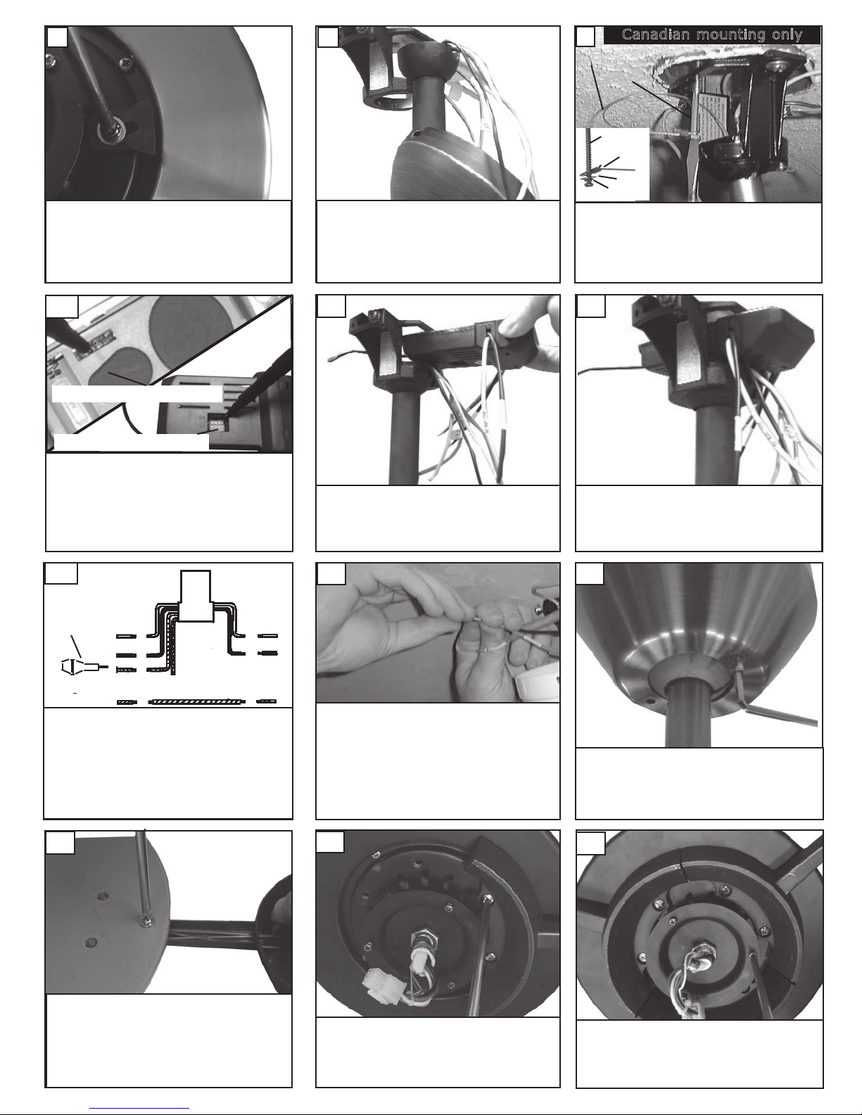
7
Remove the shipping stabilizers
attached to the motor.
8
Hang assembled fan from the mounting bracket
installed to ceiling in previous step. Make sure the
fan is hanging straight. Rotate fan until the tab on
the Mounting bracket engages the slot on the
Downrod Ball. This must be done to prevent the fan
body from rotating when the blades are in motion.
9
For Canadian installation in both flush and downrod mode the safety cable must be installed into
the house structure beams using the 3” lag screws
provided. Make sure that when the safety cable is
fully extended the leadwires are longer than the
cable and no stress is placed on the leadwires.
Canadian mounting only
Safety Cable
Lag Screw
Lag Screw
Safety Cable
Washer
Lock Washer
10
Remote Transmitter Dip swtiches
Remote Receiver Dip switches
Set dip switches on the Remote Transmitter and Remote
Receiver to the same settings. This must be done so the
units will communcate properly. If you have other fans you
can set to control from one transmitter by setting both
receivers the same as the transmitter. If you have more
than one fan with remote. You can set the dip switches to
different positiosns to have seperate control.
13
fuses
Make wiring connections as indicated above.
White from fan to white from remote marked
N. Blue from fan to blue from remote marked
light. Black from fan to Black from remote
marked L. White from house to white from
remote marked AC N . Black from house to
Black from remote marked AC L. Connect all
green ground wires to Ground wire from
House.
Fan
white
black
blue
Green
House
white
black
11
Install remote receiver into the
mounting bracket.
14
Make wire connections to power source using wire
nuts provided. Make sure that no filiments are outside of the wirenut. After making the wire connections, the wires should be spread apart with the
grounded conductor and the equipment-grounding
conductor on one side of the outlet box and ungrounded conductor on the other side of the outlet box. The
splices after being made should be turned upward and
pushed carefully up into the outlet box.
12
Ready for wiring.
15
Install t he canopy with the 2 hex
nut screws by usin g the hex-nut
driver provided(As shown).
Tighten hex- nut screws se curely.
16
Place blade brackets onto blades
aligning holes in blade bracket
with holes in blade. Install 3
screws and fiber washers to back
side of blade as shown. Tighten
screws securely. Repeat this
process 2 more times until all
blades are assembled.
17
Install blade and blade bracket
to motor
on the
securely.
with the screws
blade brackets. Tighten
pre-attached
assembly
screws
18
Loosen 2 screws and remove 1 screw
from motor plate. Save removed
screws for use later.
 Loading...