

W20 A
bi-amped
speaker system
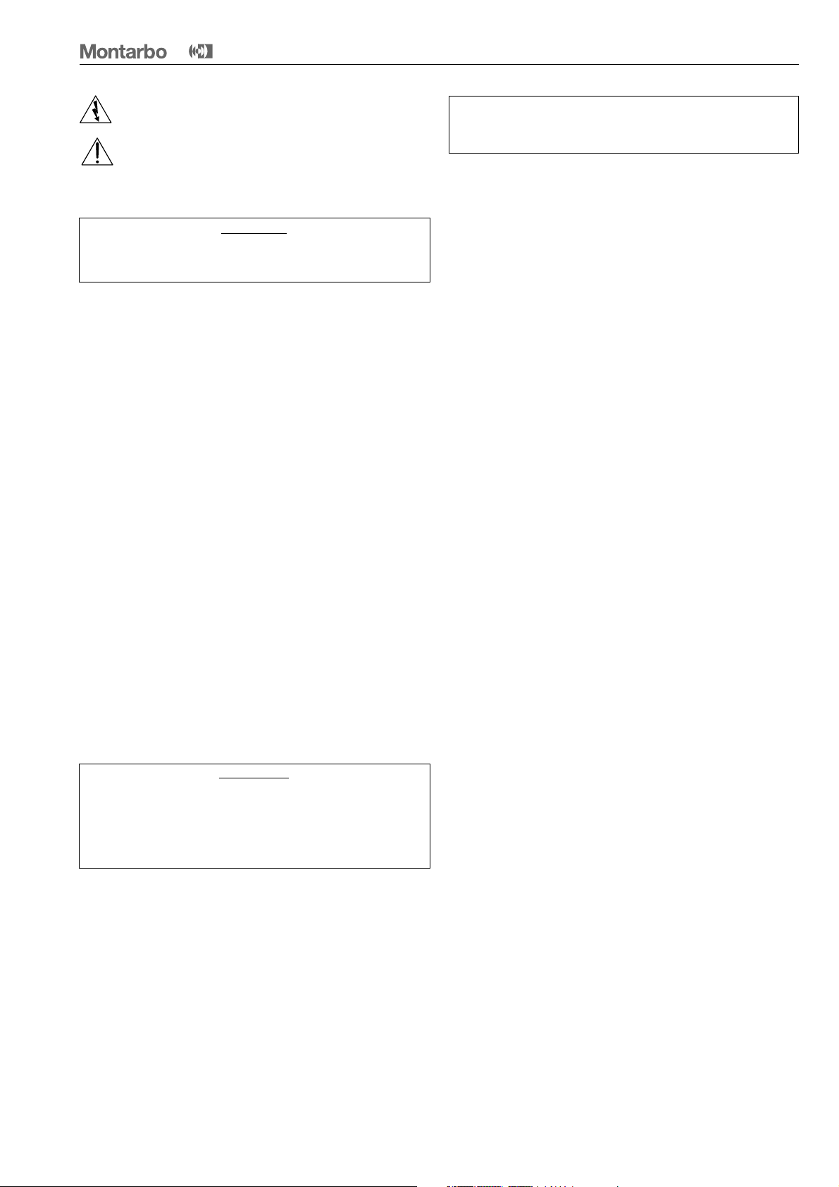
Il lampo con la freccia inserito in un triangolo equilatero avvisa l'utilizzatore della
presenza di tensione pericolosa, senza isolamento, all'interno dell'apparecchio che
potrebbe essere sufficientemente alta da generare il rischio di scossa elettrica.
Il punto esclamativo inserito in un triangolo equilatero avvisa l'utilizzatore della
presenza di importanti istruzioni per l'utilizzo e per la manutenzione nella
documentazione che accompagna il prodotto.
ITALIANO
W20
A
IMPORTANTE ! Norme di sicurezza
ATTENZIONE
Nell'interesse della propria e della altrui sicurezza, e per non
invalidare la garanzia, si raccomanda una attenta lettura di
questa sezione prima di adoperare il prodotto.
- Questo apparecchio è stato progettato e costruito per venire utilizzato
come sistema di altoparlanti con amplificatore nel contesto tipico di un
sistema di amplificazione sonora e/o di un sistema di registrazione sonora.
L'utilizzo per scopi diversi da questi non è contemplato dal costruttore, ed
avviene pertanto sotto la diretta responsabilità dell'utilizzatore/installatore.
PER EVITARE IL RISCHIO DI INCENDIO E/O DI FOLGORAZIONE:
• Non esporre il prodotto alla pioggia, non utilizzarlo in presenza di elevata
umidità o vicino all'acqua. Non lasciare penetrare all'interno dell'apparecchio
alcun liquido, né alcun oggetto solido. In caso ciò avvenga, scollegare immediatamente l'apparecchio dalla rete elettrica e rivolgersi ad un servizio di
assistenza qualificato prima di adoperarlo nuovamente.
• Prima di collegare l'apparecchio alla rete elettrica assicurarsi che la
tensione corrisponda a quella indicata sull'apparecchio stesso.
• Collegare questo apparecchio esclusivamente ad una presa di corrente
dotata di contatto di terra, rispondente alle norme di sicurezza vigenti, tramite il cavo di alimentazione in dotazione. Nel caso in cui il cavo necessiti
di sostituzione, utilizzare esclusivamente un cavo di identiche caratteristiche.
• Non appoggiare alcun oggetto sul cavo di alimentazione. Non posarlo
dove possa costituire intralcio e causare inciampo. Non schiacciarlo e non
calpestarlo.
• Installare questo apparecchio prevedendo ampio spazio circostante per
un'abbondante circolazione d'aria, necessaria al raffreddamento.
Non ostruire le aperture o le prese d'aria presenti sull'apparecchio.
• In caso di sostituzione del fusibile esterno, utilizzare esclusivamente un
fusibile di caratteristiche identiche, come riportato sull'apparecchio.
• Prima di effettuare qualsiasi operazione di collegamento, assicurarsi che
l'interruttore di accensione dell'apparecchio sia in posizione 'Off'.
• Prima di effettuare qualsiasi spostamento del prodotto già installato o in
funzione, rimuovere tutti i cavi di collegamento.
• Per scollegare l'apparecchio dalla rete elettrica, non tirare mai lungo il
cavo, ma afferrarlo sempre per il connettore.
ATTENZIONE!
Questo apparecchio non contiene parti interne destinate all'inter-
vento diretto da parte dell'utilizzatore. Per evitare il rischio di
incendio e/o folgorazione, non aprirlo. Per qualsiasi intervento
di manutenzione o riparazione, rivolgersi alla Elettronica
Montarbo srl e/o a personale altamente qualificato specificamen-
te segnalato da questa.
INDICE
Introduzione
__________________________________________
Descrizione
__________________________________________
__________________________________________
Pannello controlli e connessioni
__________________________________________
Importante !!!
__________________________________________
Appendix
__________________________________________
◗
Dati tecnici
__________________________________________
◗
Schema a blocchi
__________________________________________
◗
Connettori
__________________________________________
◗
Esempio di collegamento
__________________________________________
◗
Parti di ricambio
__________________________________________
10 - 15
3
3
4
5
11
12
13
14
15
- Nel predisporre l'apparecchio all'utilizzo, assicurarsi che la forma e la
portata della superficie di appoggio siano idonee a sostenerlo.
Non tentare mai di appendere il prodotto con mezzi non espressamente
forniti o approvati dal costruttore (corde, catene, funi o qualsivoglia altro
mezzo, attraverso maniglie, bulloni, ganci etc.). Nel caso il prodotto sia
dotato già dalla fabbrica di specifici accessori, verificare sempre, prima
dell'installazione, che il sistema di sollevamento e/o di sospensione che
intendete utilizzare sia di portata idonea al peso del prodotto.
- Per evitare urti, calci, inciampi riservate come luogo per l'istallazione del
prodotto un'area protetta inaccessibile a personale non qualificato.
Qualora l'apparecchio venga utilizzato in presenza di bambini e animali, si
rende necessaria una strettissima sorveglianza.
- Questo prodotto è in grado di generare pressioni acustiche molto elevate,
pericolose per la salute del sistema uditivo. Evitarne quindi l'utilizzo ad elevati livelli acustici se il pubblico si trova eccessivamente vicino al prodotto
(almeno ad 1 m di distanza). Non esporre i bambini a forti sorgenti sonore.
ITALIANO
2
Introduzione
W20
A
La cassa acustica bass reflex a 2 vie incorpora:
■
componenti di alta qualità realizzati su
nostre specifiche
■
2 amplificatori:
600 W RMS (bassi)
250 W RMS (medio/alti)
■
2 processori indipendenti
■
crossover elettronico 24dB/Oct
La cassa bass-reflex, costruita in multistrato di betulla
utilizza due woofer da 10" ad alta efficienza per le
frequenze basse ed una tromba a direttività costante
per le medio/alte, con driver dinamico da 2".
I due amplificatori di potenza sono controllati da un
crossover elettronico a 24dB/Oct. e da due processori
indipendenti che, ottimizzando la dinamica e la risposta in
frequenza, impediscono il sovraccarico elettrico e termico
dei componenti, aumentando così l’affidabilità del sistema.
La grande adattabilità di questa cassa alle diverse situazioni
di impiego consente di risolvere efficacemente ogni tipo di
installazione e di rispondere in maniera ottimale alle diverse
esigenze professionali di amplificazione e distribuzione del
suono.
Il pannello di controllo è dotato di ingressi bilanciati (prese
XLR maschio e femmina + Jack, collegate in parallelo) controllo volume ingresso, controllo attenuazione medio/alti,
commutatore ground-lift, interruttore di rete, presa di rete
con fusibile incorporato.
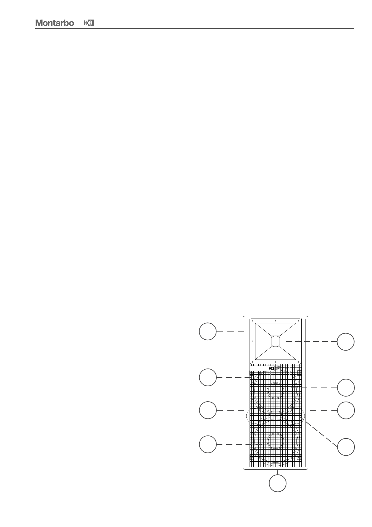
Descrizione
A Costruzione in multistrato di betulla ad incollaggio
fenolico; verniciatura poliuretanica.
B Tromba a direttività costante (dispersione 60° H x 40° V)
con driver dinamico da 2" (bobina mobile in piattina di
alluminio, centratore in kapton, diaframma in titanio).
C Due woofer 10" ad alta efficienza.
D Griglia in acciaio verniciato a polveri.
E Tubi di accordo.
F Maniglie laterali per il trasporto.
G Pannello controlli e connessioni.
H Adattatore per supporto cassa.
I materiali e la costruzione rispettano i più alti standard
professionali per assicurare la massima affidabilità.
A
D
F
C
B
Montarbo
C
G
E
H
ITALIANO
3
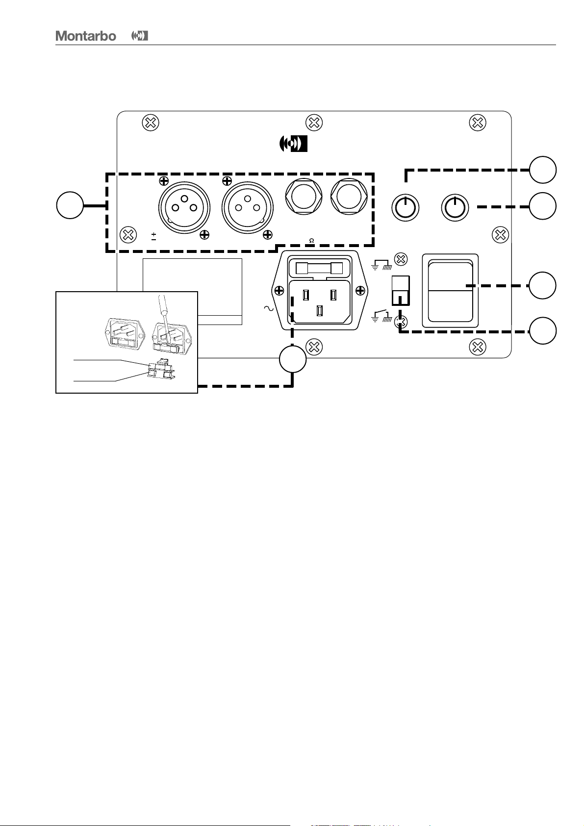
Pannello controlli e connessioni
W20
A
Montarbo
2 / WAY PROCESSOR CONTROLLED
ACTIVE SPEAKER SYSTEM
1
XLR
1 GND
2
SOSTITUZIONE FUSIBILE
Fusibile di servizio
Fusibile di riserva
3
CAUTION :
TO PREVENT ELECTRICAL SHOCK,
DO NOT REMOVE COVERS.
NO USER - SERVICEABLE PARTS INSIDE.
REFER SERVICING TO QUALIFIED
SERVICE PERSONNEL.
CAUTION :
TO PREVENT RISK OF FIRE
ALWAYS REPLACE FUSES
WITH SAME TYPE AND RATINGS.
POWER CONSUMPTION 1600W
LINKOUT IN
FUSE F
6,3 A
220V
50/60Hz
1 Il sistema acustico W20A è dotato di prese XLR maschio
(OUT) e femmina (IN) con jack collegati in parallelo.
Ciò rende possibile qualsiasi combinazione di collegamen-
ti con Jack o XLR ed inoltre semplifica il collegamento in
parallelo di più sistemi.
❚ uscita mixer ➔ ingresso W20A (prese 'IN' XLR o Jack)
❚ uscita W20A (prese 'OUT' XLR o Jack) ➔ ingresso della
W20A da collegare in parallelo (presa IN XLR o Jack).
10K 0,775V RMS
6
MOD.
POWER
20 A
W
600+250W
2
LINKOUT IN
GND
5
6
4
VOL.
7
8
9
100
3
2
1
5
6
4
H.F.
7
8
9
100
I
3
3
2
1
4
LIFT
0
5
4 Interruttore di rete (1/0).
5 Ground-lift (GND LIFT): scollega la massa dell’amplifica
tore dal telaio, pur conservando il collegamento a terra
di quest’ultimo.
Consente di ridurre i ronzii prodotti dai cosiddetti
'ground loops' (anelli di massa) nei collegamenti di più
apparecchi.
☛
Vedere i connettori e l'esempio di collegamento
alle pagine 13 e 14.
2 Volume generale (VOL). Permette di regolare i livelli di
ingresso dei 2 finali di potenza incorporati, per adattarli
al livello di uscita del mixer.
3 Volume frequenze alte (H.F.).
N.B: se utilizzate un mixer Montarbo, o comunque un
mixer avente livello di uscita 0dB, per un rendimento
ottimale consigliamo di regolare entrambi questi due
volumi al massimo (in senso orario).
6 Presa di rete con fusibile incorporato.
ITALIANO
4
Importante !
W20
A
Cura e manutenzione del prodotto:
• Posizionare la cassa lontano da fonti di calore (caloriferi o
qualsiasi altro oggetto che produca calore).
• Evitare di esporre la cassa alla irradiazione solare diretta,
ad eccessive vibrazioni e ad urti violenti.
• Evitare l'uso e il deposito in ambienti polverosi o umidi:
eviterete così cattivi funzionamenti e deterioramento anticipato delle prestazioni.
• Evitare l'uso vicino a fonti di interferenze elettromagnetiche
(monitor video, cavi elettrici di alta potenza) ciò potrebbe
compromettere la qualità audio.
• Proteggere la cassa dal rovesciamento accidentale di liquidi
o sostanze di qualsiasi tipo. In particolare nelle condizioni di
utilizzo tipiche, prestare la massima attenzione alla collocazione della cassa onde evitare che il pubblico, i musicisti,
i tecnici o chicchessia possa poggiare bicchieri, tazze,
contenitori di cibo o di bevande, posacenere o sigarette
accese sull'apparecchio.
• Per rimuovere la polvere usate un pennello o un soffio
d'aria, non usate mai detergenti, solventi o alcool.
Collegamento alla rete:
• Accertarsi che la tensione di rete corrisponda a quella indicata sul pannello (di fianco alla presa di alimentazione).
• Utilizzare il cavo di alimentazione a tre poli fornito insieme
alla cassa.
• Collegarlo ad una presa di corrente dotata di contatto di
terra.
Collegamento al mixer:
• Utilizzare sempre cavi SCHERMATI (cavi di segnale) di
adeguata sezione e di buona qualità.
• Prima di effettuare i collegamenti tra casse attive e mixer
accertarsi che tutti gli interruttori di rete siano spenti (0).
In tal modo si eviteranno fastidiosi rumori e picchi di segnale
talvolta pericolosi per le casse stesse.
☛ Vedere 'esempio di collegamento' a pagina 14.
Se il mixer ha uscite bilanciate:
- possono essere collegate indifferentemente agli ingressi
XLR o jack mediante connettori XLR o jack bilanciati.
• Abbiate cura dei cavi di collegamento, avvolgeteli evitando
nodi e torsioni.
• Non forzate i connettori ed i comandi.
• Non togliere la griglia di protezione.
• Accertarsi che l'interruttore di rete sia spento ('0') prima
di effettuare qualsiasi collegamento.
Se il mixer ha uscite sbilanciate XLR:
- nel caso in cui il mixer non sia un Montarbo, è bene
accertarsi che le uscite XLR del mixer siano sbilanciate a
norme IEC 268 e cioé: 1= GND, 2 = HOT, 3 = GND.
Se il mixer ha uscite sbilanciate Jack:
- potete collegarle ugualmente agli ingressi Jack mediante
dei connettori Jack mono (gli ingressi jack si sbilanceranno
automaticamente).
Collegamento in parallelo di più casse amplificate:
• Utilizzare sempre cavi SCHERMATI di adeguata sezione e
di buona qualità.
☛ Vedere 'esempio di collegamento' a pagina 14.
- utilizzare indifferentemente connettori XLR o Jack .
ITALIANO
5

The lighting flash with arrowhead symbol within an equilateral triangle, is
intended to alert the user to the presence of uninsulated 'dangerous voltage'
within the product's enclosure, that may be of sufficient magnitude to constitute
a risk of electric shock to humans.
The exclamation point within an equilateral triangle, is intended to alert the user
to the presence of important operating and maintenance (servicing) instructions in
the literature accompanying the product.
ENGLISH
W20
A
IMPORTANT ! SAFETY INSTRUCTIONS
WARNING
In order to protect your own and others' safety and to avoid
invalidation of the warranty of this product, please read this
section carefully before operating this product.
- This product has been designed and manufactured for being operated as
active speaker system in the applications tipical of a sound reinforcement
system or of a sound recording system. Operation for purposes and in
applications other than these has not been covered by the manufacturer
in the design of the product, and is therefore to be undertaken at end
user's and/or installer's sole risk and responsability.
TO AVOID THE RISK OF FIRE AND/OR ELECTRIC SHOCK:
• Never expose this product to rain or moisture, never use it in proximity
of water or on a wet surface. Never let any liquid, as well as any object,
enter the product. In case, immediately disconnect it from the mains supply
and refer to servicing before operating it again.
• Before connecting this product to the mains supply, always make sure
that the voltage on the mains outlet corresponds to that stated on the
product.
• This product must be connected only to a grounded mains outlet
complying to the safety regulations in force via the supplied power cable.
In case the power cable needs to be substituted, use exclusively a cable of
the same type and characteristics.
• Never place any object on the power cable. Never lay the power cable
on a walkway where one could trip over it. Never press or pinch it.
• Never install the product without providing adequate airflow to cool it.
Never obstruct the air intake openings on it.
• In case the external fuse needs replacement, substitute it only with one
of the same type and rating, as stated on the product.
• Always make sure the On/Off switch is in its 'Off' position before doing
any operation on the connections of the product.
• Before attempting to move the product after it has been installed,
remove all the connections.
• To disconnect the power cable of this product from the mains supply
never pull the cable directly instead, hold the body of the plug firmly and
pull it gently from the mains supply outlet.
CAUTION!
This product does not contain user serviceable parts.
To prevent fire and/or electrical shock, never remove its cover.
For maintenance and servicing always refer to the official
Montarbo Distributor in your State or to qualified personnel
specifically authorised by the Distributor.
- Before placing the product on a surface of any kind, always make sure
that its shape and load rating will safely match the product's size and
weight. Never attempt to hang the product by any means not expressly
provided or approved by the manufacturer (i.e. ropes, chains, belts or
whatever medium, throgh carring handles, bolts, hooks or whatever).
In case the product is factory-fitted with specific mounting hardware,
always verify before installation that the lifting and/or hanging system
you intend to use is of a proper type and can carry the product weight
with the safety ratio required by the regulations in force.
- To avoid shocks, kicks, or whatever action, always reserve a protected
area with no access to unqualified personnel as installation site of the
product. In case the product is used near children and animals closest
supervision is necessary.
- This product can generate very high acoustic pressures which are
dangerous for the hearing system. Always avoid operation at loud levels
if anyone is excessively near to the product (at least 1 m of distance).
Never expose children to high sound sources.
INDEX
Introduction
__________________________________________
Description
__________________________________________
Control and connection panel
__________________________________________
Important !!!
__________________________________________
Appendix
__________________________________________
◗ Specifications
__________________________________________
◗
Block diagram
__________________________________________
◗
Connectors
__________________________________________
◗
Connection example
__________________________________________
◗
Spare parts
__________________________________________
10 - 15
7
7
8
9
11
12
13
14
15
ENGLISH
6

Introduction
W20
A
The 2-way bass reflex enclosure incorporates:
■
custom designed, high quality components
■
2 amplifiers:
600 W RMS (bass)
250 W RMS (mid/high)
■
2 independent processors
■
24dB/Oct electronic crossover
The bass reflex enclosure, constructed from birch plywood,
is equipped with two custom designed 10" low frequency
woofers and a 2" driver with constant directivity horn
for the mid/high frequencies, each driven by its own dedicated power amplifier.
A high slope 24dB/Oct. electronic crossover and two
processors (one for each amplifier) optimize the dynamic
range and frequency response of the system, while protecting the drivers from thermal and electrical overloads, resulting in increased reliability and outstanding performance.
Its adaptability to various applications allows the W20A to
be used in any type of installation ensuring optimum results
to any professional requirement for sound reinforcement
and distribution.
The rear control panel is fitted with balanced inputs (male
and female XLRs + Jacks, wired in parallel), input volume
control, mid-high level control, ground-lift switch, mains
switch, mains socket with built-in fuse.
Description
A High grade birch plywood construction, phenolic glued;
polyurethane painted.
B Constant directivity, high frequency horn (dispersion
60° x 40°) with 2" dynamic driver (featuring aluminum
flat wire voice coil, kapton former, titanium dome).
C Two 10" high efficiency woofers.
D Powder coated, perforated, steel grid.
E Tunig ports.
F Side recessed handles.
G Control and connection panel.
H Speaker stand adaptor.
Construction and components conform to the highest
professional standards for maximum reliability.
A
D
F
C
B
Montarbo
C
G
E
H
ENGLISH
7

Control and connection panel
W20
A
Montarbo
2 / WAY PROCESSOR CONTROLLED
ACTIVE SPEAKER SYSTEM
1
XLR
1 GND
2
3
CAUTION :
TO PREVENT ELECTRICAL SHOCK,
DO NOT REMOVE COVERS.
NO USER - SERVICEABLE PARTS INSIDE.
REFER SERVICING TO QUALIFIED
SERVICE PERSONNEL.
CAUTION :
FUSE REPLACEMENT
Service fuse
Spare fuse
TO PREVENT RISK OF FIRE
ALWAYS REPLACE FUSES
WITH SAME TYPE AND RATINGS.
POWER CONSUMPTION 1600W
1 The W20A speaker system is equipped with XLR male
(OUT) and female (IN) sockets with jacks wired in parallel.
☛
See 'connectors' at page 13
This allows for any combination of Jack or XLR connections
with facility for daisy-chaining.
❚ Mixer output ➔ W20A input (XLR or Jack 'IN' sockets)
❚ W20A 'OUT' (XLR or Jack) ➔ input of the W20A to be
connected in series (XLR or Jack).
☛
See 'connection example' at page 14
LINKOUT IN
FUSE F
6,3 A
220V
50/60Hz
6
MOD.
POWER
LINKOUT IN
10K 0,775V RMS
20 A
W
600+250W
GND
LIFT
5
6
4
VOL.
7
8
9
100
3
2
1
5
6
4
H.F.
7
8
9
100
I
0
3
2
1
4 Mains power switch (1/ 0).
5 Ground-lift (GND LIFT): this switch allows to lift signal
ground from chassis ground (but the chassis is still
,
connected to the safety ground). This allows to lower
annoying hums caused by 'ground loops' when more
units are connected.
6 I.E.C. power supply socket with built-in fuse.
2
3
4
5
2 Main volume (VOL). Adjusts the input levels of the two
built-in power amplifiers to adapt them to the output
level of the mixer.
3 High frequencies level control (H.F.).
N.B: if you are using a Montarbo mixer (or any mixer
having an output level of 0dB), for optimum performance it is advisable to set both controls fully clockwise (to
their maximum settings).
ENGLISH
8

Important !
W20
A
Product Care and Maintenance
• Never expose the enclosure to heat sources such as radiators
or other products that produce heat.
• Never expose the enclosure to direct sunlight, excessive
vibrations or mechanical shocks.
• Avoid operating and storing the enclosure in damp or
dusty places: this will avoid malfunctions and premature
degrading of specifications.
• Avoid using the enclosure close to strong sources of
electromagnetic interferences (e.g. video monitors, high
power electrical cabling). This may lead to degradation of
audio quality.
• Care should be taken so that objects do not fall and liquid
are not spilled into the enclosure. In public event don't let
people, musicians, technicians or anyone put glasses, cups,
ashtrays or cigarettes on the enclosure.
• Use a soft brush or a jet of air to clean the enclosure.
Do not use alcohol, solvents or detergents.
• Take care of your connector cables. Make sure that they
are not damaged, knotted or twisted.
• Do not force connectors and controls.
• Do not remove the protection grid.
Power supply connection:
• Make sure the system is switched off ('0').
• Check that mains voltage corresponds to the voltage
indicated on the panel (beside the main socket).
• Use the three wire power cord supplied with the enclosure.
• Always connect it to a grounded outlet.
Connection to the mixer:
• Always make sure to use only heavy gauge, high quality
SHILDED cables (signal cables).
• Always make certain that the mixer and the powered
enclosures are switched off before connecting them.
This will avoid annoying noises and signal peaks, which can
also be dangerous for the enclosures themselves.
☛ See 'connection example' at page 14.
If the mixer has balanced outputs:
- they can be connected to the XLR or to the Jack inputs,
without distinction, using balanced XLR or Jack connectors.
If the mixer has XLR unbalanced outputs:
- unless you are using a Montarbo mixer, make sure that
the XLR outputs on the mixer are unbalanced to IEC 268
standard: 1 = GND, 2 = HOT, 3 = GND.
• Make sure the mains power switch is off ('0') before
starting any connection.
If the mixer has unbalanced Jack outputs:
- use mono jack plugs (the balanced jack inputs become
automatically unbalanced).
Parallel connection:
• Always make sure to use only heavy gauge, high quality
SHILDED cables.
☛ See 'connection example' at page 14.
- use XLR or Jack connectors without distinction.
ENGLISH
9

APPENDIX
W20
A
Specifications
__________________________________________
Block diagram
__________________________________________
__________________________________________
Connectors
__________________________________________
Connection example
__________________________________________
Spare parts
__________________________________________
11
12
13
14
15
APPENDIX
10

Specifications
W20
A
Speaker system
Components:
- bass frequencies
Woofer Mod. 10/058 - 8
Nominal diameter
Frequency range
Power capacity
Sensitivity
Rated impedance
Net weight
TThiele & Small Parameters
fs
Re
Qms
Qes
Qts
Vas
η
o
B.l
SD
Xmax
Pe
Ω
- mid/high frequencies
Exponential horn (ME60)
Nominal coverage:
Cutoff frequency:
Throat diameter:
Material:
Dimensions:
Net weight:
Driver (DE750)
Throat diameter:
Nominal impedance :
D.C resistance:
Power capacity:
Sensitivity:
Frequency range:
Voice coil diameter:
winding material:
Dome material
Inductance:
Flux density:
Overall diameter:
Depth:
Net weight:
Impedance
Frequency response
Sensitivity (1W / 1m)
Max SPL
2-way bass reflex
custom designed to Montarbo specifications
2 x 10"high efficiency woofers
10"
40÷2000Hz
300W
99dB
8 Ω
13,5 Kg
62,50Hz
6,50 Ω
3,74
0,228
0,215
3
45,5dm
4,689%
15,58Wb/m
2
0,104m
±3,20mm
300W r.m.s.
2" driver coupled with a constant directivity horn
(HxV) 60°x40°
800 Hz
50 mm (2")
cast aluminium
270x237x202 mm
2 Kg
50 mm (2")
8 ohms
6 ohms
140 Watt RMS
108 dB
0,5 ÷ 20kHz
74,5 mm
aluminum
titanium
0,14 mH
1,9 T
180 mm
90mm
6,4 kg
4 ohm (bass) / 8 ohm (mid/high)
55Hz ÷ 20kHz
- bass: 55Hz ÷1200 Hz
- mid/high: 1200Hz ÷20kHz
102 dB
131 dB
Built-in electronic crossover:
crossover frequency
slope
Built-in power amplifiers
Max. output power - bass
- mid/high
Frequency response (bass + mid-high)
Input impedance
Input sensitivity
Noise referred to input
Power supply (Europe and Asia)
Power supply (USA and Canada)
Fuse (Europe and Asia)
Fuse (USA and Canada)
Connections
Construction and finish
Dimensions (w x h x d):
Weight
1200Hz
24dB/Oct
2
MOSFET
amplifiers (each one processor controlled)
600 W continuous
850 W peak
250 W continuous
350 W peak
35Hz ÷ 25kHz +0/-1dB
10KΩ (balanced)
0dB (775 mV)
-108dB (A weighted)
220 V.A.C. 50÷60 Hz
117 V.A.C. 50÷60 Hz
F 6,3 AL
F 10 AL
Balanced inputs (wired in parallel): 2 XLRs (male +female), 2 Jacks.
phenolic-glued multiply birch; polyurethane paint
34,5 x 82 x 36 cm
49,5 Kg
APPENDIX
11

Block diagram
W20
A
APPENDIX
12

O
Connectors
W20
A
3
1
2
BALANCED XLR
CONNECTOR
MALE
BALANCED CONNECTORS:
1 GND Ground
2 + Hot
3
-
Cold
( standard IEC 268)
2
1
31
2
3
2
1
BALANCED JACK
CONNECTOR
BALANCED XLR
FEMALE
BALANCED XLR
SOCKET
MALE
Montarbo
2 / WAY PROCESSOR CONTROLLED
ACTIVE SPEAKER SYSTEM
3
1
2
XLR
1 GND
2
3
LINKOUT IN
3
1 GND Ground
2 + Hot
3
SOCKET
BALANCED JACK
MOD.
SOCKETS
▲▲
3
2
1
POWER
▲
LINKOUT IN
10K 0,775V RMS
-
W
600+250W
▲
Cold
20 A
2
5
4
3
1
0
V
BALANCED XLR
CONNECTOR
FEMALE
3
2
1
UNBALANCED CONNECTORS:
1 GND Ground
2 + Hot
3
-
Ground
( standard IEC 268)
CAUTION :
TO PREVENT ELECTRICAL SHOCK,
DO NOT REMOVE COVERS.
NO USER - SERVICEABLE PARTS INSIDE.
REFER SERVICING TO QUALIFIED
SERVICE PERSONNEL.
CAUTION :
TO PREVENT RISK OF FIRE
ALWAYS REPLACE FUSES
WITH SAME TYPE AND RATINGS.
POWER CONSUMPTION 1600W
FUSE F
6,3 A
220V
50/60Hz
GND
LIFT
APPENDIX
13

Connection example
Montarbo
+
+
W20
A
Montarbo
Montarbo
▲
IN
➩
OUT
Montarbo
2 / WAY PROCESSOR CONTROLLED
ACTIVE SPEAKER SYSTEM
XLR
1 GND
2
3
CAUTION :
TO PREVENT ELECTRICAL SHOCK,
DO NOT REMOVE COVERS.
NO USER - SERVICEABLE PARTS INSIDE.
REFER SERVICING TO QUALIFIED
SERVICE PERSONNEL.
CAUTION :
TO PREVENT RISK OF FIRE
ALWAYS REPLACE FUSES
WITH SAME TYPE AND RATINGS.
POWER CONSUMPTION 1600W
▲
LINKOUT IN
Montarbo
2 / WAY PROCESSOR CONTROLLED
ACTIVE SPEAKER SYSTEM
XLR
1 GND
2
3
CAUTION :
TO PREVENT ELECTRICAL SHOCK,
DO NOT REMOVE COVERS.
NO USER - SERVICEABLE PARTS INSIDE.
REFER SERVICING TO QUALIFIED
SERVICE PERSONNEL.
CAUTION :
TO PREVENT RISK OF FIRE
ALWAYS REPLACE FUSES
WITH SAME TYPE AND RATINGS.
POWER CONSUMPTION 1600W
▲
20 AMOD.
FUSE F
220V
50/60Hz
W
POWER
600+250W
5
5
6
6
4
4
7
7
3
3
2
8
2
8
9
1
9
1
100
LINKOUT IN
10K 0,775V RMS
6,3 A
100
H.F.
VOL.
GND
LIFT
I
0
Montarbo
2 / WAY PROCESSOR CONTROLLED
ACTIVE SPEAKER SYSTEM
XLR
1 GND
2
3
CAUTION :
TO PREVENT ELECTRICAL SHOCK,
DO NOT REMOVE COVERS.
NO USER - SERVICEABLE PARTS INSIDE.
REFER SERVICING TO QUALIFIED
SERVICE PERSONNEL.
CAUTION :
TO PREVENT RISK OF FIRE
ALWAYS REPLACE FUSES
WITH SAME TYPE AND RATINGS.
POWER CONSUMPTION 1600W
IN
Connecting the W20A active system
to another W20A, to another W20A...
➩
W20A OUT ➩ W20A IN
OUT
20 A
MOD.
W
POWER
600+250W
5
5
6
6
4
4
7
7
3
3
2
2
8
8
9
9
1
LINKOUT IN
▲
FUSE F
220V
50/60Hz
LINKOUT IN
10K 0,775V RMS
6,3 A
1
100
100
H.F.
VOL.
GND
LIFT
I
0
IN
➩
OUT
▲
LINKOUT IN
FUSE F
6,3 A
220V
50/60Hz
IN
➩
OUT
Montarbo
2 / WAY PROCESSOR CONTROLLED
ACTIVE SPEAKER SYSTEM
XLR
1 GND
2
3
LINKOUT IN
CAUTION :
TO PREVENT ELECTRICAL SHOCK,
DO NOT REMOVE COVERS.
NO USER - SERVICEABLE PARTS INSIDE.
REFER SERVICING TO QUALIFIED
SERVICE PERSONNEL.
CAUTION :
TO PREVENT RISK OF FIRE
ALWAYS REPLACE FUSES
WITH SAME TYPE AND RATINGS.
POWER CONSUMPTION 1600W
MOD.
POWER
LINKOUT IN
10K 0,775V RMS
▲
FUSE F
6,3 A
220V
50/60Hz
W
600+250W
10K 0,775V RMS
20 A
3
2
1
GND
LIFT
MOD.
POWER
LINKOUT IN
4
5
VOL.
6
7
8
9
100
20 A
W
600+250W
Montarbo
5
6
4
7
3
2
8
9
1
100
H.F.
I
0
Montarbo
5
5
6
6
4
4
7
7
3
3
2
2
8
8
9
9
1
1
100
100
H.F.
VOL.
GND
LIFT
I
0
IN
OUT
PHANTOM 48V D.C.
3
3
323
1111
2
2
MIC
MIC
MIC
IN
IN
IN
LINE
LINE
LINE
INSERT
INSERT
INSERT
OUT
OUT
OUT
GAIN
64
64
64
8
2
8
2
8
2
10
10
10
HF
HF
HF
22
22
22
8
8
8
8
8
8
15
15
15
15
15
15
KHzdBKHzdBKHzdBKHz
1.3
1.3
1.3
1.6
1.6
1.6
.75
.75
.75
2.3
2.3
2.3
3.18
3.18
3.18
MF
MF
MF
22
22
22
8
8
8
8
8
8
15
15
15
15
15
15
22
22
22
LF
LF
LF
8
8
8
8
8
8
15
15
15
15
15
15
64
64
64
A
A
A
8
2
8
2
8
2
10
10
10
0
0
0
64
64
64
B
B
B
8
2
8
2
8
2
10
10
10
0
0
0
64
64
64
C
C
C
8
2
8
2
8
2
10
0
10
0
10
0
64
64
64
64
64
64
D
D
D
8
2
8
2
8
2
8
2
8
2
8
2
10
10
10
10
10
10
0
0
0
0
0
0
64
64
64
E1
E1
E1
8
2
8
2
8
2
10
10
10
0
0
0
64
64
64
E2
E2
E2
8
2
8
2
8
2
10
0
10
0
10
0
PFL PFL PFL PFL
RML RML RML RML
PAN
PAN
PAN
ON
ON
ON
PEAK
PEAK
PEAK
6
6
6
3
3
3
0
0
0
6
6
6
9
9
9
12
12
12
20
20
20
25
25
25
30
30
30
40
40
40
521-MN4
➩
Connecting the W20A active system
to the mixing console:
MIXER OUTPUT ➩ W20A INPUT
L
3
1111
2
2
GAIN GAIN GAIN
64
64
8
2
8
2
10
10
HF
HF
22
22
8
8
8
8
15
15
15
15
KHzdBKHzdBKHzdBKHz
1.3
1.3
1.6
1.6
.75
.75
2.3
2.3
3.18
3.18
MF
MF
22
22
8
8
8
8
dB
15
15
15
15
22
22
LF
LF
8
8
8
8
15
15
15
15
64
64
A
A
8
2
8
2
10
10
0
0
64
64
B
B
8
2
8
2
10
10
0
0
64
64
C
C
8
2
8
2
10
0
10
0
64
64
64
64
D
D
8
2
8
2
8
2
8
2
10
10
10
10
0
0
0
0
64
64
E1
E1
8
2
8
2
10
10
0
0
64
64
E2
E2
8
2
8
2
10
0
10
0
PFL PFL PFL PFL
RML RML RML RML
PAN
PAN
ON
ON
PEAK
PEAK
6
6
3
3
0
0
6
6
9
9
12
12
20
20
25
25
30
30
40
40
323
MIC
IN
LINE
INSERT
OUT
GAIN
64
8
2
10
HF
22
8
8
15
15
15
1.3
1.6
.75
2.3
3.18
MF
22
8
8
15
15
15
22
LF
8
8
15
15
15
64
A
8
2
10
0
0
64
B
8
2
10
0
0
64
C
8
2
10
0
0
64
64
D
8
2
2
8
10
10
0
0
0
0
64
E1
2
8
10
0
0
64
E2
2
8
0
10
0
PAN
ON
ON
PEAK
PEAK
6
3
0
6
9
12
20
25
30
40
PHANTOM 48V D.C.
3
3
1111
2
2
2
MIC
IN
LINE
INSERT
OUT
GAIN GAIN GAIN
64
64
64
8
2
2
8
10
10
10
HF
HF
22
22
22
8
8
8
8
15
15
15
15
15
KHzdBKHzdBKHzdBKHz
1.3
1.3
1.3
1.6
1.6
.75
.75
2.3
2.3
3.18
3.18
3.18
MF
MF
22
22
22
8
8
8
8
dB
15
15
15
15
15
22
22
22
LF
LF
8
8
8
8
15
15
15
15
15
64
64
64
A
A
8
2
2
8
10
10
10
0
0
64
64
64
B
B
8
2
2
8
10
10
10
0
0
64
64
64
C
C
8
2
2
8
10
0
10
0
10
64
64
64
64
64
64
D
D
8
2
2
2
8
2
8
8
10
10
10
10
10
10
0
0
0
0
64
64
64
E1
E1
2
8
2
8
10
10
10
0
0
64
64
64
E2
E2
2
8
2
8
10
0
10
0
10
PFL PFL PFL PFL
RML RML RML RML
PAN
PAN
ON
ON
PEAK
PEAK
6
6
3
3
0
0
6
6
9
9
12
12
20
20
25
25
30
30
40
40
MIC
IN
LINE
INSERT
OUT
8
HF
8
1.6
2.3
MF
8
LF
8
A
8
B
8
C
8
D
8
8
E1
8
E2
8
PAN
6
3
0
6
9
12
20
25
30
40
521-MN4
2
8
15
.75
8
15
8
15
2
2
2
2
2
2
2
PHANTOM 48V D.C.
3
2
MIC
MIC
IN
IN
LINE
LINE
INSERT
INSERT
OUT
OUT
64
8
2
2
10
HF
22
8
8
8
15
15
1.3
1.6
.75
.75
2.3
3.18
MF
22
8
8
8
15
15
22
LF
8
8
8
15
15
64
A
8
2
2
10
0
64
B
8
2
2
10
0
64
C
8
2
2
10
0
64
64
D
8
2
2
2
8
2
10
10
0
0
64
E1
2
8
2
10
0
64
E2
2
8
2
10
0
PAN
ON
PEAK
6
3
0
6
9
12
20
25
30
40
521-MN4
0
0
0
0
0
0
0
ON
PEAK
323
10
15
1.3
15
15
10
10
10
10
10
10
10
MIC
IN
LINE
INSERT
OUT
GAIN
64
8
2
HF
22
8
8
15
1.6
.75
2.3
3.18
MF
22
8
8
15
22
LF
8
8
15
64
A
8
2
0
64
B
8
2
0
64
C
8
2
0
64
64
D
8
2
2
8
0
0
64
E1
2
8
0
64
E2
2
8
0
PAN
ON
PEAK
6
3
0
6
9
12
20
25
30
40
PHANTOM 48V D.C.
3
3
1111
2
2
2
MIC
IN
LINE
INSERT
OUT
GAIN GAIN GAIN
64
64
64
8
8
2
2
10
10
10
HF
HF
22
22
22
8
8
8
8
15
15
15
15
15
KHzdBKHzdBKHzdBKHz
1.3
1.3
1.3
1.6
1.6
.75
.75
2.3
2.3
3.18
3.18
3.18
MF
MF
22
22
22
8
8
8
8
dB
15
15
15
15
15
22
22
22
LF
LF
8
8
8
8
15
15
15
15
15
64
64
64
A
A
8
8
2
2
10
10
10
0
0
64
64
64
B
B
8
8
2
2
10
10
10
0
0
64
64
64
C
C
8
8
2
2
10
10
0
10
0
64
64
64
64
64
64
D
D
8
8
8
2
2
2
8
2
10
10
10
10
10
10
0
0
0
0
64
64
64
E1
E1
8
2
8
2
10
10
10
0
0
64
64
64
E2
E2
8
2
8
2
10
10
0
10
0
PFL PFL PFL PFL
RML RML RML RML
PAN
PAN
ON
ON
PEAK
PEAK
6
6
3
3
0
0
6
6
9
9
12
12
20
20
25
25
30
30
40
40
MIC
IN
LINE
INSERT
OUT
8
2
HF
8
8
1.6
.75
2.3
MF
8
8
LF
8
8
A
8
2
B
8
2
C
8
2
D
8
2
2
8
E1
2
8
E2
2
8
PAN
6
3
0
6
9
12
20
25
30
40
521-MN4
323
MIC
IN
LINE
INSERT
OUT
GAIN
64
8
2
10
HF
22
8
8
15
15
15
1.3
1.6
.75
2.3
3.18
MF
22
8
8
15
15
15
22
LF
8
8
15
15
15
64
A
8
2
10
0
0
64
B
8
2
10
0
0
64
C
8
2
10
0
0
64
64
D
8
2
2
8
10
10
0
0
0
0
64
E1
2
8
10
0
0
64
E2
2
8
0
10
0
PAN
ON
ON
PEAK
PEAK
6
3
0
6
9
12
20
25
30
40
PHANTOM 48V D.C.
3
3
1111
2
2
2
MIC
IN
LINE
INSERT
OUT
GAIN GAIN GAIN
64
64
64
8
8
2
2
10
10
10
HF
HF
22
22
22
8
8
8
8
15
15
15
15
15
KHzdBKHzdBKHzdBKHz
1.3
1.3
1.3
1.6
1.6
1.6
.75
.75
2.3
2.3
3.18
3.18
3.18
MF
MF
22
22
22
8
8
8
8
dB
15
15
15
15
15
22
22
22
LF
LF
8
8
8
8
15
15
15
15
15
64
64
64
A
A
8
8
2
2
10
10
10
0
0
64
64
64
B
B
8
8
2
2
10
10
10
0
0
64
64
64
C
C
8
8
2
2
10
10
0
10
0
64
64
64
64
64
64
D
D
8
8
8
2
2
2
8
2
10
10
10
10
10
10
0
0
0
0
64
64
64
E1
E1
8
2
8
2
10
10
10
0
0
64
64
64
E2
E2
8
2
8
2
10
10
0
10
0
PFL PFL PFL PFL
RML RML RML RML
PAN
PAN
ON
ON
PEAK
PEAK
6
6
3
3
0
0
6
6
9
9
12
12
20
20
25
25
30
30
40
40
521-MN4
8
8
2.3
8
8
8
8
8
8
8
8
8
PAN
MIC
IN
LINE
INSERT
OUT
2
HF
8
.75
MF
8
LF
8
A
2
B
2
C
2
D
2
2
E1
2
E2
2
6
3
0
6
9
12
20
25
30
40
15
15
15
0
0
0
0
0
0
0
ON
PEAK
323
10
15
1.3
15
15
10
10
10
10
10
10
10
INSERT
OUT
GAIN
64
8
HF
22
8
1.6
2.3
3.18
MF
22
8
22
LF
8
64
A
8
64
B
8
64
C
8
64
64
D
8
8
64
E1
8
64
E2
8
PAN
6
3
0
6
9
12
20
25
30
40
1
2
MIC
IN
1
LINE
GAIN GAIN GAIN
64
8
2
2
10
HF
22
8
8
mono
15
15
1.3
1.6
.75
8
2.3
3.18
15
MF
22
8
8
8
dB
15
15
15
22
LF
8
8
8
15
15
15
64
A
8
2
2
10
0
0
64
B
8
2
2
10
0
0
64
C
8
2
2
10
0
0
64
64
D
8
2
8
2
2
10
10
0
0
0
64
E1
8
2
2
10
0
0
64
E2
8
2
2
10
0
0
PAN
ON
ON
PEAK
PEAK
6
3
0
6
9
12
20
25
30
40
3
3
1
2
MIC MIC MIC
L
LINE
3
3
1
2
MIC
R
(mono)
LINE
GAIN GAIN GAIN GAIN
64
2
8
10
mono mono mono
22
HF
8
8
15
15
22
MF
8
8
15
15
22
LF
8
8
15
15
64
A
8
2
10
0
64
B
8
2
10
0
64
C
8
2
10
0
64
D
8
2
10
0
64
E1
2
8
10
0
64
E2
2
8
0
10
RL
BAL
ON
PEAK
6
3
0
6
9
12
20
25
30
40
IN
➩
OUT
R
1 EFF. FT/SW 2
3
3
1
1
2
2
2
mute
L
L
LINE
LINE
1 EFF. SEND 2
3
3
L
1
1
2
2
2
64
8
10
22
8
15
22
8
15
22
8
15
64
8
10
64
8
10
64
8
10
64
8
10
64
8
10
64
8
10
RL
521-ST4
MIC MIC
R
(mono)
LINE
HF
MF
LF
A
B
C
D
E1
E2
BAL
6
3
0
6
9
12
20
25
30
40
(mono)
STEREO EFF. RET.
1
R
(mono)
R
LINE
64
64
STEREO DIGITAL
EFFECTS PROCESSORS
8
2
8
2
10
10
PROGRAM PROGRAM
22
22
HF
HF
8
8
8
8
15
15
15
15
INPUT LEVEL
INPUT LEVEL
3
22
22
MF
MF
dB
dB
0
8
8
8
8
3
15
15
15
15
10
10
22
22
LF
LF
20
20
20 20
8
8
8
8
tone
15
15
15
15
8642
flat
flat
64
64
A
A
64
A
8
2
8
2
8
2
2
10
0
10
0
10
0
64
64
B
B
64
B
8
2
8
2
8
2
2
10
10
0
0
10
0
64
64
C
C
64
C
8
2
8
2
8
2
2
10
0
10
0
10
0
64
64
D
D
64
DD
D
64
8
2
8
2
8
2
2
2
8
2
10
10
0
0
10
0
10
0
64
64
E1
E1
8
2
8
2
10
10
0
0
64
64
E2
E2
8
2
8
2
10
0
10
0
PFLPFLPFLPFL
RL RL
BAL
RL
RL
BAL
BAL
ON
ON
PEAK
PEAK
DIGITAL STEREO EFFECTS
6
6
6
3
3
3
0
0
0
6
6
6
9
9
9
12
12
12
20
20
20
25
25
25
30
30
30
40
40
40
XLR OUT
(UNBAL.)
Pin 1 gnd
Pin 2 signal
Pin 3 gnd
mute
INSERT
Sleeve gnd
Ring return
Tip send
XLR OUT
(UNBAL.)
Pin 1 gnd
Pin 2 signal
Pin 3 gnd
2
INSERT
Sleeve gnd
Ring return
Tip send
STEREO
EFF. RET.
2
0
2
0
3
0
3
2
0
tone
2
8642
0
64
A
2
8
0
STEREO
10
0
EFF. RET.
64
B
8
2
10
0
0
64
C
8
10
0
64
64
D
8
2
8
2
10
10
0
0
0
0
2
0
2
E 2 E 1
0
2
BAL
0
2
6
0
3
0
EFF. SEND 1
6
2
0
9
EFF. SEND 2
12
20
25
30
40
AUX OUTPUTS
3
3
12
12
A
B
3
12312
12
R MONO
L
MASTER OUTPUTS
1
Montarbo
64
VOL
8
10
9
BAL
6
3
RL
0
64
A
3
8
6
10
9
64
B
12
8
15
10
18
64
C
ABCDLR
8
10
64
D
12
8
9
6
10
3
2
dB
0
3
64
VOL
6
8
9
12
10
BAL
31 63 125 250 500 1K 2K 4K 8K 16K
RL
64
A
HF
HF
64
22
22
22
22
A
8
8
8
8
8
8
8
8158
8158
15
15
15
15
15
15
10
10
KHz
KHz
1.3
1.3
B
64
1.6
1.6
.75
.75
8
2.3
2.3
3.18
3.18
10
MF
MF
22
22
64
C
8
8
8
8
8
15
15
15
15
dB
dB
10
22
22
64
D
LF
LF
8
8
8
8
8
15
15
15
15
10
PFL PFL PFL
PFLONON
ABCD
64
8
6
10
3
0
64
6
8
10
9
12
20
25
30
40
3
12
C
3
8
8158
15
1.3
.75
8
15
8
15
AUX
6
3
0
6
9
12
20
25
30
40
9
6
3
0
3
6
9
12
15
18
22
22
15
15
3.18
22
15
22
15
HF
8
KHz
1.6
2.3
MF
8
dB
LF
8
6
3
0
6
9
12
20
25
30
40
3
12
D
PHANTOM
48 V D.C.
8
8
15
15
15
15
1.3
.75
8
15
15
8
15
15
POWER
2 X 140 - Programs
Montarbo Digital Effects Processor
EFFECTS INDEX
00/09 STEREO GEN
10/29 HALO
30/39 ECHO
40/49 ECHO + REVERB
50/59 VOICE REVERB
60/69 PERCUSSION REVERB
70/79 DUAL ECHO + REVERB
audio mixing system
9
6
3
0
dBdB
3
6
9
12
15
18
12
12
HF
22
22
8
KHz
1.6
2.3
EQ
FLAT
3.18
MF
22
8
dB
22
LF
8
0
PRE
POST
MASTER
LR
6
3
0
6
9
12
20
25
30
40
230V 50 60Hz
80/89 STEREO DUAL ECHO
90/99 EARLY REFLECTION
A0/A9 STEREO FLANGER
B0/B9 STEREO CHORUS
C0/C9 DUAL PITCH CHANGE
D0/D9 PITCH + REVERB
523
24/2
9
6
3
dB
0
3
6
LL
9
RR
8642
10
6
3
0
6
9
12
20
25
30
40
FUSE T 1,6A
TAPE
IN OUT
TAPE IN VOL.
64
2
2
10
0
PHONESMONO
8642
10
0
PFL
L/R
200 600
☞
Note:
either XLR or JACK connectors can be used indifferently
APPENDIX
14

Spare parts
B005538
D52W20A
D100W18
W20
A300118
A300212
D20W202
A
D52W18R
D00W18F
D52W18T
B005010
10" high efficency custom woofer 10/058 - 8 ohms
Driver DE750 - 8 ohms
High frequency horn ME60
Coil 0,7 mH (2mm)
2-way filter
Amplifier chassis:
A300103
B010020
A300103
A300118
A300212
B005538
D100W18
D52W18T
Power transformer
Power amplifier
Power amplifier heat sink
Control and connection panel
Powder coated steel grid
Stand holder
B005010
D00W18F
D52W18R
D52W20A
D20W202
B010020
APPENDIX
15

Le informazioni contenute in questo manuale
sono state attentamente redatte e controllate.
Tuttavia non si assume alcuna responsabilità
per eventuali inesattezze.
Questo manuale non può contenere una
risposta a tutti i singoli problemi che possono
presentarsi durante l'installazione e l'uso
dell'apparecchio. Siamo a vostra disposizione
per fornirvi eventuali ulteriori informazioni e
consigli.
La Elettronica Montarbo srl non può essere
ritenuta responsabile per danni o incidenti a
cose o persone, causati o connessi all’utilizzazione o malfunzionamento dell’apparecchio.
Les indications contenues en ce manuel ont
été attentivement rédigées et contrôlées.
Toutefois nous n'assumons aucune responsabilité pour des éventuelles inexactitudes.
Ce manuel ne peut contenir une réponse
pour problèmes particuliers qui pourraient se
présenter lors de l’installation et de l’usage
de l’appareil. Nous sommes à votre disposition pour d’éventuels conseils et informations
supplémentaires.
Elettronica Montarbo srl ne peut être
consideré responsable des dommages causés
à des personnes ou à des objects lors de l'utilisation du produit.
Las informaciónes contenidas en este manual
han sidos atentamente redactas y verificadas.
De todos modos no asumimos alguna
responsabilidad de eventuales inexactitudes.
Este manual no puede contener una respuesta
a todos los problemas que pueden presentarse
durante la instalación y el uso de estos
aparatos. Estamos a vuestra disposición para
facilitar informes y consejos.
Elettronica Montarbo srl no puede ser considerada responsable de daños que puedan ser
causados a personas o cosas derivados de la
utilizaciòn del aparato.
elettronica Montarbo srl
via G. di Vittorio 13
40057 Cadriano di Granarolo
Bologna, Italy
Tel. +39. 051. 76 64 37
Fax. +39. 051. 76 52 26
E-mail: mail@montarbo.com
Tlx. 511312 montar i
CARATTERISTICHE E DATI TECNICI POSSONO ESSERE MODIFICATI SENZA PREAVVISO. SPECIFICATIONS AND FEATURES ARE SUBJECT TO CHANGE WITHOUT PRIOR NOTICE.
ÄNDERUNGEN VORBEHALTEN. LAS CARACTERISTICAS Y LOS DATOS TECNICOS PUEDEN SUFRIR MODIFICACIONES SIN PREVIO AVISO. SOUS RESERVE DE MODIFICATIONS.
The information contained in this manual has
been carefully drawn up and checked.
However no responsibility will be assumed for
any inexactitude.
This manual can not cover all the possible
contingencies which may arise during
installation and use of the product.
Should further information be desired, please
contact us or our local distributor.
Elettronica Montarbo srl can not be
considered responsible for damages which
may be caused to people and things when
using this product.
Die in dieser Bedienungsanleitung enthaltenen
Hinweise wurden sorgfältig bearbeitet und
korrigiert. Es wird jedoch keine Gewähr für
die Richtigkeit der Angaben übernommen.
Diese Bedienungsanleitung kann nicht alle
Richtlinien und Probleme berücksichtigen,
welche während der Aufstellung und
Verwendung des Gerätes entstehen können.
Sollten Sie Fragen haben, wenden Sie sich
bitte an uns oder an den für Ihr Land zuständigen Importeur.
Die Elettronica Montarbo srl haftet nicht,
für Personen- oder Sachschäden die durch die
Verwendung des Gerätes entstehen.
 Loading...